
S-Parameters
In RF circuit design, the parameters of a single device or a complete circuit can most easily be determined by measurements made using a Vector Network Analyser, which is designed to measure the s-parameters of the device or circuit. This is done with both the input port and the output port terminated in the device’s characteristic impedance - usually 50 Ω or 75 Ω in the case of television aerials and baseband signals - this reduces the possibility of the device under test oscillating, which would make meaningful measurements impossible.
Thus s-parameters are much more amenable than h-, z- or y-parameters, which require ideal broadband short- or open-circuit terminations at the ports of the device under test. An effective broadband short circuit is exceedingly difficult to implement, and an effective broadband open circuit even more so. Note that s-parameters are complex quantities, having both magnitude and phase (as expressed in ‘polar’ terms) or ‘real’ and ‘imaginary’ parts (as expressed in cartesian terms). The real part is usually expressed in ‘normalised’ terms, that is to say as the ratio of the quantity to the characteristic impedance - thus a resistive component of 0.5 corresponds to 25 Ω.
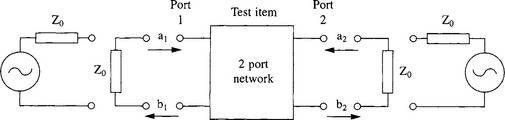
s-parameters relate the values of the inputs a1 and a2, at the ports 1 and 2, respectively of the device or circuit and the outputs b1 and b2 at those same ports.
With Generator connected to port 1 and port 2 perfectly matched (a2 = 0)
Input-Reflection Coefficient S11 = ![]()
Looking into port 1 when port 2 is perfectly matched.
Forward-Transmission Coefficient S21 = ![]()
Voltage transmission coefficient from port 1 to port 2 when port 2 is perfectly matched.
With Generator connected to port 2 and port 1 perfectly matched (a1 = 0)
Reverse-Transmission Coefficient S12 = ![]()
Voltage transmission coefficient from port 2 to port 1 when port 1 is perfectly matched.
The relations between the inputs and outputs and the scattering parameters are given below.
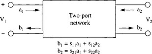
Thus the signal b1 coming out of port 1 is s11 × a1 - the sum of the reflected portion of the input a1 times the input reflection coefficient s11 - plus s12 × a2, the portion of the signal a2 input at port 2 which is transmitted through the device to port 1.
Note that the Smith Chart covers all possible combinations of a reactive component and a (positive) resistive component. Any point outside the Smith Chart represents an impedance having a negative resistive component. This corresponds to the real part of s11 or s22 being greater than unity, i.e. the port reflects more power than is input to it. If the port is terminated in the characteristic impedance, the extra power is absorbed by that termination and the system is stable. However, if the termination itself exhibits an appreciable degree of reflection, the re-reflected power entering the port again will be reflected yet again increased further in magnitude, and so on, resulting in oscillation.
More explicitly, if s11 × Ã1 is greater than unity (where Ã1 is the reflection coefficient of the source), then the system is unstable (and similarly for s22 × Ã2) and the output exceeds the input. (The extra energy comes ultimately, of course, from the device’s power supply.) Even if neither of these conditions applies, a 2-port may oscillate due to the forward gain being too large relative to the internal reverse feedback. In particular, instability will result if Ã1 s12Ã2 s21 exceeds unity. This underlines the advantages of s-parameter measurements, compared with attempting to measure h-, y- or z-parameters.
The discussion has been, so far, in connection with a 2-port device or system, such as an amplifier, but s-parameters may be defined for an n-port, where n is any positive whole number. Where n is unity, we have a 1-port, an example being a Gunn diode. This device exhibits an incremental or ‘slope’ resistance which is negative over a part of its characteristic. In use, it is connected in series with a larger positive resistance and an inductance. The result is that the circuit’s d.c. operating point is stabilised in the centre of the negative slope region of the device’s characteristic, but at high frequencies it exhibits a reflection coefficient of greater than unity. If connected to an external circuit through a transmission line, such that s11 × Ã1 is greater than unity at a frequency where the round trip delay is 360° or a multiple thereof, then oscillation results and the device can be used as a transmitter. On the other hand, if the Gunn diode be connected to a circulator (see Chapter 5), then it can be used as an amplifier.