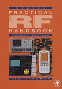
Elliptic filters
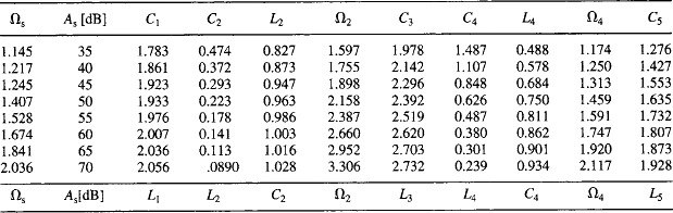
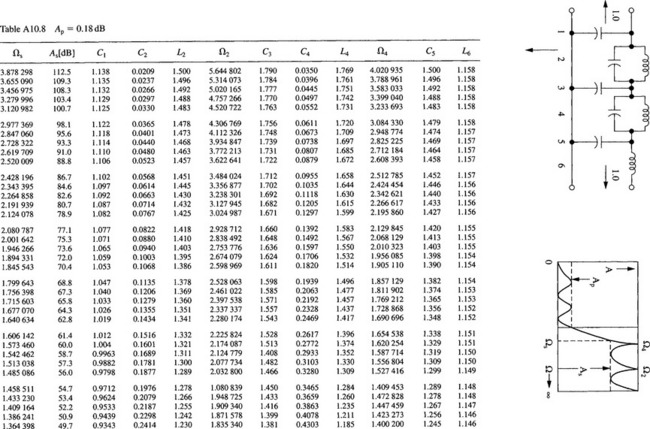
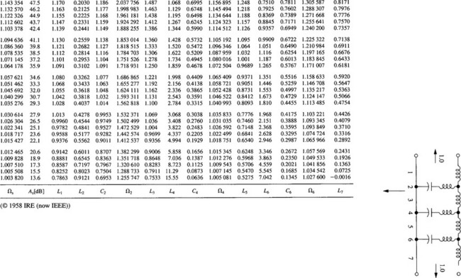
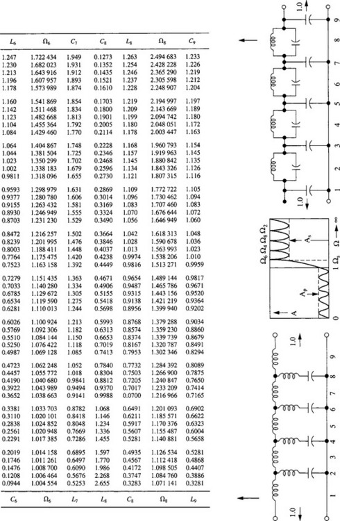
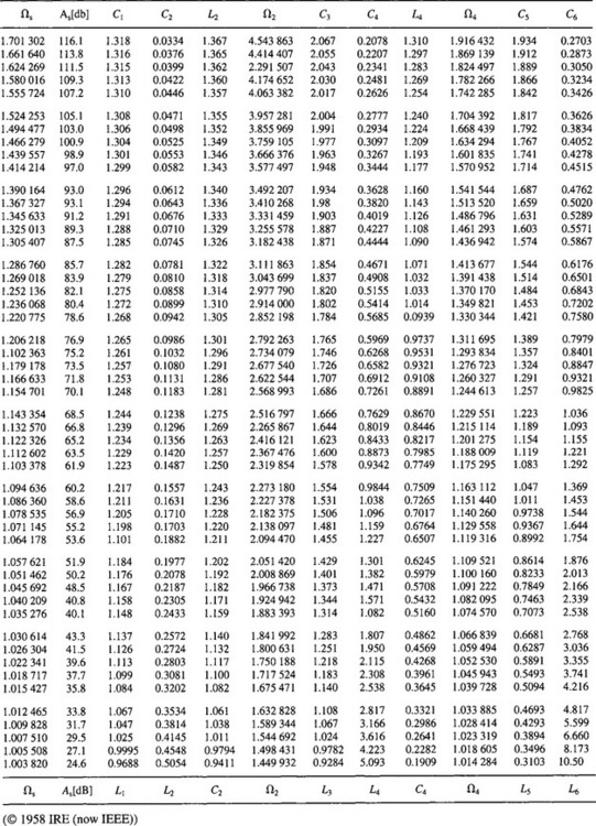
The following small subset of tables with their schematics are reprinted with permission from ‘On the Design of Filters by Synthesis’ by R. Saal and E. Ulbricht, IRE Transactions on Circuit Theory, December 1958, pp. 284-328. ((c) 1958 IRE (now IEEE)). The tables are normalized to f = 1 rad/s = 1/(2p) Hz, Z0 = 1 O,L in henrys, C in farads.
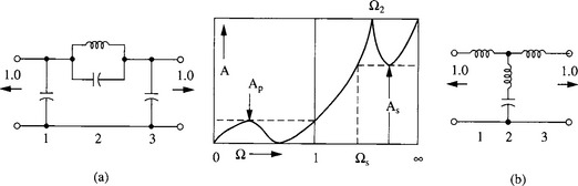
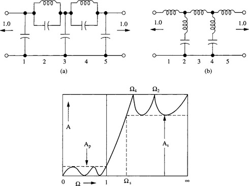
(Note: In using the following tables with the schematics, for example, for schematic (a) below corresponds with the top line of column headings of Tables A10.1–3. Similarly, schematic (b) corresponds with the bottom line of column headings of the tables.)

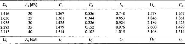
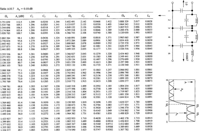
The original gives designs for filters up to the eleventh order. Designs are presented here for third and fifth order filters with 1 dB, 0.5 dB and 0.1 dB pass-band ripples, and for sixth, seventh and ninth order 0.18 dB ripple filters. For the 6-pole case, two designs are given. One is the basic 6-pole version designed to work from a normalized source impedance of unity into a normalized load impedance of 0.667 (or 1.5 for the T section design). This results in a 0.18 dB insertion loss at dc, due to the 1.5:1 VSWR. The other is a version designed to work between normalized impedances of unity at both ends and consequently has a zero pass-band loss at dc similar to that of a 5-pole filter. The first version offers a slightly faster cut-off in the stop band and is therefore to be preferred, provided that the different terminating impedances can be conveniently accommodated.