
Muting relays
What could be simpler than switching a relay on and off? This depends on how closely you want to control it. Any design problem, when looked at the right way, can be made more challenging. It is usually possible to identify a parameter that can be focused on and made the subject of some creative improvement. So it is here, where the speed of relay switch-off, and hence its ability to mute turn-off transients, is examined into in depth. This article gives amongst other advice, details on how to make relays operate faster than at first appears to be possible.
Since this article was published, further experience leads me to sound a note of warning about trying to be too quick in sensing the disappearance of the mains supply. Doubtful electrical appliances (and I am thinking of a particular veteran refrigerator here, with a vicious motor start-up transient) combined with antique mains wiring can put short-duration dips in the supply that trigger the AC-loss circuit, when in fact the hold-up time of the power supply in the equipment with the relay is perfectly capable of keeping the show going. If you run into trouble with this, increasing the value of Cl (Figure 3) should fix things.
Most power amplifiers incorporate an output relay that not only provides muting to prevent transients reaching the loudspeakers, but also protection against destructive DC faults.
Loudspeakers are expensive, and no amplifier should ever be connected to one without proper DC-offset protection. This applies with particular force to experimental amplifiers.
Sensible preamplifiers – i.e. those with AC-coupled outputs – do not require DC protection, but the muting of thumps is no less important. Electronic switching at preamp outputs is feasible, but still presents technical challenges if high standards of linearity are to be combined with a reasonably low output impedance.
Electronic output switching is impracticable at power amplifier signal levels; however, if the amplifier is powered by a switch-mode supply, then turning it off is an option if positive and negative rails can be relied upon to collapse quickly and symmetrically.
Protection circuit operation
Basic functions of a power-on thump elimination and DC protection circuit are as follows:
• Delay relay pull-in until amplifier turn-on transients are over.
• Drop out relay as fast as possible when AC power is removed.
• Drop out relay as fast as possible when DC fault occurs.
• Drop out relay on excess temperature, etc. Speed non-critical.
Figure 1 is a block-diagram of a system to perform these functions. Since this is in part a protection system, simplicity and bullet-proof reliability are essential.

The main dynamic parameters of a relay are the pull-in and drop-out time. For this kind of application, the pull-in time is more or less irrelevant, as it is milliseconds compared with the seconds of the turn-on delay.
Relay contacts bounce when they close, but the duration of pull-in contact bounce is not important for this application.
All the relays I examined showed clean contact-breaking on drop-out, and this is essential for fast muting. Table 1a gives details of three poweramp relays and the Fujitsu relay used in the Precision Preamp ’96 article.1
Table 1a
Relay specifications as presented by their manufacturers
| P&B | Oko | Schrack | Fujitsu | |
| Nominal voltage | 24 V | 18 V | 12 V | 12 V |
| Must-operate voltage | 18 V | 8.4 V | ||
| Drop-out voltage | 2.4 V | 1.2 V | ||
| Coil resistance | 660 Ω | 320 Ω | ||
| Coil inductance | 0.55 H | |||
| Pull-in time maximum | 15 ms | 5 ms | ||
| Pull-in time typical | 9 ms | |||
| Drop-out time maximum | 10 ms | 3 ms | ||
| Drop-out time typical | 7 ms |
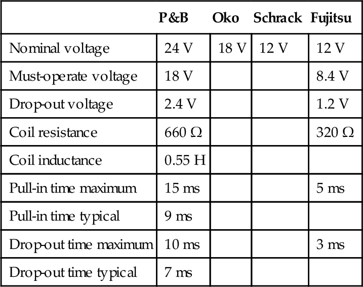
The specifications for the P&B relay are very conservative. The example measured pulled-in at 72% of the must-operate voltage, and dropped out at 350% of the must-drop-out voltage. Likewise the real operating times are much less than those specified.
The critical parameter for audio muting is the drop-out time, for this puts a limit on the speed with which turn-off transients can be suppressed. It seems at first that the drop-out time must be solely a function of the relay design, depending on the force in the bent contact spring and the inertia of the moving parts. This is partly true, as mechanical factors set a minimum time, but that time is greatly extended by the normal relay-driving circuits.
Table 1b
Measured relay specifications
| P&B | Oko | Schrack | Fujitsu | |
| Operate voltage | 13 V | 13 V | 7 V | 6 V |
| Drop-out voltage | 8.5 V | 6.5 V | 2.5 V | 2 V |
| Pull-in time | 14 ms | 10 ms | 10 ms | 2.7 ms |
| Drop-out time | 1.0 ms | 1.3 ms | 2.4 ms | 1.2 ms |
| Diode drop-out time | 5.4 ms | 6.9 ms | 11 ms | 4.2 ms |
| 27 V-clamp drop-out time | 1.8 ms | 2.4 ms | 2.7 ms | 1.3 ms |

* P&B is Potter and Brumfield.
Relay-on timing
The delay required at amplifier turn-on depends on the amplifier characteristics.
If there are long time-constants, and voltages that take a while to settle, then the muting period will have to be extended to prevent clicks and thumps. Five seconds is probably the upper limit before the delay gets irritating; one second is long enough for a silent start-up with most conventional amplifiers.
This delay function can be performed in many ways, but there are a few points to consider. The tolerance on the length of the turn-on delay is not critical, and an RC time-constant is quite adequate to define it.
It is convenient – and significantly cheaper – to run the relay control circuitry directly from the main HT rails rather than creating regulated sub-rails or extra windings on the mains transformer. The emphasis is therefore on discrete transistor circuitry.
Figure 2 shows the relay control system I used in the Precision Preamplifier ’96. Note that there was an error in the original diagram that is corrected here.
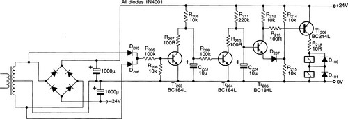
Capacitor C224 charges through R211 until D207 is forward-biased and Tr205 turns on. This turns on Tr206 and energises the relay; the extra current-gain of Tr206 enables the timing circuitry to run at low power. The on-timing delay here is 2 s.
A series dropper resistor for the relay is usually required; here it is R218. The highest voltage relay-coil available is usually 48 V, though 24 V is more common, and power amplifier rails are often much higher than this.
This reverse diodes across the relay coils prevent Tr206 being damaged by the inductive spike created when the coil is suddenly de-energised. For relays of the size used in power amplifiers, signal diodes cannot cope with the stored energy and the 1 N4001 type should be used.
Off timing criteria
The relay drop-out must be as fast as possible. If a relay is powered directly from the supply rails, then it will drop out eventually as the rails collapse, but this will be far too slow to catch turn-off noises.
The drop-out voltage may well be less than a third of the pull-in voltage, and this slows things down even more. A specific fast off circuit is required, and there are several ways to achieve this.
Mechanical detection
This is a mains switch that closes or opens a control circuit before the mains power contacts are opened. It could give perfect relay operation, but I am not aware that any such mains switch has ever been produced.
Detecting the loss of DC supply
This technique involves a subsidiary supply rail with a small reservoir capacitor. When the mains is switched off, the capacitor discharges quickly and either removes the relay power directly, or resets the turn-on delay timer. The latter is usually easier to implement.
This method is inherently slow, because the relay-off threshold must be below the ripple troughs. Therefore in the worst case, an entire half-cycle of mains must pass before the capacitor becomes fully discharged, so the delay may be 10 ms.
In practice there are component tolerances to be allowed for, and the threshold must be set low enough to prevent spurious operation if the mains voltage is below normal. It is usually prudent to ensure circuitry works with mains down to at least − 20%. This extends the minimum delay to about 16 ms. The reservoir capacitor will have a large ripple voltage across it, and its ripple-current rating must be carefully observed.
Detection of loss of AC
Detecting the loss of AC supply, as opposed to the rectified DC, is potentially quicker as there is no reservoir capacitor to discharge before the circuit operates. An AC waveform is effectively appearing and disappearing every half-cycle, so the circuit must distinguish between the zero-crossings that occur every 10 ms, and genuine loss of power.
AC loss detection
The most straightforward method of AC-loss detection exploits the fact that properly-defined zero-crossings are very brief; all that is required is a timer that will not complete and drop out the relay until a period greater than the width of the zero-crossing has expired. This delay can readily be reduced to less than 1 ms.
Referring to Figure 2, Tr203 is normally held firmly on by the incoming AC, via D205 on positive half-cycles and D206 on negative ones, and thus keeps C223 fully discharged.
At the zero-crossings, Tr203 has no base drive and turns off, allowing C223 to begin charging through R208. If the absence of base drive persists beyond the preset period, which means the AC has been interrupted, then C223 charges until Tr204 turns on and rapidly discharges the main timing capacitor C210 through R207, dropping out the relay.
When a relay is driven by a transistor, it is standard to put a reversed diode across the coil. Without it, abrupt turn-off of current causes the coil voltage to reverse, driving the collector more negative. For the relays here, the worst spike measured was − 120 V, which is enough to destructively exceed the Vceo of most transistors.
This apparently innocent, and indeed laudable practice of diode protection conceals a lurking snag; drop-out time is hugely increased by the reversed diode. It is roughly five times longer, which is very unwelcome in this particular application. This is because the diode gives a path for current to circulate while the magnetic field decays.
This is a good point to stop and consider exactly what we are trying to do: the aim is not to totally suppress the back-EMF but rather to protect the transistor.
If the back-EMF is clamped to about − 27 V by a suitable Zener diode in series with the reverse diode, the circulating current stops much sooner, and the drop-out is almost as fast as for the non-suppressed relay.
In general, drop-out is speeded up by a factor of about four on moving from conventional protection to Zener clamping. For the relays examined here, a 500 mW Zener appeared to be adequate.
Preamp enhancement
The preamp relay controller can be improved upon; it works well under most circumstances, but it could be faster. Testing showed that the delay between loss of AC and the relay power being removed could be as long as 17 ms, depending slightly on the phase of the mains when it was cut. The relay drop-out time was 5 ms giving a total of 22 ms before the preamp output is muted.
The following circuit improvements were made to speed up relay drop out.
The on-timing reference divider R214, 215 is replaced with a 15 V Zener diode. This sharpens up the relay pull-in, making a more ‘precise’ click. It also prevents the voltage on C224 rising beyond that required to turn on Tr205; discharging it when the time comes is therefore quicker.
Base drive to Tr203 is increased by reducing R205 to 22 kΩ. This defines the zero-crossing as twice as narrow, allowing the time-constant R208–C223 which bridges this period to be made shorter. Capacitor C224 therefore starts discharging sooner after AC is lost.
Impedance of the zero-crossing time-constant R208–C223 is increased by changing the values from 10 kΩ–10 μF to 100 kΩ–470 nF. This simultaneously reduces the time-constant mentioned in the previous paragraph. It is now possible to use a non-electrolytic timing capacitor, which reduces tolerances and makes the circuit more designable.
Base drive to Tr204 is increased to speed up the discharge of C224 by reducing R205 from 100 kΩ to 100 Ω.
Finally, a 27 V Zener clamp is applied to each relay, as described above.
After these improvements, the electronic delay was reduced from 17 to 5.4 ms; the total delay including contacts opening now was 9.5 ms worst case.
After adding Zener clamping to the relays this fell to 6.3 ms worst-case, the average being 4.5 ms; the improved circuit is four times faster.
These component changes can be simply retro-fitted to existing Preamp 96 circuit boards using Table 2.
Other relay functions
The extra protective functions of a power amp relay require OR-ing together several error signals for DC offset, temperature shutdown, etc.
If a DC fault occurs in a power amplifier, this typically means that the output slams hard to one of the rails and stays there. Assuming the loudspeaker does not suffer instantaneous mechanical damage, it will overheat after a relatively short period as the DC flows through it.
DC offset protection cannot prevent a loudspeaker hitting its mechanical limits, but it will stop it catching fire if the relay opens promptly. Once more, time is of the essence.
Usually, DC offset is detected by passing the amplifier output through an RC time-constant long enough to remove all audio, followed by a DC-detect circuit that responds to offsets of either polarity.
To allow a safety margin against false triggering on bass signals, I decided that the RC filter must accept full output at 2 Hz without the detector acting. For example, if it triggers at ± 2 V, then for supply rails of ± 55 V there must be 29 dB of attenuation at 2 Hz; with a single pole this means a − 3 db frequency about 0.07 Hz.
This sort of low-pass filtering inevitably introduces a time delay; if the output leaves 0 V and moves promptly to one of the rails, this will be 50 ms with the circuit of Figure 3.

Detecting offsets of either polarity requires a little thought. Figure 4 shows a common circuit; a positive voltage turns on Tr8 by forward biasing its base, while a negative voltage turns on Tr7 by pulling down the emitter. The presence of DC is indicated by the collector voltage falling.
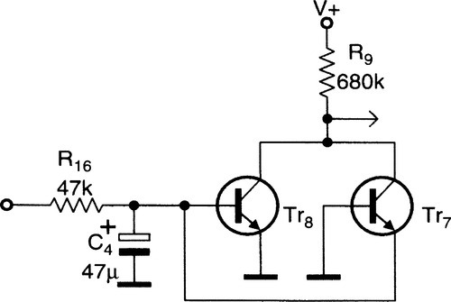
This solution is simple but highly-asymmetrical, requiring either + 1.05 V or − 5.5 V to pull the collectors down to 0 V. For positive voltages the stage is common-emitter with high voltage gain, but for negative ones it works in common-base with a lower voltage gain, set by the ratio of R16 and R9. It is difficult to make this ratio large without R16 becoming too small and hence C4 inconveniently big.
If you’re unlucky – and chances are you will be – the offset will have the wrong polarity for C4, which will degrade if left reverse-biased for long periods. Two ordinary electrolytics back-to-back is the cheapest solution.
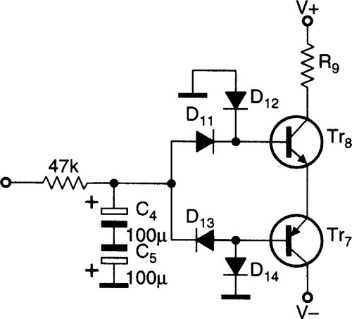
The improved DC detector in Figure 5 is fully symmetrical. Positive voltages turn on D11 and Tr8; Tr7 also conducts as its emitter is pulled up by Tr8, while its base is held low by D14. Negative voltages turn on D13 and Tr7; Tr8 conducts with its base fed by D12. The threshold is now ± 2.4 V, as for each polarity there are two diodes and two base–emitter voltages in series. The higher threshold is not a problem as the typical amplifier fault snaps the output hard to one of the rails.
One exception to this statement is HF instability. If an amplifier bursts joyfully into HF oscillation, it will almost certainly show slew-limiting as well. This is unlikely to be very symmetrical so there will be a DC shift at the output.
The magnitude of this is not very predictable, but a 2.4 V threshold will detect most cases. This should save your tweeters, though it may not save the amplifier from internal heating due to conduction overlap in the relatively slow output devices.
Figure 5 can be adapted for stereo simply by adding two more diodes, as in Figure 3. Note that a positive offset on one channel and a negative one on the other – admittedly highly unlikely – do not cancel out; a fault is still signalled.
Power amplifier relay control
Figure 3 shows a power amp relay controller, designed for ± 55 V rails and 24 V relays such as the P&B T 90 type outlined in Table 1a. The main differences are the inclusion of DC offset detection and an efficiency circuit to minimise dissipation in the relays, which are now larger than in the preamp, and require more power.
The DC-detect circuit rapidly discharges on-timing capacitor C2 through D3 when Tr8 collector goes low. An extra OR input for thermal shutdown acts via a series diode in the shutdown line.
The circuit now uses MPSA42/MPSA92 transistors to withstand the higher supply voltages; as usual higher Vceo means lower current-gain, which must be allowed for in the detailed design.
The electronic delay until coil switch-off averages 2 ms, the timing being shown in Figure 6. The AC was interrupted at centre screen, and a large positive-going off-transient can be seen just to the right. This is due to the leakage inductance of a large transformer.
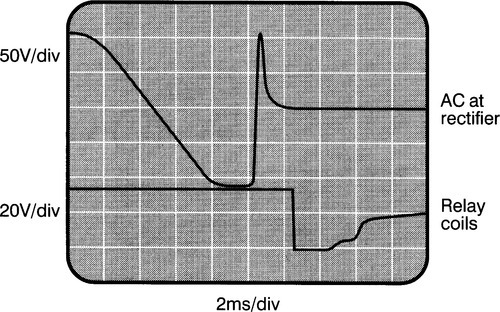
The loss of AC cannot be detected until this transient decays to zero, so the delay is slightly extended. This was not a problem with the preamp version as it uses a small toroid with much less leakage inductance.
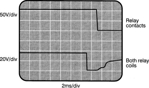
Figure 7 shows the relay coil voltage. At switch off it goes straight down through zero until clamped by the two Zeners at around − 50 V. This puts 105 V on Tr4 collector, which is no problem as it is rated at 300 V Vceo. The relay contacts open just as clamping ceases and the coil voltage returns slowly to zero. Drop-out time is 1.8 ms, giving a total delay of 3.8 ms.
Efficiency circuit
All relays have a pull-in voltage that is greatly in excess of that required to keep them closed. It is therefore possible to save considerable power by applying full voltage only briefly, and then reducing it to a level which is still safely above the maximum drop-out voltage.
From Table 1a there is plenty of scope for this. By comparing the specified and measured performance, you will see that the P&B relay can be trusted to pull in at 18 V and not drop out above 8.5 V.
The initial pulse is provided by Tr5 and R13. At switch-on, Tr4 is off and Tr5 does nothing. After the on-timing delay Tr4 conducts, Tr5’s emitter is pulled up, and its base receives a pulse of current via R14 and C3. Resistor R13 is shorted by Tr5 and the relays get a voltage reduced only by R12; see Figure 8.

After 40 ms, C3 is fully charged and Tr5 turns off; this is at least four times longer than the minimum pulse to pull-in the T90 relay, but may be adjusted to suit other types by altering C3. Diode D10 protects Tr5 at switch-off.
In Figure 3, the initial voltage is 22 V per relay and the holding voltage 12 V, giving an initial power consumption of 1.85 W, falling to 960 mW long-term. The total power saving is just under a watt.
Running relays at a reduced holding voltage not only avoids the inelegance of consuming power for no good reason, but also speeds dropout time by reducing the magnetic energy stored. It could be argued that such a power saving is negligible. In a big Class-A amplifier it might be, but it makes sense in modest Class-B amplifiers idling for much of the time – which is of course almost all of them.