Using Hardware Serial
Every Arduino has at least one hardware serial port. We have already used this port to send our compiled sketches to the Arduino board each time we upload our code. The single hardware serial port on the Arduino Uno is connected to both the USB to Serial convertor chip on the interface board, as well as digital pins 0 and 1. This allows us to either communicate from our computer's USB port to the Arduino board or for the Arduino board to communicate with other devices.
Serial communication is a process of sending and receiving bytes of data in a sequential manner. Two of the microcontroller's pins are needed for this communication: pin 0 is the receive pin marked RX and pin 1 is the transmit pin marked TX. These pins are also connected to two of those blinking lights that go mad each time we upload a sketch. When connecting two serial devices to each other, it is necessary to cross-connect the TX pin from Device 1 to the RX pin of Device 2 and vice versa. This also means that anytime we are using the hardware serial communications to talk to things, we cannot have anything else connected to pins 0 and 1. Likewise, if an external device is connected to the Arduino RX or TX pins, then we will not be able to upload a new sketch until those pins have been disconnected.
The serial communications protocol sends data in 8-bit chunks, or 1-byte at a time. In the hardware implementation, the serial bus has an available buffer of 128 bytes, meaning that data up to this size will not be lost if the Arduino is busy doing something else and will be available the next time the data is read. Owing to the usefulness of serial for displaying information in terminal windows and other display devices, there are two ways to send this data: as a numerical value and as a character value. As a byte data type, we can send numerical values between 0 and 255 in each transmitted packet.
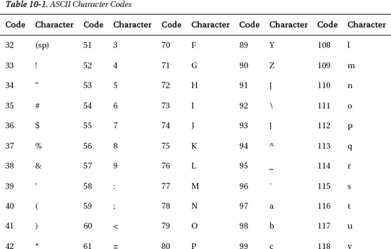
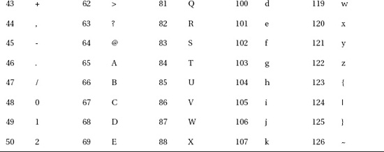
Instead of using simple numerical values, we can use the char data type to send a character value that corresponds to a standard protocol called ASCII, short for American Standard Code for Information and Interchange. ASCII is a method of coding characters with a value from 0 to 255. For example, the character 'a' translates to the value 97. We will revisit this shortly but for now, Table 10-1 provides a chart of the ASCII character codes and the corresponding characters.
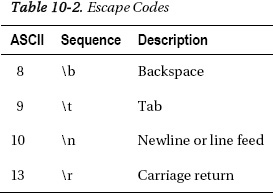
The ASCII codes also contain something called escape codes. These characters have been around for a while and control things like character returns, tabs, and line feeds or newlines. Later in our example code, we use the sequence '/n', which is one of the control characters, a non-printable character that controls the behavior of a device, to signal when a line has been entered. Table 10-2 provides some of the common escape codes.
Finally, how fast we send our packets of information is called the data rate or sometimes the baud rate. This is a measure of how many pulses are being sent or received in one second, also known as bits per second (bps). A sort of de facto standard baud rate for the Arduino is 9600 bps although the microcontroller is capable of communications at a range of speeds up to 115,200 bps, as needed by whatever specific devices that the Arduino is connected to. Both the sending and receiving device need to be set to the same data rate to ensure that both devices are speaking at the same speed.
With the boring basics for using serial communications out of the way, let's turn our attention to the next project and some of the Serial functions available to us.