
![]()
Using Layer Diagrams
How often have we seen a well-thought-out design degrade because we lose control over the way our code evolves? One common reason for that is badly managed dependencies. In Chapter 12 we looked at how Architecture Explorer and the dependency diagram can be used to visualize code dependencies and to help us detect problem areas in our codebase. It would be better, though, if instead of having a tool to help us find issues in our code, we had one that would help us prevent the problems in the first place.
One such tool is the layer diagram. Part of the architecture tools in Visual Studio Ultimate, the layer diagram is used to model the layers in a solution. Once the layers are defined, we can define the dependency structure between the layers and map code to the corresponding layer. With this information in place, the model can be used not only as documentation but also to enforce that modules in the application do not take dependencies outside what is defined in the model.
The architecture archetype pattern we used for our solution unfortunately has a tendency to become a white-board product and not necessarily one followed by developers. Implementing the pattern as a layer diagram will help us maintain dependencies over time and prevent the code from becoming hard to maintain.
Patterns
Before we look at how layer diagrams work, we need a bit of background. Software patterns are commonly used in software development; one kind is the structural pattern for describing a software architecture archetype. We use these patterns to group components into logical layers in order to create a good separation of concerns in the application. Examples of architecture patterns are client-server and service-oriented architecture. Figure 13-1 shows an example of a service-oriented architecture.

Figure 13-1. Model for a service-oriented architecture
A good start for more information about patterns for Microsoft architecture is the Microsoft Application Architecture Guide, 2nd edition (http://msdn.microsoft.com/en-us/library/ff650706.aspx). The guide covers architecture and design principles as well a good walkthrough of common application archetypes.
Using Layer Diagrams
Ideally, we use the layer diagrams throughout the development process. We begin by creating the diagram as part of the architecture and design phase. When we start development, we add components to the corresponding layer, and from then on we validate the code against the model to ensure we do not break the layering model. In the following sections we look at how to create a diagram, add components to it, and validate the model.
Creating a Layer Diagram
To create a layer diagram, we need to have a modeling project in our solution, and then we can add new layer diagrams to it. The modeling project is often a part of the main solution used for development, and keeping the layer diagrams in the same solution makes it easier to keep the model in sync with the code. But we can have the modeling project in a stand-alone solution and add references to project components as binary references.
The layer diagram is very straightforward to work with. Just add the layers from the architecture to the model. The layers can be nested, for instance, to have a presentation layer containing sublayers UI Components and Presentation Logic Components. We can also use colors to further improve the readability of the model. Figure 13-2 shows how to set the properties for a layer in the diagram.
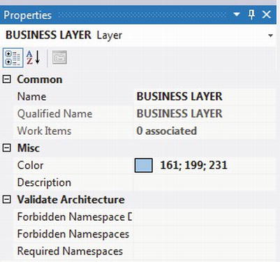
Figure 13-2. Layer properties
After creating the layer structure, we can define the relationships in the model. The core idea with layer diagrams is to define which layers depend on which others. For example, if we are building a system using a Domain Driven Design1, a domain model component would typically be used by business services and perhaps UI components. We can make this explicit by drawing a dependency between the layers. Table 13-1 lists the elements available in the layer diagram.
Table 13-1. Elements available in the layer diagram
| Element Name | Purpose |
|---|---|
| Layer | Defines a layer in the diagram. |
| Dependency | Defines a one-way dependency in the diagram. |
| Bidirectional Dependency | Defines a two-way dependency in the diagram. |
| Comment | Annotation to the model. |
| Comment Link | Associates a comment with a model element. |
Mapping Code to Layers
When the layer structure is in place, we can start adding code to the layers. This is typically something that we continue to do as the project goes on. When new components or namespaces are added, we map them into the correct layer. A common problem is that the architecture diagrams become stale. To prevent this, we should add new components to the solution through the models first. This way we get the documentation up front, and in the case of layer diagrams, we get the benefit of dependency validation as a bonus. If this presents a problem, architecture diagrams should probably not be used in the project.
Next, after the layers are in place, we should define the dependencies between them. We can add dependencies manually by using the Dependency or Bidirectional Dependency association.
Should we come from a situation in which we are creating layer diagrams from an existing codebase, we can also let the tool generate the dependencies by using the Generate Dependencies command from the context menu in the diagram. Generate dependencies will inspect the associated components and create dependencies between the layers accordingly.
To add a component, we use Solution Explorer and drag elements (assemblies, classes, methods, and so on) to the corresponding layer. Figure 13-3 shows a complete example of a layer diagram with associated components.
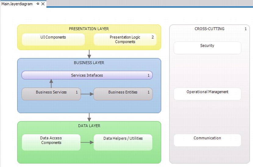
Figure 13-3. A complete layer diagram
Viewing Dependencies using Layer Explorer
The dependencies in the model are shown as numbers in each layer. Often you would want to see what is actually mapped to the layer. To do this, select the layer and open Layer Explorer, as seen in Figure 13-4.
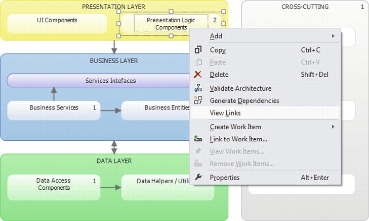
Figure 13-4. View links
Layer Explorer will display all the associated code elements, as shown in Figure 13-5, where we can view and modify the elements.
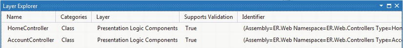
Figure 13-5. Layer Explorer
Sharing Models
The layer diagrams can be edited only with the Ultimate version of Visual Studio, but a user of Visual Studio Premium can view them. You also can export images from diagrams to share with non-Visual Studio users—just open the model to export, copy the image using copy and paste, and paste it into another application as an image file.
Layer Validation
When we have the layer model defined, we can use it to validate the implementation. The validation helps us find discrepancies between the model and our code and tells us about differences between the design and the code, which helps us find code that is not organized as designed. The validation also helps us find unwanted dependencies—for example, calls to data-access code directly from the UI, where the design mandates always to use a service layer to abstract the data layer from the UI code.
We can also use the layer diagram to test a change in design, by remodeling to the new pattern we can map the existing code and validate which dependencies would be affected.
There are several ways to perform the validation, both manually and integrated, as part of the build process. Let’s look at how to run the validation and how to analyze the results.
![]() Note By default, the layer diagram understands only managed code. If you have an application build in C/C++, you can install the Visual Studio 2010 Visualization and Modeling Feature Pack2 which will enable support for these languages as well.
Note By default, the layer diagram understands only managed code. If you have an application build in C/C++, you can install the Visual Studio 2010 Visualization and Modeling Feature Pack2 which will enable support for these languages as well.
Manually Validate Layer
We can start a validation manually from the diagram surface. Running the validation will show the result of the validation in the build output window in Visual Studio, as seen in Figure 13-6.
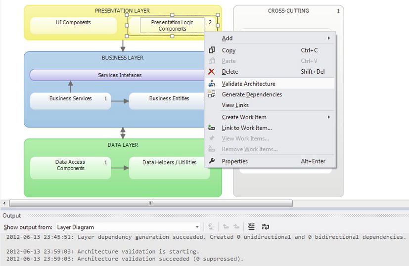
Figure 13-6. Running layer validation manually
If the code and the model don’t match, we will get errors in the output window (Figure 13-7). You can analyze the errors just as with any other build error in Visual Studio.
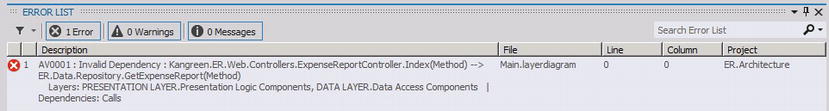
Figure 13-7. Layer validation error in Visual Studio
The error in this case is caused by ExpenseReportController makes a call directly to the Repository.GetExpenseReport, a call from the presentation to the data layer, which is not allowed in the model. To fix this, we could refactor the code so the presentation logic calls a business service that in turn would call the repository method.
Validate in local build
Once the layer model has been added to the solution, it makes sense to run the validation as often as possible. Validating often ensures that a change in code that breaks the design is identified immediately and can be corrected by the developer even before committing the new code to the repository. To make the validation run as part of the build, we need to set the following msbuild property in the modeling project:
<ValidateArchitecture > true</ValidateArchitecture>
![]() Note Running layer validation as part of a build will slow down the build process. If you want to automate layer validation, we recommend that you integrate the validation as part of your automated build process.
Note Running layer validation as part of a build will slow down the build process. If you want to automate layer validation, we recommend that you integrate the validation as part of your automated build process.
We can also set this property in the model project’s property window, as shown in Figure 13-8.
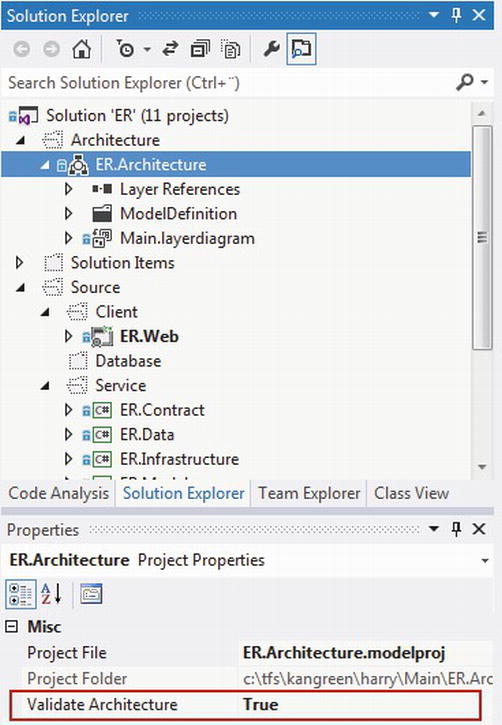
Figure 13-8. Layer Explorer
When compiling the project as a developer, we will also get the layer validation as part of the build output (Figure 13-9).
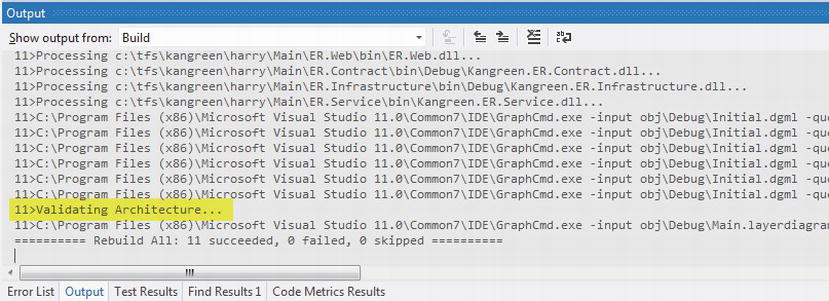
Figure 13-9. Validating the model as part of a local build
Validate in TFS Build
If we are using TFS Build to do server-side builds, we should of course validate the layer model as well. If we check in a model project, which is defined for local build, TFS Build will pick this up automatically and build using the same settings. If we want to validate the layer model as part of TFS Build, we must provide the /p:ValidateArchitecture = true MSBuild parameter ,as shown in Figure 13-10.
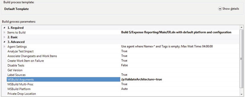
Figure 13-10. Running layer validation as oart of a TFS Build
Creating an Architecture Template
If we want to reuse the architecture and design work, we can export projects into a new Visual Studio Template. To do this, open the modeling project in Visual Studio and use the Export Template feature under the File menu. This will create a .zip-file that we can distribute and install to use when creating new project.
![]() Note For Visual Studio 2010, Export Template Wizard will export and package the template as a setup file for easy distribution (http://visualstudiogallery.msdn.microsoft.com/57320b20-34a2-42e4-b97e-e615c71aca24).
Note For Visual Studio 2010, Export Template Wizard will export and package the template as a setup file for easy distribution (http://visualstudiogallery.msdn.microsoft.com/57320b20-34a2-42e4-b97e-e615c71aca24).
Summary
In this chapter, we have looked at how the layer diagram can be used to describe the interation rules for components in different layers in a system and how the model can be used to enforce these rules over the lifetime of the product.
This concludes the architecture section of the book. We have looked at the new Visual Studio tools for requirement elicitation using storyboarding and feedback. We have looked at using UML for use-case modeling as well as architecture modeling. Last, we have explored the architecture exploration tools and the layer diagram—tools that can help us understand the structure of an existing application as well as help us make sure the application continues to be maintainable over time.
Next we will look at development practices and how we can apply ALM to the build phase of the development project.