
CONTENTS
11.3 Manufacturing of Cable with Extruded Insulations
11.3.1 Insulating and Jacketing Compounds
11.4 Extrusion Line Configurations
11.4.3 “Single Pass” Extrusion
11.4.4 “True Triple” Extrusion
11.5.5 Drying and Impregnating
11.5.6 Conditioning the Impregnating Fluid
11.5.7 Control of Impregnation
11.5.8 Control of the Cooling Cycle
11.6.1 Electrical Tests for 100% Inspection of Low Voltage Cables
11.6.1.1 Alternating Current Spark Test
11.6.1.2 Direct Current Spark Test
11.6.1.3 Alternating Current Water Tank Test
11.6.1.4 Direct Current Water Tank Test
11.6.1.5 Insulation Resistance Test
11.6.2 Electrical Testing of Medium Voltage Cables
11.6.2.1 Alternating Current Voltage Withstand Test
11.6.2.2 Partial Discharge Test
Insulated electric power cable manufacturing involves a broad range of complexity depending on the cable design to be produced [1,2]. Different cable plants may be capable of a limited or broad range of designs. Those capable of a broad range may limit operations to only a few steps in the manufacturing process.
Despite this large variability in plants, the steps in the manufacturing process remain basically the same, whether done in one facility or a number of facilities. Conductor manufacturing is common to all cables with metallic conductors. The manufacture of extruded dielectric power cables and laminar dielectric power cables follows.
In Chapter 3 (Conductors), it was pointed out that for efficient distribution of electric power, the conductors must be produced from a high conductivity material. It was also shown that copper and aluminum offer the best available combinations of conductivity, workability, strength, and cost to become the most popular power cable conductor materials. From the conductor-manufacturing standpoint (we will not attempt to include mining, refining, and fabricating stages), we will begin at the point where copper and aluminum are received as large coils of round rod. The diameter of aluminum rod for producing conductors is commonly 3/8 inch in diameter (0.375 inches, 9.53 mm) while 5/16 inch (7.94 mm) diameter is common for copper rod. For larger solid conductors; [i.e., #1/0 AWG or larger (0.325 inches diameter, 8.26 mm)], it is common to begin with a larger diameter rod. The larger diameter (often 0.500 inches, 12.7 mm) allows for enough diameter draw-down to remove surface imperfections in the rod, as received, to make a conductor surface without residual surface imperfections.
In wire drawing, the copper or aluminum rod is drawn through a series of successively smaller dies to reduce the rod to a wire of the desired diameter. The quality of the wire surface depends on sufficient drawing and reduction to eliminate surface defects. Thus, there is the need to utilize a rod or intermediate wire having a diameter somewhat larger than the solid wire to be produced. If fine wire is desired, it is common to utilize a coarse wire-drawing machine followed by a fine wire-drawing machine. The wires are taken up on spools for later stranding operations or on reels for use as a solid conductor.
Drawing copper or aluminum wires increases the temper of the metal. That is, a rod of a “softer” temper is “hardened” as the wire is drawn down to the required diameter.
Except for the use of full hard temper aluminum stranded conductors for electric utility outside plant secondary and primary cables, it is generally desirable to use a softer temper. To produce a softer temper, the wire is exposed to elevated temperatures well in advance of emergency operating temperatures of the cable. For many years, this has been accomplished in a large oven. Exposure time using this method is a matter of hours.
It is possible to partially anneal wires “on the fly.” This is generally done on a wire before it is used in a stranding operation. The method is not generally suitable for full annealing to a soft temper or to conductors after they have been stranded.
Another method of arriving at wires of the desired temper is to begin with rods of a softer temper and using the work hardening associated with the wire drawing to arrive at the desired temper.
The simplest conductor is a solid rod/wire. As the cross-sectional area of the conductor increases, the conductor becomes increasingly stiff. Stranded conductors use a number of smaller wires, the sum of which totals the desired conductor cross-sectional area. The machines used in stranding range from those that apply successive layers of strands over a central core made up of one or a number of strands, to those producing stranded configurations resembling ropes and for very fine wires making bunches of fine strands. See Figure 11.1 for an example of a seven-wire strander in operation.
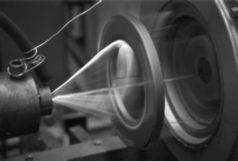
FIGURE 11.1 Conductor strander in operation.
11.3 MANUFACTURING OF CABLE WITH EXTRUDED INSULATIONS
11.3.1 INSULATING AND JACKETING COMPOUNDS
There are literally thousands of insulating and jacketing compounds used in the cable industry. Many of these compounds are commercially available from compound suppliers. They may also be custom compounded by companies that sell them as finished, “ready-to-extrude” compounds. The cost of “ready-to-extrude” compounds is high enough so there is considerable incentive for the manufacturer to mix many compounds in-house. Low voltage compounds provide special opportunities ranging from the simple addition of one or more ingredients at the extruder to the complete mixing of all the ingredients and the production of strips or pellets suitable for extrusion. The complex subject of compounding is beyond the scope of this chapter. For our purposes, we will assume compounds are complete, “ready-to-extrude.” However, it is necessary to recognize that this all-important compounding step is increasingly becoming a part of the manufacturing process.
The extrusion currently in use to produce polymeric layers comprising the cable is similar regardless of the polymer or layer being extruded.
Compound, in the form of pellets or strips, is fed into the back of a screw that rotates in a barrel. The material advances down the screw and is melted during the advance. In general, the barrel is divided into zones that are individually temperature controlled. There are some extruders where the barrel is heated at the start of the extrusion, but as the extrusion continues the mechanical shear and friction result in sufficient heat generation that barrel heating is no longer required. In fact, depending on compound and extrusion parameters, barrel cooling and even screw cooling may be required. Properly executed, the compound is all melted and forced through a die-head arrangement that deposits the melt on the core being passed through the head. This core may be a bare wire or cable in some stage of completion. Figure 11.2 shows the common features of an extruder. Figure 11.3 shows the physical arrangement of three extruders and the crosshead at a manufacturing facility.
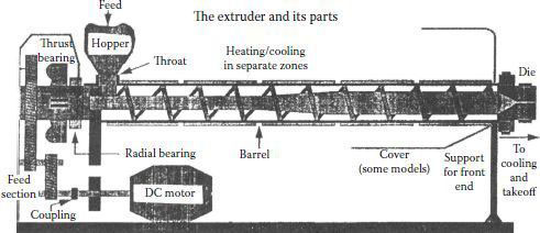
FIGURE 11.2 Extruder.
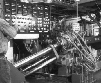
FIGURE 11.3 Crosshead and extruders.
In many cases, the compound is introduced with all of its final ingredients included. However, variations such as the addition of curing peroxides, color concentrates, or other ingredients at or near the extruder are quite commonly used.
This term is somewhat of a carryover from the rubber materials that required curing. The cross-linking process for modern thermosetting compounds, such as cross-linked polyethylene and ethylene propylene rubber (EPR), is often referred to as a curing stage. While materials such as polyethylene can be cross-linked by a radiation-induced reaction, the majority of cross-linking for power cables continues to be by the chemical means.
Taking a simple case of polyethylene, the addition of a peroxide agent such as dicumyl peroxide to the polyethylene and supplying heat energy results in a chemical reaction that cross-links the polyethylene turning it from a thermoplastic material into a thermosetting material. Peroxides are also commonly used for cross-linking EPR compounds. The heating period to effect cross-linking is commonly called curing. It is also referred to as vulcanization (a carry over from the tire industry), hence reference to the CV tube is the “continuous vulcanization” tube.
Curing tubes have three distinct configurations. The most commonly used is a curved tube that is in the shape of a catenary as shown in Figure 11.4. The first portion is the curing section and the lower portion is the cooling section. The shape is designed to prevent touch-down of the cable until the cable has cured. The weight of the cable, line speed, and length of the total tube must be considered in this design. Other forms of curing tubes may be horizontal or vertical. Horizontal tubes are used for very small cables or, for large thick insulation walled cables, in special extruders that employ very long dies. A vertical extruder has the advantage of being able to make very large cables with thick insulation walls, especially transmission cables. They run relatively slowly, but gravity does not work to deform the shape of the cable.
FIGURE 11.4 Curing section of dry cure CV line.
The heat source most commonly used in the past was steam in a tube through which the extruded cable was passed. This continues to be the most popular means for curing secondary cables. When curing relatively heavy walls such as primary cables, the upper limit on temperature that steam can practically impose makes it desirable to use other heat sources. The most popular heat source today for medium and high voltage cables is radiant heating in a nitrogen-filled tube. This is one of a number of dry curing methods. This method allows for much higher curing temperatures and therefore faster line speeds and curing. These curing tubes are divided into a number of zones each of which has its individual temperature controls. This allows for optimum temperature profiling to effect cure.
Because of the high temperature involved, care must be taken to avoid thermal damage of the polymer. More common in Europe, and gaining popularity in North America for cables up to 600 volts, is silane curing. The system is based on the technology of silicones, and “Sioplas” as originally developed is a two-part system of cross-linkable graft polymer and a master batch catalyst.
A further development, “Monosil,” introduces ingredients at the extruder and thus eliminates the grafting process. Water is the cross-linking agent in these silane systems and cure rates become very thickness-dependent. One of the advantages of moisture curing is that a thermoplastic extrusion line (no curing tube as required for peroxide curing) can be used to produce the thermosetting cable.
Thermoplastic materials, such as polyethylene or polyvinyl chloride, do not require curing. Single layers that are relatively thin, such as in 600 volt building wire, may be cooled in a water trough following extrusion. In the case of polyethylene, care must be taken to avoid too rapid a quench. This rapid cooling can result in locked-in mechanical stresses which will result in shrink-back of the material on the wire.
Heavier thermoplastic layers, such as encountered on primary cables, require gradient cooling to avoid these stresses in the polyethylene.
Following curing, thermosetting materials must also be cooled. When steam is the curing medium, water cooling is universally employed. Cross-linked polyethylene must not be rapidly quenched to avoid “shrink back” that is caused by locked-in stresses. Cooling zones are used to control the cooling process for water-cooled cables.
With the dry cure process, there is the possibility of using nitrogen as the cooling method. This is not frequently used for cables at this time. Cooling is sufficiently gradual that stresses are not locked-in.
11.4 EXTRUSION LINE CONFIGURATIONS
The simplest configuration for an extrusion line is one that can be used for low voltage thermoplastic cables having a single plastic layer over a conductor (Figure 11.5). A few examples of cables that are produced this way are:
• Line wire
• Building wire
• A jacket over other cores
A curing zone may be added just before the cooling zone if curing is needed.
Thermoplastic primary cables have been produced in a similar line configuration, but two separate extruders were used to apply the conductor shield and the insulation. Another “pass” through the third extruder after the first two layers were applied and cooled became known as “two pass.” The figures that are shown here do not imply that the curing and cooling tubes are straight. The figures represent all possible configurations.
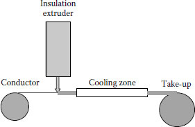
FIGURE 11.5 Single extrusion.
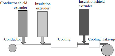
FIGURE 11.6 Triple tandem single pass extrusion.
If the product was to be cured, a curing zone had to be included. Note that the third extruder in Figure 11.6 was placed after the first cooling zone. That made it difficult if not impossible to maintain the desired strippability of thermosetting insulation shields over thermosetting insulations. Thus, it was common to utilize a thermoplastic insulation shield over thermosetting insulation.
11.4.3 “SINGLE PASS” EXTRUSION
The development of semiconducting thermosetting shield materials that would be readily strippable from thermosetting insulation even though all three layers were cured at the same time led to the development of lines where all three layers of a primary cable could be extruded over the core prior to any curing or cooling.
Figure 11.7 shows a single pass extruder where the conductor goes in at one end and the three layers are applied by three different extruders but in one complete operation.
This was the first time the “triple extrusion” term was applied. While this arrangement was preferable to all previous methods because of minimal exposure of the insulation to possible contamination or abuse, further developments were desired. Dual extrusion of the insulation and insulation shield layers would make for a smoother interface. Thus, the next improvement was single extrusion of the conductor shield and then, a few feet away, the dual extrusion of the insulation and the insulation shield. This was also called “triple extrusion”! About this time, dry curing lines were growing in popularity and many lines of this type were installed.
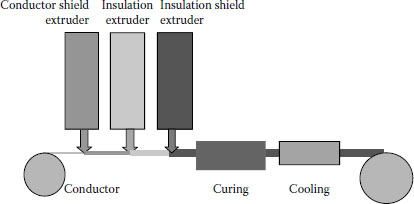
FIGURE 11.7 Single pass with three extruders.
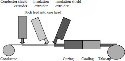
FIGURE 11.8 Single pass with one dual extruder (triple tandem).
While the extruders are essentially the same (Figure 11.7), the insulation and insulation shield extruders feed into a single head (Figure 11.8).
Unfortunately, this method continued to allow the conductor shield to be vulnerable to scraping in the next extrusion head, continued to allow build-up on the extruder die face (die drool), and exposed the conductor shield to the environment.
11.4.4 “TRUE TRIPLE” EXTRUSION
The method now used for the majority of medium voltage cables utilizes a single crosshead where all three layers are applied simultaneously. This is referred to as “true triple” extrusion (Figure 11.9).
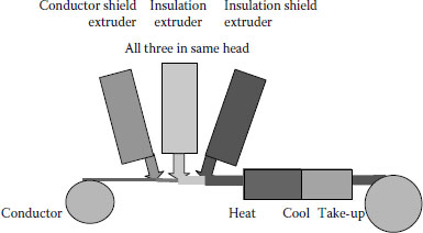
FIGURE 11.9 True triple extrusion.
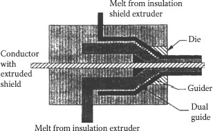
FIGURE 11.10 Dual style crosshead.
All three extruders feed into a single head for “true triple” extrusion. There are numerous lines now in service in North America, and the world in general, that make use of these triple heads.
Extrusion heads are designed to “channel” the extrudate onto the wire or cable passing through the head. Dual and triple heads channel the flow of two or three extruders in a single head. Figure 11.10 shows a cut away view of a dual crosshead and Figure 11.11 shows a triple head.
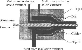
FIGURE 11.11 Triple style crosshead.
Finishing operations generally include the addition of wires, tapes, or braids (in medium-voltage cables, the addition of metallic shields) prior to jacketing.
In cases of covered overhead service cables and similar constructions, a number of single cables may be assembled as a group. This is done on cablers or twisters. The equipment has some similarity to the equipment discussed under stranding. For assemblies to be jacketed later and serve as multiconductor cables, it is common to add fillers to “round out” the assembly as well as use taping heads to apply binder and jacketing tapes in the same operation.
It has been found that up to a certain point, the mechanical strength of paper increases with its moisture content. Accordingly, prior to their use in the taping machine, pads (rolls) of paper are conditioned for a definite period in a room in which the temperature and humidity are controlled. This procedure ensures that all of the paper is in the same condition as it is being applied over the conductor and results in more uniformity in the taped insulation. When the paper is dried prior to impregnation, it shrinks uniformly. This allows for cables with sector conductors to be cabled without wrinkling.
The importance of controlled tension in the taping process is realized when one is reminded that to have an optimum of electrical strength, paper insulation must be tightly applied, free from wrinkles, and other mechanical defects that non-uniformly applied layers of tapes would have. Close, automatic control must be accomplished.
In one method, the tape from the pad passes around a pulley that is geared to a small motor armature whose direction or rotation is opposite to the direction of tape feed. As the tape feeds along, the armature is revolved opposite to the direction it would take if turning freely and against the motor field torque. The pulley, therefore, exerts a back pull on the tape at all times and with a constant value. Torque must be regulated to the tension that is required. See Figure 11.12 for an example of a paper taping machine.
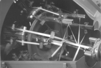
FIGURE 11.12 Paper taping machine.
A large cabling machine is used for assembling individually insulated conductors into two-, three-, or four-conductor cables. The cradles may be operated rigidly or in a planetary motion to accommodate the large diameter cabling bobbins. This reduces the bending stresses to which the paper is subjected. Facilities are provided for mounting smaller bobbins between cradles that may be used for fillers, smaller cables such as fiber optic, or tubes. Small packages of fillers may also be carried on the spindles. Guides and bushings are used for placing sector-shaped conductors in their proper position without undue strain on the insulation. Behind the assembly bushings, heads are mounted for applying paper tapes on nonshielded type cables, or in the case of shielded cables, intercalated binder tapes.
Metal binder tapes are spot-welded when a new pad of tape is inserted in a taping head. The cable is drawn through the machine by a large capstan to a take-up reel. The large diameters of the capstan and impregnating reels reduce the bending stresses in the insulation.
Paper cables have been impregnated with numerous compounds over the years. A few that have been used include:
• Type A: Unblended naphthenic-base mineral oil
• Type B: Naphthenic-base mineral oil blended with purified rosin
• Type C: Naphthenic-base mineral oil blended with a high molecular weight polymer
• Type D: Petrolatum blended with purified rosin
• Type E: Polybutene
When paper-insulated cable is impregnated with a dielectric fluid, the combination is better than either individual components alone and results in valuable characteristics:
1. High initial electrical resistivity
2. Low rate of deterioration from high temperatures
3. Low power factor
4. Very flat power factor vs. temperature curve
5. Low ionization factor
Investigation had shown that the unblended mineral oil was the most stable oil from a chemical and electrical standpoint. Natural inhibitors in the petroleum afforded high oxidation stability.
These inhibitors are complex resins occurring naturally in crude petroleum. For the most part, they are eliminated in the refining process and necessarily so because they represent impurities. If the petroleum is overrefined, all these inhibitors are removed, resulting in a clear oil of high electrical characteristics but having unstable qualities. These resins act as antioxidants by taking up oxygen themselves from the oil and thus inhibiting oxidation deterioration. In the refining process used for this oil, a good balance is obtained between electrical characteristics and high thermal stability. Most of the oil impregnated, medium voltage cables were made with Type A compound. Types B, C, and D were more viscous than Type A and were suitable for long vertical runs or slopes with Type C being the most frequently used compound.
The predominant compound used since 1980 has been the synthetic material polybutene. Since this is not oil, it is proper to refer to these as fluid-filled cables.
11.5.5 DRYING AND IMPREGNATING
Assuming that the proper materials have been selected and good mechanical construction employed, the electrical characteristics of the completed cable depend primarily upon the drying and impregnating process.
It has been established by many laboratory investigations that oil, under heat and exposure to air, rapidly loses it desirable insulating properties. Also, the presence of residual air and moisture is harmful to impregnated paper insulation. Thus, paper-insulated cables are dried and impregnated in a closed system.
The functional principles of this closed system are:
1. Transfer of hot impregnating fluid from a vacuum tank to another tank under vacuum without exposure to air
2. Use of relatively high fluid pressure (85 to 200 pounds per square inch) during impregnation
3. Complete degassing and dehydration of the fluid
4. Use of extremely high vacuum (1 mm or less)
If there is more than one impregnating compound used in a plant, it is desirable to have separately assigned tanks for each material.
Prior to transfer to the impregnating tank, the fluid to be used is heated in its steam-jacketed storage tank where it is kept under vacuum. During this heating period, the fluid is agitated in order to maintain a uniform temperature.
In the center of each of the steam-jacketed vacuum and pressure impregnating tanks is a steam-jacketed cylinder of slightly smaller diameter than the hollow drum of the impregnating tanks. This reduces the amount of fluid subjected to heat during each impregnating cycle. Over the top of this cylinder, a large, circular baffle plate is mounted. When the fluid is admitted into the tank, it strikes this baffle where it forms a thin film. This affords an opportunity to subject the fluid to a second degassing treatment.
The impregnating of the paper can be considered to take place in two steps. First, the fluid flows back and forth between the tapes from the outside of the insulation toward the conductor. This is best accomplished by applying vacuum. Second, the fluid penetrates the fibers of the individual paper tapes. This is accomplished by using pressure.
11.5.6 CONDITIONING THE IMPREGNATING FLUID
When the fluid is subjected repeatedly to the temperatures used in impregnating, it gradually loses many of its desirable properties. A plant to condition the fluid is frequently installed at the factory to ensure uniform quality fluid. Each of the vacuum operations is performed under a vacuum of a precise absolute pressure. Automatically controlled electric heaters maintain the proper temperatures for each operation. By the use of this equipment, the fluid is maintained at all times at a quality equal to that of the new fluid. This, together with the impregnating control, results in cables of uniform quality.
11.5.7 CONTROL OF IMPREGNATION
In the manufacturing of solid-type paper insulated cables, the general practice is to regulate the drying and impregnating process by setting up standard periods of time for each operation. Slight modifications are made for the particular size and type of cable to be treated.
Due to the inherent variations in the materials and manufacturing, dielectric measurements are made on the cable undergoing drying and impregnation. This control consists of periodic readings, giving an accurate measure of temperature and degree of impregnation. This established definite control throughout every step of the impregnating process.
Flexible electrical connections are made between the ends of the cable and the permanent terminals on the tank as the cable is placed in the tank.
The conductor resistance is converted to conductor temperature. Knowing the viscosity–temperature characteristics of the fluid, these combined data effect a control of the impregnating ability of the fluid. Dryness is determined by the constancy of the AC capacitance values. Thorough saturation is determined by the change in AC capacitance. Complete cooling is determined from the conductor temperature measurements.
11.5.8 CONTROL OF THE COOLING CYCLE
Uniform cooling at a defined rate produces high quality paper insulated cable. To accomplish this, a large refrigeration plant can be installed as part of the impregnating system. This enables the mill to cool the impregnated cables at a prescribed rate independent of the water supply temperature.
The cooling is brought into use after the impregnation cycle is completed. The temperature of the entire tank is reduced under this controlled cycle to room temperature. This is a gradual reduction that is made while the cable is still in the sealed tank. The seal is then broken and the cables, coated with a thick layer of fluid, and transferred to the lead press, or other sheathing process.
The lead presses that were used for most medium voltage cables in the past, could extrude lead under pressures of 3,000 tons. A lead charge of up to 2,000 pounds was placed in a melting kettle located adjacent to each press. The advantage of a large charge was that fewer stops had to be made. This stop could last for several minutes and for all of that time the cable in the die-block was subjected to high temperatures. Continuous extrusion techniques were also developed.
The melting kettle had automatic temperature control to keep the lead at the proper molten state. An agitator was used to keep the metal stirred so there was no separation in the mix. Means were provided to removing dross (oxidized lead) from the top of the molten mass. Over the lead, an atmosphere of inert gas, such as carbon dioxide or nitrogen, could be used to reduce the formation of oxides.
The lead sheathing process takes the impregnated cables through a steel dieblock attached to the cylinder of the press. The die-block has a core tube having a diameter just large enough to receive the cable core and a die having an outer diameter of the sheath diameter. Pressure is exerted on the lead in its plastic state by a hydraulic ram or piston. The lead is extruded at temperatures of about 375°F to 400°F from the cylinder into the die-block and around the outer portion of the core tube. The lead is squeezed down over the cable to form a thick, continuous, homogeneous sheath. Pressure behind the lead tube forces the cable through the die-block.
When the cylinder is charged, it is overflowed and the exposed lead is allowed to congeal. The exposed lead is then skimmed off to level with the cylinder by means of a mechanical guillotine or cropping device that removes all traces of oxide. The hydraulic ram, having a rounded nose, is then immediately brought down onto the surface of the skimmed surface of the lead.
The press is started and some amount of lead pipe is extruded and checked to make sure the crystalline structure, welds, and ductility are satisfactory. After the cable is started through the press, a sample of lead sheathed cable is cut off and concentricity checked. As the cable leaves the die-block, it is water-cooled and either given a jacket or a coating of grease, as required.
The discontinuous type of extrusion presses with vertical rams and containers that had to be filled with liquid lead were largely replaced by continuous extrusion machines. The screw of these machines is vertical and lead is fed from the bottom end from a reservoir of lead. The extrusion temperature is maintained at about 300°C.
11.6.1 ELECTRICAL TESTS FOR 100% INSPECTION OF LOW VOLTAGE CABLES
The Insulated Cable Engineers Association (ICEA) recognizes alternative test methods for electrical testing of single conductor or assemblies of single conductor secondary cables (up to 2,000 volts phase-to-phase) as called for in the appropriate standard. Jacketed assemblies of single conductor cables are tested between phases and ground in addition to a test on the single conductors. Sheathed or armored cables are also tested from each phase to the sheath or armor.
11.6.1.1 Alternating Current Spark Test
The cable conductor is grounded. The covered/insulated cable surface is passed through a close network of metallic bead chains or similar contact electrode. The electrodes are at an AC voltage potential selected on the basis of the type and thickness of the covering. In the event of a pinhole, skip, or other sufficiently weak spot (electrically speaking), a fault to the grounded conductor occurs. The fault triggers an alarm such that the operator can mark the fault for removal or repair.
11.6.1.2 Direct Current Spark Test
This is similar to the AC spark test except that direct current, higher potential values, and continuous circular electrodes are used.
11.6.1.3 Alternating Current Water Tank Test
The entire reel of finished cable is immersed in a water tank with only the cable ends protruding above the water. After a soak period to ensure that water has permeated the entire reel of cable, the cable conductors are energized at an AC voltage level that is dependent on material type and thickness. The test voltage is applied for 5 minutes. The water acts as a ground and during the soak period it is hoped that water infiltrates into any damage, pinhole, or electrically weak areas.
11.6.1.4 Direct Current Water Tank Test
Similar to the AC water tank test except at specified DC test voltages.
11.6.1.5 Insulation Resistance Test
When tested, the insulation resistance is to meet the specified standard. However, for many modern insulations, the test may not be meaningful. When conducted, in connection with the water tank test above and while still immersed, a bridge is used to read the insulation resistance. For modern insulations, the readings are so high that “apparent” differences, even though possibly huge, are meaningless and dependent on numerous factors unrelated to the insulation resistance.
11.6.2 ELECTRICAL TESTING OF MEDIUM VOLTAGE CABLES
Except for the insulation resistance test described under Section 11.6.1.4, tests described in Section 11.6.1 are not generally applicable to medium voltage cables. The electrical 100% inspection tests are generally conducted in a dry environment on finished cables.
11.6.2.1 Alternating Current Voltage Withstand Test
This test is conducted from the conductor to the insulation shield, which acts as the outer electrode precluding the need for water immersion.
11.6.2.2 Partial Discharge Test
Unique to medium and higher voltage cables is the partial discharge test. ICEA standards require that such cables be subjected to a partial discharge while on the shipping reel.
The cable must be allowed to “rest” after manufacturing to allow any pressures that were developed during manufacturing to escape. It must be performed prior to the AC voltage test. Alternating current voltage is raised to an established level that is approximately four times the operating voltage. The voltage is reduced while the partial discharge level in picocoulombs is recorded. In the past, the voltage at which the measurable discharge extinguished (extinction voltage) was of particular interest. In modern cables, no measurable discharge is allowed throughout the test voltage range and time of application.
Partial discharge testing is extremely sensitive to defects in the cable capable of discharging as well as external electrical interference. Shielded rooms are provided to minimize this external noise.
Factory tests involving dimensions, material properties before and after aging, chemical, environmental, qualification, and type tests are beyond the scope of this chapter and the standard(s) covering the cable type involved should be consulted (see Chapter 10 [Standards]).
1. Landinger, C. C., 2001, adapted from class notes for “Understanding Power Cable Characteristics and Applications,” University of Wisconsin–Madison.
2. Kelly, L., 1995, adapted from class notes for “Power Cable Engineering Clinic,” University of Wisconsin–Madison.