
CONTENTS
18.1.3.2 Condition Assessment Tests
18.2.3 Options for Property Measured
18.2.5 Global Evaluation versus Pinpointing Defects
18.3.1 On-line versus Off-line Testing
18.3.3 Alternative Test Methods
18.4.2 Performing Low Voltage Direct Current Tests
18.4.3 Performing High Voltage Direct Current Tests
18.4.3.1 Direct Current Withstand Test
18.4.3.2 Leakage Current—Time Tests
18.4.3.3 Step-Voltage Test or Leakage Current Tip-up Tests
18.4.4 Advantages and Disadvantages
18.5 On-line Power Frequency Testing
18.6 Off-line Power Frequency Testing
18.6.2 Test Apparatus Requirements
18.6.3 Characteristics of Test Systems
18.6.4.1 Testing with System Voltage (Medium Voltage)
18.7 Partial Discharge Testing
18.7.2 Measurement of Partial Discharge
18.8 Dissipation Factor Testing
18.8.4 Measurement and Equipment
18.8.7 Dissipation Factor with Very Low Frequency Sinusoidal Wave Form
18.8.7.2 Measurement Equipment
18.9 Very Low Frequency (About 0.1 Hz) Testing
18.9.2 Very Low Frequency Withstand Testing
18.9.3 Very Low Frequency Testing with Cosine-Pulse Waveform
18.9.3.2 Measurement and Equipment
18.9.4 Very Low Frequency Testing with Sinusoidal Waveform
18.9.4.2 Measurement and Equipment
18.9.5 Tan δ Test with VLF Sinusoidal Waveform
18.9.5.2 Measurement and Equipment
18.10.2 General Description of Test Method
18.10.7 Further Development Work
This chapter provides an overview of methods of performing electrical tests in the field on shielded power cable systems [11,13]. It is intended to help the reader select a test that is appropriate for a specific situation of interest. Guides to field testing are contained in the group of Institute of Electrical and Electronics Engineers (IEEE) Standards shown under References [1,2,3,4 and 5].
[Editors note: IEEE 400-2001 is an Omnibus document that covers all test methods that were available at the time it was prepared. This document is under revision. The ‘point’ documents such as 400.1, 400.2, 400.3, and 400.4 cover specific methods in greater detail than in Omnibus 400.]
Field tests can be broadly divided into the following categories:
1. Acceptance tests
2. Installation tests
3. Maintenance tests
Acceptance tests are field tests made after the cable system is installed—including joints and terminations but before the system is energized. Such tests are made to (a) verify that no damage occurred during shipping, handling, or installation; and (b) identify poor workmanship during repair or jointing/terminating.
These tests are usually conducted at voltages somewhat below factory test levels and durations.
Installation tests are field tests similar to the acceptance tests described previously except that the tests are conducted after the cable is installed but not jointed or terminated. These tests only verify that no damage occurred during shipping, handling, or installation.
Maintenance tests are field tests made to assess the condition of the cable system at the time of making such a test. A baseline test can be useful in determining deviations during later tests, but most of these tests are conducted after a system has been in service for a period of time. Such tests may be further categorized as follows:
Withstand tests are maintenance tests that are intended to detect defects in the insulation of a cable system in order to improve the service reliability after the defective part is removed and appropriate repairs performed. These are also referred to as “go/no go” or “pass/fail” tests.
18.1.3.2 Condition Assessment Tests
Condition assessment tests are tests that are intended to provide indications that the insulation system has deteriorated. Some of these tests will show the overall condition of a cable system and others will indicate the locations of discrete defects that may cause the sites of future service failures. A major goal of these tests is to estimate the future performance of the cable system being tested—hence, the term “diagnostic test” is used [10].
The various field test methods that are currently available for testing shielded, insulated power cable systems rated 5 kV through 500 kV are discussed. A brief listing of “advantages” and “disadvantages” is included, but the users should avail themselves of the technical papers that are referenced, the material listed in the references, manufacturers’ literature, and recent research results to make decisions on whether to perform a test and which test method (or methods) to use. In making such decisions, consideration should be given to the performance of the entire cable system, including joints, terminations, and associated equipment.
Test equipment for field use must obviously be reasonably small so that it may be conveniently transported to the location. The source of excitation energy can be the normal line equipment (on-line) or a separate source that is generally capable of applying moderately elevated voltages (off-line).
There are three building blocks of ALL test methods [1]:
• Voltage
• Current
• Time/Frequency
• Direct voltage (DC)
• Low frequency (about 0.1 Hz)
• Power frequency (50/60 Hz)
• High frequency (100 to 500 Hz)
• Oscillating or decay voltages
18.2.3 OPTIONS FOR PROPERTY MEASURED
• Amperes
• Partial discharge (PD)
• Dissipation factor (tan δ)
• Decay voltage or current
• Inception/extinction voltages
The time involved in the reading varies considerably. One of the factors that must be considered here is the frequency of the applied source because it is necessary to average several readings—hence, the term “repetition” comes into use. This means that if the frequency is 0.1 Hz and three readings are to be averaged, the source must be applied for at least 30 seconds. If the frequency is 60 Hz, this time can be shortened to just 2 or 3 seconds.
Another consideration for the time of application involves the philosophy of the test. If the goal of the test is to have the failure occur while the circuit is out of service, then an extended time is usually specified (up to 1 hour). If the goal is to only evaluate the circuit, then the time is generally kept very short (a few seconds). Experience is also given consideration in the time decision.
18.2.5 GLOBAL EVALUATION VERSUS PINPOINTING DEFECTS
A broad distinction exists between the test methods in their ability to pinpoint a defect as opposed to looking at the “average” of the total circuit—often referred to as a global evaluation. As will be seen later in this chapter, the PD measurement can lead to the location of one or more defects while dissipation factor gives an average of the circuit under test and hence cannot locate a particular site.
The location of the defect site frequently makes use of a measurement of the time it takes for a signal to travel in the specific cable being tested. Time domain reflectometry (TDR) can measure the time for the signal to go from the test set to the defect and then return (a round trip) or just from the defect to the test set (one way). The velocity of propagation of the wave varies with the insulation material as well as other construction features of the cable.
While medium and high voltage (HV) power cables are carefully tested by the manufacturer before shipment with alternating current (AC) or DC to ensure conformance with published specifications and industry standards. During transport, installation, and accessory installation, cables are vulnerable to external damage. Therefore, cables may be tested prior to placing them in service to locate any external mechanical damage and to ensure that jointing and terminating work has been satisfactory. Periodic testing of service-aged cables may also be performed with the desire to determine system degradation and to reduce or eliminate service failures.
Additionally, many users find that, with time, these cable systems degrade and service failures become troublesome. The desire to reduce or eliminate those failures may lead cable users to perform periodic or maintenance tests after some time in service. Cable users also need special diagnostic tests as an aid in determining the economic replacement interval or priority for replacement of deteriorated cables.
Research work has shown that certain types of field testing may lead to premature service failures of cross-linked polyethylene (XLPE) cables that exhibit water treeing [6]. This substantiates some field observations that led to concern about field test methods, levels of voltage applied, fault location methods, and lightning surges.
Experience with paper insulated, lead covered (PILC) cable systems that have been tested in the field with DC for over 60 years has shown that testing with the recommended DC voltage does not deteriorate sound insulation or only at such a very slow rate that it has not been detected.
The decision to employ maintenance testing must be evaluated by the individual user taking into account the costs of a service failure, including intangibles, the cost of testing, and the possibility of damage to the system. As proven nondestructive diagnostic test methods become available, the users may want to consider replacing withstand type voltage tests with one or more of these assessment methods.
18.3.1 ON-LINE VERSUS OFF-LINE TESTING
Off-line testing has been the usual way of testing cable systems in the field. As the name implies, the circuit to be tested is de-energized and taken out of service. This is necessary with any method that requires higher than normal test voltages or frequencies other than for normal operations. A disadvantage is that there are times when it is not practical to take a circuit out of service in order to test. Switching may also be time-consuming and hence expensive.
Methods are now available that allow diagnostic measurements to be made while the circuit is in normal operation—on-line testing [14,15]. This method is applicable to all system voltages (5 through 500 kV) and all types of cable construction and insulations (paper, XLPE, ethylene–propylene rubber [EPR], etc.). A disadvantage of this method is that sensors must often be placed around the cable or equipment at frequent intervals such as at joints and termination.
The advantage of this approach is that the readings may be taken while the circuit is energized and are not influenced by time of day, year, or load.
Testing with DC was accepted for many years as the standard field method for performing HV tests on the cable insulation systems that were found on utility systems—paper-insulated cables [2]. One of the most important uses of testing PILC cable systems prior to placing them in normal service (proof test) was to confirm that the circuit was safe for the workers to energize. This was accomplished very satisfactorily by DC. Testing with DC is still useful in finding gross problems with paper-insulated cable systems either as a proof test or if it is done on a periodic basis (maintenance test). The important consideration is “Are other types of insulation—such as XLPE—in cables on that circuit?”
As systems were added that had extruded insulations, DC was used in the same manner as with paper-insulated systems. Unfortunately, this extrapolation was not based on experience or research.
Research has shown that DC testing tends to be blind to certain types of defects and that it can aggravate the deteriorated condition of some aged XLPE-insulated cables that have water trees. Whenever DC testing is performed, full consideration should be given to the fact that steady-state DC creates an electrical field determined by the conductance of the insulation within the insulation system, whereas under service conditions, AC creates an electric field determined chiefly by the dielectric constant (or capacitance) of the insulation. Under ideal, homogeneously uniform insulation conditions, the mathematical formulas governing the steady-state stress distribution within the cable insulation are of the same form for DC and for AC, resulting in comparable relative values. However, should the insulation contain defects where either the conductivity or the dielectric constant assumes values significantly different from those in the bulk of the insulation, the electric stress distribution obtained with DC will no longer correspond to that obtained with AC. As conductivity is generally influenced by temperature to a greater extent than dielectric constant, the comparative electric stress distribution under DC and AC voltage application will be affected differently by changes in temperature or temperature distribution within the insulation. Furthermore, the failure mechanisms triggered by insulation defects vary from one type of defect to another. These failure mechanisms respond differently to the type of test voltage utilized, for instance, if the defect is a void where the mechanism of failure under service AC conditions is most likely to be triggered by PD, application of DC would not produce the high PD repetition rate that exists with AC. Under these conditions, DC testing would not be useful. However, if the defect triggers failure by a thermal mechanism, DC testing may prove to be effective. For example, DC can detect the presence of contaminants along a creepage interface.
Testing of extruded dielectric, service-aged cables with DC at the currently recommended DC voltage levels can cause the cables to fail after they are returned to service. The failures would not have occurred at that point of time if the cables had remained in service and not been tested with DC [7]. Furthermore, from the work of Bach [8], we know that even massive insulation defects in solid dielectric insulation cannot be detected with DC at the recommended voltage levels.
After engineering evaluation of the effectiveness of a test voltage and the risks to the cable system, high DC may be considered appropriate for a particular application. If so, DC testing has the considerable advantage of being the simplest and most convenient to use. The value of the test for diagnostic purposes is limited when applied to extruded installations, but has been proven to yield excellent results on laminated insulation systems.
18.3.3 ALTERNATIVE TEST METHODS
Renewed interest in alternative tests has appeared that stress the insulation as is done in actual operation and may be used in the factory for testing and evaluation purposes.
A serious disadvantage of power frequency AC tests at elevated voltage levels was the requirement for heavy, bulky, and expensive test transformers that may not be readily transportable to a field site. This problem has been mitigated through use of resonant (both series and parallel) test sets and compensated (gapped core) test transformers. They are designed to resonate with a cable at power frequency, the range of resonance being adjustable to a range of cable lengths through a moderate change of the excitation voltage frequency, or a pulse resonant system. Power frequency AC tests are ideally suited for PD location and dissipation factor (tan δ) evaluation.
Some of the practical disadvantages of power frequency tests are reduced while retaining the basic advantages by the use of very low frequency (VLF, or about 0.1 Hz) voltage or by the use of other time-varying voltages such as oscillating waves (OSW).
The use of DC has a historical precedent in the testing of laminated dielectric cable systems. Its application for testing extruded dielectric cable systems at HV is a matter of concern and debate. Reference [6] contains information relevant to these concerns.
This section presents the rationale for using DC testing, including the advantages and disadvantages and a brief description of the various DC field tests that can be conducted. These are generally divided into two broad categories, delineated by the test voltage level: low voltage DC testing (LVDC) covering voltages up to 5 kV and high voltage DC testing (HVDC) covering voltage levels above 5 kV.
Testing with a DC voltage source requires that only the DC conduction current be supplied rather than the capacitive charging current. This may greatly reduce the size and weight of the test equipment.
18.4.2 PERFORMING LOW VOLTAGE DIRECT CURRENT TESTS
Equipment for producing these voltages is typified by commercially available insulation resistance testers. Some have multivoltage range capability.
Cable phases not under test should have their conductors grounded. Ends, both at test location and remote, should be protected from accidental contact by personnel, energized equipment, and grounds.
Apply the prescribed test voltage for specified period of time. It may be advantageous to conduct the test with more than one voltage level and record readings of more than one time period.
Such test equipment provides measurements of the insulation resistance of the cable system as a function of time. Interpretation of the results, covered in greater detail in old IEEE 400-1991 [2], made use of the change in resistance as testing progresses. A value of polarization index could be obtained by taking the ratio of the resistance after 10 minutes to the resistance after 1 minute.
The Insulated Cable Engineers Association (ICEA) provides values of insulation resistance in its applicable publications.
18.4.3 PERFORMING HIGH VOLTAGE DIRECT CURRENT TESTS
Equipment for producing these voltages is typified by rectification of an AC power supply. Output voltage is variable by adjusting the AC input voltage. Output current into the cable system under test may be measured on the HVDC side or ratio transformation of the AC input. For the latter case, the test equipment leakage may mask the test current and the interpretation of results.
Apply the prescribed test voltage for the specified period of time. Reference [2] provides guidance for the selection of test voltage and time for cable systems having laminated dielectric cables.
The following three general types of test can be conducted with this equipment.
18.4.3.1 Direct Current Withstand Test
A voltage at a prescribed level is applied for a prescribed duration. The cable system is deemed to be acceptable if no breakdown occurs.
18.4.3.2 Leakage Current—Time Tests
Total apparent leakage output current is recorded as a function of time at a prescribed voltage level. The variations of leakage current with time (rather than its absolute value) provide diagnostic information on the cable system.
18.4.3.3 Step-Voltage Test or Leakage Current Tip-up Tests
The voltage is increased in small steps while the steady-state leakage current is recorded, until the maximum test voltage is reached or a pronounced nonlinear relationship between the current and the voltage is displayed. Such departures from linearity may denote a defective insulation system.
18.4.4 ADVANTAGES AND DISADVANTAGES
Some of the advantages and disadvantages of DC testing are listed as follows.
• Relatively simple and light test equipment, in comparison to AC, facilitates portability
• Input power supply requirements readily available
• Extensive history of successful testing of laminated dielectric cable systems and well-established database
• Effective when the failure mechanism is triggered by conduction or by thermal consideration
• Purchase cost generally lower than that of non-DC test equipment for comparable kilovolt output
• Blind to certain types of defects, such as clean voids and cuts
• May not replicate the stress distribution existing with power frequency AC voltages
• The stress distribution is sensitive to temperature and temperature distribution
• May cause undesirable space charge accumulation, especially in water-treed cable and at accessory/cable insulation interfaces
• May adversely affect future performance of water-tree-affected extruded dielectric cables
• Relatively high voltages have been used and they may damage the cable system
18.5 ON-LINE POWER FREQUENCY TESTING
An on-line condition assessment service is available that utilizes the measurement of a form of PD. The sensitivity is in the order of 0.5 pC. The circuits are energized by their normal source of supply voltage. High frequency inductive sensors are moved to accessible portions of a cable circuit such as cables in manholes, terminations, etc. Novel techniques are used to filter noise in order to obtain these low sensitivity levels. Rather than using the picocoloumb unit for the PD level, the measurements are in millivolts.
Sensors are placed at convenient locations along the cable route, such as near a splice, and noise level readings are taken over a frequency spectrum. Frequencies that produce high noise levels are avoided during actual data collection.
Data is collected and analyzed at the service provider’s office. Sites are located and ranked as to the severity of their findings—at condition levels of 1 through 5. Level 1 means that no action is required, level 2 means consider testing again in 2 years, level 3 means a low probability of a service failure within 2 years, level 4 indicates a medium probability of failure in 2 years, and level 5 indicates a high probability of failure and that replacement should be considered.
• The circuit may be left in service during the assessment
• All types of cable may be analyzed: paper, high molecular weight polyethylene (HMWPE), XLPE, tree-retardant polyethylene (TR-XLPE), etc.
• All voltage levels of cable, joints, and terminations may be analyzed
• Transformers up to 40 kV may be analyzed
• Attenuation of these small signals that are being recorded is so large that readings may need to be taken in atleast every other manhole
• Wet manholes may require pumping
• Analysis of data requires highly trained engineers
18.6 OFF-LINE POWER FREQUENCY TESTING
These methods have the advantage, unique among the off-line test methods described in this chapter, of stressing the insulation exactly as same as the normal operating conditions. It also replicates the most common method of factory testing on new cables and accessories.
There is a practical disadvantage in that the cable system represents a large capacitive load, and in the past, a bulky and expensive test generator was required if the cable system was to be stressed above normal operating levels. This size and bulk can be offset by the use of resonant and pulsed resonant test sources, which are described later.
A further advantage of power frequency testing is that it allows PD and dissipation factor (tan δ) testing for diagnostic purposes. Some other test sources also permit these measurements, but give rise to some uncertainty in interpretation, since the measurements are then made at a frequency other than the normal operating frequency.
It may seem logical that field tests use the same type of test voltage as when the circuit is in normal operation. However, a conventional power frequency transformer required even for full reel tests in the factory is a large and expensive device. Since a power cable may be made up of multiple reels of cable spliced together in the field, an even larger test transformer would be required to supply the heavy reactive current drawn by the geometric capacitance of the cable system.
The size of the transformer can be substantially reduced by using the principle of resonance. If the effective capacitance of the cable is resonated with an inductor, the multiplying effect of the resonant circuit (its Q factor) will allow the design of a smaller test transformer. In the ideal case of a perfect resonance, the test transformer will only be required to supply energy to balance the true resistive loss in the inductor and cable system. A further and significant reduction in size and weight of the test voltage generator can be achieved by use of the pulsed resonant circuit.
18.6.2 TEST APPARATUS REQUIREMENTS
The following requirements are common to all three types of line frequency, resonant testing systems:
1. The apparatus is provided with an output voltmeter that responds to the crest of the test waveform. For convenience, this may be calibrated in terms of the root mean square (rms) voltage of the output. (i.e., as 0.707 times the crest voltage.)
2. The output waveform is sinusoidal and contains a minimum of line frequency harmonics and noise. This is of particular importance when diagnostic measurements (PD, power factor, etc.) are performed.
Suggested maximum values for total harmonic and noise are:
• For withstand tests ±5% of the output voltage crest
• For diagnostic tests ±1% of the output voltage crest
It should be noted that certain types of voltage regulators using inductive methods for regulation tend to produce large amounts of harmonic distortion. Line filters to minimize noise introduced from the power line are recommended for diagnostic measurements.
For withstand tests, the detection and indication of breakdown of the point at which breakdown occurs is defined by the overcurrent protective device of the test system. For this reason, it is desirable that a high speed and repeatable electronic circuit be used to operate the system circuit breaker and that the circuit breaker be as fast operating as practical.
18.6.3 CHARACTERISTICS OF TEST SYSTEMS
The operating characteristics of a conventional test set are similar to that of a power transformer, although there are significant differences in the design of the source equipment.
Resonant systems operate differently than conventional transformers in that they have a specific tuning range for the capacitance of the cable under test. Capacitance outside this range cannot be energized. The minimum that can be energized can be reduced to zero in the series resonant system by using an auxiliary capacitor of appropriate rating in parallel with the test sample. The parallel resonant test system can be energized with no connected capacitance. The maximum value is independent of the current or thermal rating of the test system and cannot be exceeded. A typical tuning range is of the order of 20:1, maximum-to-minimum capacitance.
Both conventional and resonant test transformers provide an output that stresses the cable system under test identically to that under normal operations.
The output of a pulsed resonant test system consists of a power line frequency modulated at a low frequency, such as 1 Hz. The stress distribution in the cable system under test is therefore identical to that under normal operation. The only difference is that the magnitude of the stress varies periodically. The duration of the test must therefore be extended so that the cable under test is subjected to the same volt–time exposure as with a constant amplitude line frequency test.
18.6.4.1 Testing with System Voltage (Medium voltage)
It has been a utility practice for field crews to reclose an overhead circuit after a visual patrol is made of the circuit. The visual patrol is important in order to verify that any damaged equipment has been removed, downed lines have been restored, and feeds from alternate circuits have been disconnected. Fusing used in these operations are normally the size and type that was originally found in the switch.
This practice has been carried over to the underground residential distribution (URD) circuits by the same operating crews that switched the overhead system. URD circuits have been reenergized either by the overhead fuse connection or by the use of a separable connector (elbow). In some cases, continual reclosing and sectionalizing have been used to isolate a failure. This practice should be used sparingly since it may be damaging to the underground system. Reclosing in this manner may cause HV transients to be generated, and hence subject the circuit to excessive current surges. Both of those conditions may reduce the life and reliability of the underground circuit.
Devices have been developed to eliminate the need to reenergize a faulted underground circuit. With the use of a standard operating tester, a HV rectifier, the correct adapters, and an AC system source, a test can be applied to the underground circuit that will indicate whether a circuit is suitable for reenergization. A voltmeter phasing tester, in common use for overhead testing, can be modified to test underground circuits with the application of a HV rectifier and proper adapters. The voltmeter indicates the amount of charging current that is on the circuit being tested. Since the underground cable is a good capacitor, an unfaulted circuit would give a high reading when the tester is first connected to the circuit. As the capacitance charges, the reading on the voltmeter will decrease. If the reading fails to decrease, a faulted circuit is indicated.
When any of the above tests are complete, all parts of the circuit should be grounded four times the time it was being tested and the system made secure. The recommended rate-of-rise and rate-of-decrease of the test voltage is approximately 1 kV per second.
The duration of an acceptance test on a new cable system is normally 15 minutes at specified voltage. Maintenance tests may be 5 to 15 minutes. Any diagnostic tests (such as PD) may be performed during this period. The voltage should be maintained at the specified value to within ±1%.
18.7 PARTIAL DISCHARGE TESTING
PD measurement is an important method of assessing the quality of the insulation of power cable systems, particularly for extruded insulation materials. A significant advantage of PD is that the site of discharge can be located with considerable accuracy by the use of TDR technology.
This chapter considers PD from two points of view: the measurement of all PDs occurring within the cable system and the location of individual PD sites. Keep in mind that PDs are high frequency events and are attenuated by changes in impedance in the cable system. A significant attenuation problem can occur with medium voltage cables having a tape shield. The metal surfaces that overlap each other can become sufficiently corroded so that the shield functions as an open spiral—not as a tube. This increase in impedance can greatly reduce the PD signal to the sensor, making PD testing not viable. (This condition is quickly assessed by placing a TDR signal on the cable system prior to the actual PD test. If the return signal does not appear at the sensor, it is obvious that PD testing will not work.)
18.7.2 MEASUREMENT OF PARTIAL DISCHARGE
Perhaps the most significant factory test made on the insulation of full reels of extruded cable is the PD test. This is usually done at power frequency, but can also be carried out at VLF and at some voltage significantly higher than normal working voltage to ground. Experience has shown that this test is a very sensitive method of detecting small imperfections in the insulation such as voids or skips in the insulation shield layer.
It would therefore seem logical to repeat this test on installed cables to detect any damage done during shipping or laying, or any problems created by jointing and terminating the cable. In the past, this has been a difficult measurement to perform in the field due to the presence of other PD signals.
Once the necessary steps are taken to reduce the noise level below the PD level to be measured, the test can provide a great deal of useful diagnostic data. By observing the magnitude and phase of the PD signals and how they vary with increasing and then decreasing test voltage, the results will disclose information on the type and position of the defects and their probable effect on cable life.
Noise reduction methods necessary for field tests of PD usually include the use of an independent test voltage source such as a motor-generator, power line and HV filters, and shielding and sometimes the use of bridge detection circuits.
PDs can also be detected on-line with special sensors connected to splices or terminations using the frequency spectrum of the discharges. Signals generated from the cable system are separated so that it is possible to distinguish signals generated from different sources.
After signal separation is accomplished, identification is performed using proprietary software.
In summary, if the cable system can be tested in the field to show that its PD level is comparable with that obtained in the factory tests on the cable and accessories, it is the most convincing evidence that the cable system is in excellent condition.
Excitation voltages for PD test sets that are commercially available include both 0.1 Hz and line frequencies. Resonant transformers are used for operating frequencies such as 50 and 60 Hz. Both resonant sets and 0.1 Hz sets are relatively small so that they can fit in a van or trailer.
A TDR measurement is first applied to determine the length of the circuit, the location of splices, and the condition of the neutral.
• Locates PD sites.
• Measures both inception and extinction voltages of discharge.
• Voltage application (dwell) time is about 2 seconds after an approximate 10 second ramp time.
• PDs at 1.3 to 2.0 times operating voltage are indicative of a near-term service failure in XLPE or TR-XLPE cables.
• PD magnitudes in joints and terminations are much higher than acceptable levels for extruded dielectric cables and have not been correlated with the remaining life the of accessories.
• Cable length limited to about 1 to 2 miles due to attenuation.
• Joints limit length of cable that may be tested because of their added attenuation of the signal.
• Voltages above 2 Vo may cause damage to extruded insulations.
18.8 DISSIPATION FACTOR TESTING
Periodic testing of service-aged cables is practiced with the desire to determine system degradation and to reduce or eliminate service failures. Dissipation factor testing describes a diagnostic testing technique for field testing of service-aged shielded cable systems.
Service-aged, shielded cable can be described by an equivalent circuit as shown in Figure 18.1. The cable capacitance per unit length, C, is:
(18.1) |
where
ε = dielectric constant of the insulation
di = the diameter over the insulation
dc = the diameter under the insulation (over the conductor shield)
If the space between the coaxial conductors is filled with a conventional insulating material, the cable conductance per unit length, G, is:
(18.2) |

FIGURE 18.1 Equivalent circuit of a lossy portion of a power cable.
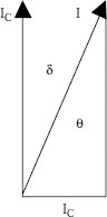
FIGURE 18.2 Phasor diagram for lossy dielectric.
The quantity tan δ is used to designate the lossyness of the insulating dielectric in an AC electric field. This is called loss factor or the tangent of the loss angle δ of the material. Typical values of ev and tan δ are shown in Table 6.1.
For an applied voltage, V, the current through the loss-free dielectric is IC and the current due to the lossyness of the material is IG, see Figure 18.2. The angle formed by the current, I = IC + IG and the current IC is δ. The angle formed by the current, I = IC + IG and the voltage, V, is q and cos q is the power factor. I, IC, and IG are phasor quantities.
The tan δ test is a diagnostic test that allows an evaluation of the cable insulation at operating voltage levels. The test is conducted at operating frequency or at the VLF frequency of 0.1 Hz. When the tan δ measurement exceeds a historically established value for the particular insulation type, the cable is declared defective and will have to be scheduled for replacement. If the tan δ measurements are below a historically established value for a particular insulation type, additional tests have to be performed to determine whether the cable insulation is defective.
Tests conducted on 1,500 miles of XLPE insulated cables have established a figure of merit for XLPE, tan δ = 4 × 10⁻³. If the cables measured tan δ > 4 × 10⁻³, the cable insulation is contaminated by moisture (water trees). The cable may be returned to service, but should be scheduled for replacement as soon as possible. If the cables measured tan δ < 10−3, it is not possible to predict the integrity of the cable insulation. The cable insulation could have many small defects, in which case the cable may operate satisfactorily for many more years. The tan δ should be monitored regularly, and upon further deterioration of the dissipation factor, proper action taken. However, the cable could have only a few isolated large defects, which could cause it to fail upon returning it to service or within days after it has been reenergized. Therefore, if the measured tan δ < 4 × 10⁻³, it is recommended that a VLF test at 3 Vo be performed to identify remove, and repair the large defects.
18.8.4 MEASUREMENT AND EQUIPMENT
Bridge type circuits are used to measure cable capacitance and tan δ. The most common are a Schering bridge and transformer ratio arm bridge. Both test sets require an AC HV source and a loss-free capacitor standard. For balanced bridges, the dissipation factor and cable capacitance are:
Schering bridge
(18.3) |
(18.4) |
Transformer ratio arm bridge
(18.5) |
(18.6) |
• Tan δ measurements are diagnostic tests that permit assessment of the state of aging or damage of the cable insulation.
• Cables are tested with an AC voltage at operating voltage levels.
• The tests are performed at operating or at VLF frequencies.
• The tan δ test can be used on extruded as well as on PILC cables.
• When a cable does not pass the tan δ test, it can still be returned to service until repair or replacement has been scheduled.
• Monitoring of the tan δ will establish a cable history and a deterioration can be observed.
• When a cable passes the tan δ test, it is not possible to declare the cable insulation sound.
• A VLF or breakdown test should be performed to identify any large defects in the cable system insulation.
For typical values of dissipation factor, see Table 6.1.
18.8.7 DISSIPATION FACTOR WITH VERY LOW FREQUENCY SINUSOIDAL WAVE FORM
Bach reported that loss factor (tan δ) measurements at VLF (0.1 Hz sinusoidal) could be used to monitor aging and deterioration of extruded dielectric cables [8]. The 0.1 Hz loss factor is mainly determined by water-tree damage of the cable insulation and not by water along the conducting surfaces. The measurement of loss factor with 0.1 Hz sinusoidal waveform offers comparative assessment of the aging condition of polyethylene, XLPE, and EPR type insulations. The test results permit differentiating between new, defective, and highly degraded cable insulations. The loss factor with a 0.1 Hz with sinusoidal waveform is a diagnostic test. Cables systems can be tested in preventative maintenance programs and returned to service after testing. The dissipation factor measurements at VLF can form the basis for the justification of cable replacement or cable rejuvenation expenditures.
18.8.7.2 Measurement Equipment
A programmable HV VLF test generator with loss factor measurement capability is connected to the cable under test. If for a test voltage of the Vo δ > 4 × 10⁻³, the service aged cables should eventually be replaced. The test voltage should not be raised above Vo in order to prevent insulation breakdown. If for test voltage of Vo the tan δ << 4 × 10⁻³, the service-aged cables should be additionally tested with VLF at 3 Vo for 60 minutes. When the cables pass this test, it can be returned to service without reservation. Loss factor measurements at VLF can form the basis for the justification of cable replacement or cable rejuvenation expenditures.
• The test is a nondestructive, diagnostic test.
• Cables are tested with an AC voltage equal to the phase-to-ground voltage at which they operate.
• Cable system insulation can be graded as excellent, defective, or highly deteriorated.
• Cable system insulations can be monitored and history developed. Cable replacement and rejuvenation priority can be planned.
• Test sets are transportable and power requirements are comparable to standard cable fault locating equipment.
The maximum available test voltage is 36 kV rms and the maximum capacitive load is about 3 μF.
• The test works best after comparative cable system data have been developed.
18.9 VERY LOW FREQUENCY (ABOUT 0.1 HZ) TESTING
VLF testing methods can be categorized as withstand or diagnostic. In withstand testing, insulation defects are caused to breakdown (fault) at the time of testing. Faults are repaired and the insulation is retested until it passes the withstand test. The withstand test is considered a destructive test. Diagnostic testing allows the identification of the relative condition of degradation of a cable system and establishes, by comparison with figures of merit, if a cable system can or cannot continue operation. Diagnostic testing is considered as nondestructive [9].
In extreme cases, when the cable system insulation is in an advanced condition of degradation, the diagnostic tests can aggravate the condition of the cable and cause breakdown before the test can be terminated.
The VLF withstand test methods for cable systems are:
• VLF testing with cosine-pulse waveform
• VLF testing with sine waveform
• VLF testing with square wave with programmable slew rate
The VLF diagnostic test methods for cable systems are:
• VLF dissipation factor (tan δ) measurement
• VLF PD Measurement
Field testing techniques frequently employ a combination of diagnostic and withstand test methods. They are selected based on their ease of operation and cost/benefit ratio. The various VLF test methods described are in commercial use and are accepted as alternate test methods in international standards.
18.9.2 VERY LOW FREQUENCY WITHSTAND TESTING
The Electric Power Research Institute (EPRI) and the Canadian Electrical Association (CEA) funded a study to evaluate the advantages and limitations of 0.1 Hz testing as a possible substitute for DC maintenance testing of in-service, aged power cables [9]. The use of DC was intended to confirm the soundness of a cable and to weed out weakened cables.
The subject of appropriate methods for fault location and maintenance testing of extruded dielectric distribution cables has been given considerable attention. This interest was generated by the knowledge that transient voltages and DC testing can reduce the life of XLPE and TR-XLPE insulated cables. There is an unanswered question as to the effect on EPR cables, but the concern exists.
The laboratory phase of this work evaluated a wide range of insulations and ages of cables. During this laboratory evaluation, various voltages were applied to model cables and service-aged XLPE, 15 kV samples. Similar tests were run on full size EPR, PILC, and transition joints. The results of the study concluded that low frequency AC testing can detect cable imperfections in XLPE cable and transition joints at lower voltages than for a DC test, with none of the detrimental effects of DC.
Once the suitable magnitude and application time of the voltage were determined, field tests were conducted on four utility systems. It was concluded that 0.1 Hz is a satisfactory alternative for DC testing. The shape factor of the 0.1 Hz is the same as the operating system and no damage was found as judged by the decrease in magnitude of AC breakdown. If the circuit fails during the test, the lower test voltage reduces the transient voltages that the system must endure.
Procedures were developed for 0.1 Hz testing of 15 kV cable systems at 22 kV for 15 minutes. Other values are suggested for 5 to 35 kV. A large eastern utility has been using this procedure for several years on mixed cable systems and is very satisfied with the results. Absence of long-term effects on service-aged extruded cables after this test remains to be established.
18.9.3 VERY LOW FREQUENCY TESTING WITH COSINE-PULSE WAVEFORM
The VLF cable test set generates a 0.1 Hz bipolar pulse wave, which changes to sinusoidal polarity. Sinusoidal transitions in the power frequency range initiate a PD at an insulation defect, which the 0.1 Hz pulse wave develops into a breakdown channel. Within minutes, a defect is detected and forced to become a failure. It can then be located with standard, readily available cable fault-locating equipment. Cable systems can be tested in preventative maintenance programs or after a service failure. Identified faults can be repaired immediately and no new defects will be initiated during the testing process. When a cable system passes the VLF test, it can be returned to service.
18.9.3.2 Measurement and Equipment
A DC test set forms the HV source. A DC-to-AC converter changes the DC voltage to the VLF AC test signal. The converter consists of a HV choke and a rotating rectifier that changes the polarity of the cable system being tested every 5 seconds. This generates a 0.1 Hz bipolar wave. A resonance circuit, consisting of a HV choke and a capacitor in parallel with the cable capacitance, assures sinusoidal polarity changes in the power frequency range. The use of a resonance circuit to change cable voltage polarity preserves the energy stored in the cable system. Only leakage losses have to be resupplied to the cable system during the negative half of the cycle.
The 0.1 Hz test set is easily integrated in a standard cable fault-locating and cable-testing system by making use of available DC high potential sets. Stand-alone VLF systems should be supplemented by cable fault-locating equipment.
The cable system to be tested is connected to the VLF test set. In five to six steps, the test voltage is regulated to the test voltage level of 3 Vo (Vo is phase-to-ground voltage). The recommended testing time is 15 to 60 minutes. When the cable system passes the VLF voltage test, the test voltage is regulated to zero and the cable and test set are discharged and grounded. When a cable fails the test, the VLF test set is turned off to discharge the system. The fault can then be located with standard cable fault-locating equipment.
• The VLF test uses a 0.1 Hz pulse wave that changes to sinusoidal polarity. The sinusoidal transitions in the power frequency range may initiate a PD at a defect that the 0.1 Hz pulse wave may develop into a breakthrough channel.
• Due to sinusoidal transitions between the HV pulses, traveling waves are not generated.
• Due to continuous polarity changes, dangerous space charges cannot develop. Cables can be tested with an AC voltage up to three times the conductor-to-ground voltage with a device comparable in size, weight, and power requirements to a DC test set.
• The VLF test can be used on extruded as well as oil impregnated paper insulations.
• The VLF test with cosine-pulse waveform works best when eliminating a few singular defects from an otherwise good cable insulation. The VLF test is used to “fault” the cable defects without jeopardizing the cable system integrity.
• When a cable passes the recommended 0.1 Hz VLF test, it can be returned to service.
• When testing cables with extensive water-tree damage or ionization of the insulation, VLF testing alone is often “not conclusive.” Additional tests that measure the extent of insulation losses will be necessary.
• Present limitations are the maximum available test voltage of 56 kV.
18.9.4 VERY LOW FREQUENCY TESTING WITH SINUSOIDAL WAVEFORM
The VLF test set generates sinusoidal changing waves that are less than 1 Hz. When the local field strength at a cable defect exceeds the dielectric strength of the insulation, PD starts. The local field strength is a function of applied test voltage, defect geometry, and space charge. After initiation of PD, the PD channels develop into breakthrough channels within the recommended testing time. When a defect is forced to break through, it can then be located with standard, readily available fault locating equipment. Cable systems can be tested in preventative maintenance programs after failure. Identified faults can be repaired immediately. When a cable passes the VLF test, it can be returned to service.
18.9.4.2 Measurement and Equipment
The VLF test set is connected to the cable or cable system to be tested. The test voltage is regulated to the test voltage level of 3 Vo. The recommended testing time is 60 minutes or less than that found in VLF testing guides. VLF sets that have sufficient capacity to be able to supply and dissipate the total cable system charging energy can be found. When the cable system passes the VLF voltage test, the test voltage is regulated to zero and the test set and cable system are discharged and grounded. When a cable fails the test, the VLF test is turned off to discharge the cable system and test set and the cable fault can then be located with standard cable fault-locating equipment.
In addition to standard 0.1 Hz sinusoidal VLF test sets, which have been in use for many years for VLF testing of electrical machines, several variations are also available to meet specific cable system test requirements:
1. VLF, less than 0.1 Hz, high-voltage generator with programmable test voltage waveforms for cable systems with mixed insulation:
a. Sine wave test voltage
b. Bipolar pulse wave with defined slew rate
c. Regulated DC test voltage with positive and negative polarities
d. Programmable step test for all voltage waveforms
2. VLF, 0.1 Hz, HV generator with dissipation factor (tan δ) measurement capability
3. PD free, VLF, 0.1 Hz HV generator for PD testing
4. PD free, VLF, bipolar pulse with defined slew rate, HV generator for PD testing
• Cables are tested with an AC voltage up to three times the conductor-to-ground voltage. After initiation of a PD, a breakthrough channel at a cable defect develops.
• Due to continuous polarity changes, dangerous space charges do not develop in the cable insulation.
• Test sets are transportable and power requirements are comparable to standard cable fault-locating equipment.
• The VLF test can be used on extruded as well as paper-type cable insulations. The VLF test with sinusoidal waveform works best when eliminating a few defects from an otherwise good cable insulation. The VLF test is used to “fault” the cable defects without jeopardizing the cable system integrity. When a cable passes the recommended 0.1 Hz VLF test, it can be returned to service.
• VLF test sets with 0.1 Hz loss factor measurement capability for diagnostically identifying cables with highly degraded cable insulations are available and can be used with a 0.1 Hz withstand test.
• When testing cables with extensive water-tree damage or ionization of the insulation, VLF withstand testing alone is often “not conclusive.” Additional tests that measure the extent of insulation losses will be necessary.
• Limitations are the maximum available test voltage of 36 kV rms and the maximum capacitive load of approximately 3 μF at 0.1 Hz (30 μF at 0.01 Hz). The total charging energy of the cable has to be supplied and dissipated by the test in every electrical period. This limits the size of the cable system that can be tested. A long testing time must be seen as an inconvenience rather than a limitation.
18.9.5 TAN δ TEST WITH VLF SINUSOIDAL WAVEFORM
Bahder [18] first used dissipation factor (tan δ) measurements to monitor aging and deterioration of extruded dielectric cables. Bach reported a correlation between an increasing 0.1 Hz dissipation factor and a decreasing insulation breakdown voltage level at power frequency. The 0.1 Hz loss factor is mainly determined by water-tree damage of the cable insulation and not by water along the conducting surfaces. The measurement of the loss factor with a 0.1 Hz sinusoidal waveform offers comparative assessment of the aging of polyethylene, XLPE, and EPR type insulations. The test results permit differentiation between new, defective, and highly degraded cable insulations. The loss factor with a 0.1 Hz sinusoidal waveform can be used as a diagnostic test. Cables can be tested in preventative maintenance programs and returned to service after testing. The loss factor measurements at VLF can be used to justify cable replacement or cable rejuvenation expenditures.
18.9.5.2 Measurement and Equipment
A programmable, HV VLF, 0.1 Hz test generator with dissipation factor measurement capability is connected to the cable system under test. The dissipation factors of tan δ at Vo, tan δ at 2 Vo, and the differential loss factor Δ tan δ (tan δ at 2 Vo minus tan δ at Vo) are measured. The measured values are used as figures of merit to grade the condition of the cable insulation as good, defective, or highly deteriorated.
For example, XLPE insulation is tested at a 0.1 Hz test voltage of Vo and the tan δ > 2 × 10⁻³, the service-aged cables should be replaced. The test voltage should not be raised above Vo in order to prevent an insulation breakdown. If for a 0.1 Hz test voltage of Vo, and the tan δ >> 1.2 × 10⁻³, the service-aged cables should additionally be tested with VLF 3 × Vo for 60 minutes. When cable passes this test, it can be returned to service.
If for a 0.1 Hz test voltage at Vo and 2 Vo, the loss factors are 1.2 × 10⁻³ < tan δ < 2 × 10⁻³ and the differential loss factor Δ tan δ < 0.6, the cable should be returned to service but monitored semiannually.
If for a 0.1 Hz test voltage at Vo and 2 Vo, the loss factors are 1.2 × 10⁻³ < tan δ < 2 × 10⁻³ and the Δ tan δ > 1.0, the cable should be replaced.
It must be understood that, for different insulations, installations, and cable types, tan δ figures of merit can vary significantly from the values listed in the previous paragraph. The test gives the best results when comparing present measurements against established historical figures of merit for a particular cable.
• This test is a diagnostic, nondestructive test. Cable systems are tested with an AC voltage equal to the conductor-to-ground voltage.
• Cable system insulation can be graded between good, defective, and highly deteriorated.
• Cable system insulation condition can be monitored over time and a cable system history be developed. Cable replacement and cable rejuvenation priority and expenditures can be planned.
• Test sets are transportable and power requirements are comparable to standard cable fault-locating equipment.
• For a 0.1 Hz VLF test set, the maximum available test voltage is 36 kV rms and the maximum capacitive load in approximately 3 μF.
• The test becomes useful after historical comparative cable system data have been accumulated.
The suitability, practicality, and effectiveness of these testing methods for service-aged power cables with extruded dielectric insulation should be determined based on experience.
It is known that DC testing of extruded dielectric insulated cables is not very useful. In fact, it may cause cables to fail after having been returned to service. At this time, VLF test techniques are effective alternatives for testing of service-aged power cables with extruded dielectric insulation.
OSW testing, also known as damped alternating current (DAC) testing [5], was selected by a CIGRE task force “alternative tests after laying” as an acceptable compromise using the following criteria:
• The ability to detect defects in the insulation that will be detrimental to the cable system under service conditions, without creating new defects or causing aging
• The degree of conformity between the results of tests and the results of 50 or 60 Hz tests
• The complexity of the testing method
• The commercial availability and costs of the testing equipment
The purpose of the OSW testing method is to detect defects that may cause failures during service life without creating new defects that may threaten the life of the cable system.
Although OSW testing does not have a wide reputation with respect to cable testing, it is already used for testing in metal-clad substations and is being recommended for gas insulated cable testing.
18.10.2 GENERAL DESCRIPTION OF TEST METHOD
The test circuit basically consists of a DC voltage supply, which charges a capacitance C1, and a cable capacitance C2. After the test voltage has been reached, the capacitance is discharged over an air coil with a low inductance. This causes an oscillating voltage in the kilohertz range. The choice of C1 and L depends on the value of C2 to obtain a frequency between 1 and 10 kHz.
• The OSW method is based on an intrinsic AC mechanism.
• The principal disadvantages of DC (field distribution, space charge) do not occur.
• The method is easy to apply.
• The method is relatively inexpensive.
• Effectiveness of the OSW test method in detecting defects is better than with DC but worse when compared with AC (60 Hz).
• In particular for medium voltage cable systems, the factor f* OSW/60 Hz voltage approaches 1, indicating the mutual equivalence.
• For HV cable systems f* OSW/60 Hz is significantly higher (1.2 to 1.9), which means that OSW is less effective than 60 Hz.
• For both HV and MV cable systems, f* OSW/DC is low (0.2 to 0.8), indicating the superiority of OSW over DC voltage testing.
• Since the capacitance of a cable is dependent on length, each length of otherwise identical cable, for instance, oscillates at a different frequency. This difference in frequency creates a change in measured properties. [Note: f* OSW/60 Hz is the ratio of breakdown values for a dielectric containing a standard defect when using OSW voltage and 60 Hz voltage, respectively.]
The cable is charged with a DC voltage and discharged through a sphere gap into an inductance of appropriate value so as to obtain the desired frequency. The voltage applied to the cable is expressed by:
(18.7) |
where
V1 = charging voltage provided by the generator
α = damping ratio
C = C1 + C2
Other test circuits are possible and give alternative solutions using different circuit configurations.
Many tests carried out so far are of an experimental nature. Artificial defects like knife cuts, wrong positions of joints and holes in the insulation were created and subjected to different testing procedures including the OSW testing method.
These test procedures were intended to obtain breakdown as a criterion for comparison. The general testing procedure is as follows:
• Start to charge the cable with a DC voltage of about one or two times the operating voltage.
• Increase with steps of 20 to 30 kV.
• Produce 50 shots at each voltage level.
• Time interval between shots 2 to 3 minutes.
• Proceed until breakdown occurs.
In one case, the Dutch testing specification for HV extruded cables, the OSW method is mentioned as a withstand test to be used as an after-laying (installation) test. The test procedure is as follows:
• Charge the cable slowly, using the DC power supply.
• After reaching the value of 3 Vo, the DC source will be disconnected and the rapid recloser activated.
• The cable circuit will be discharged through a reactor, causing the OSW testing voltage.
• This procedure should be repeated 50 times.
In the Netherlands, the OSW testing method is applied as an after-laying test for HV extruded cable systems.
18.10.7 FURTHER DEVELOPMENT WORK
Since the effectiveness of the OSW testing method is not as high as would be desired, it might be very attractive to combine OSW with PD site detection as an additional source of information. In the literature, details are given of an automatic PD measurement system, enabling statistical analysis and generating phase, time, and amplitude resolved PD fingerprints. Compared to AC 50/60 Hz generated PD fingerprints, additional information results from the decreasing voltage amplitude of each OSW pulse. For medium voltage cable systems according to [12], this measuring system looks feasible.
Dielectric spectroscopy is one of several test methods to measure dielectric losses in a cable system [16,17]. The proponents believe that PD activity from internal cavities and surface discharges are the main cause of aging. This measurement can provide information on the global effects caused by water treeing and oxidation of the insulation.
The general approach is to separate any “noise” from the PD patterns. The measurement is based on the response of the insulation when subjected to ever increasing voltages over a wide frequency range:
• If the response is linear, there is little or no aging.
• If the response is nonlinear, the cable is aged and deteriorated.
The significance of the deterioration is determined from the magnitude of response. The frequency range is from 0.0001 kHz to 1 kHz and the voltage for XLPE is from 0 to 20 kV peak.
1. IEEE Std 400-2001, “Guide for Field Testing and Evaluation of Shielded Power Cables”, SH94972.
2. IEEE Std 400.1-2007 (previously IEEE 400-1991), “Guide for Field Testing Laminated Dielectric, Shielded Power Cable Systems Rated 5 kV and Above With High Direct Current Voltage”.
3. IEEE Std 400.2-2005, “Guide for Field Testing of Shielded Power Cable Systems Using Very Low Frequency”.
4. IEEE Std 400.3-2007, “Guide for PD Testing of Shielded Power Cable Systems in a Field Environment”.
5. IEEE Std 400.4 (under development), “Guide for Field Testing of Shielded Power Cabled Systems Rated 5 kV and Above with Damped Alternating Current Voltage (DAC).”
6. Srinivas, N. H., et al., June 1991, “Effect of DC Testing on Aged XLPE Insulated Cables with Splices”, JICABLE 91, Paris, France.
7. Eager, G. S., Jr., et al., July 1992, “Effect of DC Testing Water Tree Deteriorated Cable and a Preliminary Evaluation of VLF as an Alternative”, IEEE Transactions on Power Delivery, Vol. 7 (No. 3).
8. Bach, R., 1989, “Quervergleich Verschiedener Spannungarten zur Pruefung von Mittelspannungs Kabelanlagen”, (in German), Technical University of Berlin, Annual Report of Research Activities.
9. Report TR-110813, “High Voltage, Low Frequency (0.1 Hz) Testing of Power Cables”, EPRI, Palo Alto, CA and Canadian Electrical Association, Montreal, Quebec, July 1998.
10. AEIC CG7-2005, “Guide for Replacement and Life Extension of Extruded Dielectric 5–35 kV Underground Distribution Cable”, Second Edition.
11. IEEE 510-1992, IEEE Recommended Practices for Safety in High-Voltage Power Testing, reaffirmed 1992.
12. IEEE 4-2001, IEEE Standard Techniques for High-Voltage Testing.
13. IEEE 48-2009, IEEE Standard Test Procedures and Requirements for High-Voltage Alternating-Current Cable Terminations.
14. Ahmed, N. and Srinivas, N., 1998, “On Line Partial Discharge Detection in Cables”, IEEE Dielectrics and Electrical Insulation, Vol. 5 (No. 2).
15. Srinivas, N., Nishioka, T., Sanford, K., and Bernstein, B., 2006, “Non Destructive Condition Assessment of Energized Cable Systems”, IEEE/PES Transmission and Distribution Conference, Dallas, TX.
16. Werelius, P., Tharning, P., Erikson, R., Holmgren, B. and Gafvert, U., February 2001, “Dielectric Spectroscopy for Diagnosis of Water Treed Deterioration in XLPE Cables”, IEEE Dielectrics and Electrical Insulation, Vol. 1, pp. 27–41.
17. Reiter, M. Gockenbach, E. and Bursi, H., “Dielectric Spectroscopy of Multi-stress Aged XLPE Insulation of Synergistic Effects”, Proceedings of the 2005 International Symposium of Electrical Insulation Materials, Vol. 1, ISEM 2005.
18. Baher, G., et al., 1977, “In Service Evaluation of Polyethylene and Cross-Linked Polyethylene Insulated Cables Rated 15 to 35 kV”, IEEE Transactions Power Apparatus and Systems, PA&S-96, pp. 1754–1766.