
The battery voltage can be monitored using an Arduino analog input, but you can't directly connect the battery to an input pin because a fully charged battery can exceed the maximum voltage that the Arduino chip can tolerate.
Another factor to be aware of is that the default voltage reference for
analogRead is the 5 volt output from the regulator on the Arduino board.
This regulator requires more than 6 volts to produce a stable 5 volt output. When the voltage
difference between the regulator input and output (referred to in the regulator datasheet as
the dropout voltage) is less than a volt, the output voltage will drop below the required 5
volt level. Because this voltage is used as the default Arduino reference for analog
conversion, the analog readings will no longer be accurate. In short, you shouldn't rely on
the battery voltage as a reference to measure the battery voltage. So you need a reliable
voltage reference that is not dependent on the output from the regulator.
The solution is to use an internal voltage reference that is built into the Arduino chip. This provides a 1.1 volt reference that is stable for any voltage that is sufficient to power the Arduino chip. Because the reference is 1.1 volts, the voltage being measured must not exceed this value, so a voltage divider to drop battery voltage down to an acceptable range is required (Figure D-1).
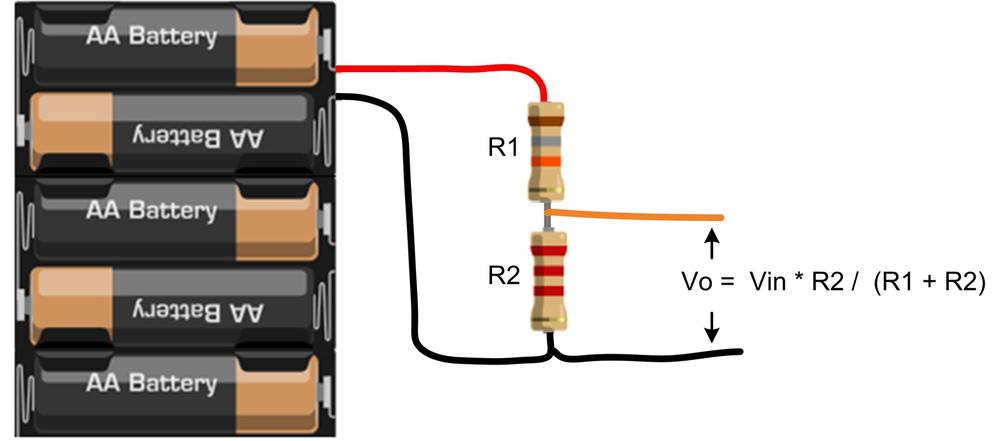
To support a wide range of battery choices (including 8.4 volt LiPo batteries), resistor values of 18k ohms for R1 and 2.2k ohms for R2 provide a voltage range of up to 10 volts.
Note
Here is the voltage divider formula for these resistor values: R2 / R1
+ R2. Substituting the chosen values results in:
2200/(18000 + 2200)
= 0.109
Therefore the voltage on the terminal will be the battery voltage times 0.109. For example, 10 volts at the battery will be dropped to just under the 1.1 volt range of the internal reference.
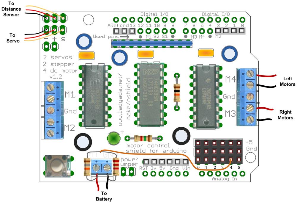
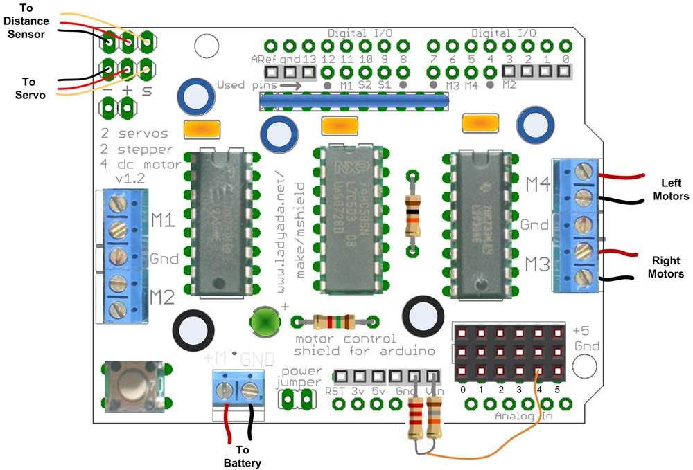
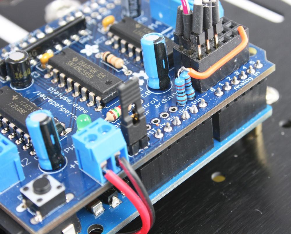
The resistors can be attached to the battery terminals as shown in Figure D-2, but a more permanent solution is to solder the resistors to the shield as shown in Figure D-3 and Figure D-4.
The code to read and interpret the voltage is in the Battery tab (Example D-1).
This code reads the output of the voltage divider using analogRead and
converts this into the battery voltage expressed in millivolts. This is compared to preset
thresholds levels so an LED can be flashed to indicate low and critical battery levels. The
code can also detect if the optional charger plug is connected to stop robot movement while
being recharged.
Example D-1. Battery tab code
// code to monitor battery voltage

/******************************************************************
 * LED starts flashing when volage drops below warning level
 * mark space ratio increses from 10% to 50% as voltage decreses from warning to critical
 * robot shuts down when battery below critical and led flashes SOS
 *
 * LED mark space ratio changes from 10% to 90% as voltage increases to full
 *****************************************************************/


// thresholds are the cell millivolts times number of cells
const int batteryFull    =  1500 * 5; // threshold for battery is low warning
const int batteryWarning =  1100 * 5; // threshold for battery is low warning
const int batteryCritical=  1000 * 5; // threshold to shut down robot

int batteryMonitorPin;    // analog pin to monitor
int chargerDetectPin =-1; // pin goes open circuit when charger connected, default is no pin
int blinkPin;             // led pin to flash


void batteryBegin(int monitorPin, int ledPin)
{
  batteryMonitorPin = monitorPin;
  blinkPin = ledPin;
  pinMode(blinkPin, OUTPUT);
}

// version for charger detection
void  batteryBegin(int monitorPin, int ledPin, int chargerPin)
{
  batteryBegin(monitorPin, ledPin);
  chargerDetectPin = chargerPin;
  pinMode(chargerDetectPin, INPUT_PULLUP); // connect pull-up resistor
}

// indicates battery status using the given LED
void  batteryCheck()
{
  int mv = batteryMv(batteryMonitorPin); // get battery level in millivolts
  Serial.print("mv="); Serial.print(mv);
  if(chargerDetectPin >=0 &&  digitalRead(chargerDetectPin) == HIGH)
  {
    // here if charger detect is enabled and charger plugged in
    while( digitalRead(chargerDetectPin) == HIGH) // while charger is plugged in
    {
        moveStop();
        mv =  batteryMv(batteryMonitorPin); // get battery level in millivolts
        Serial.print(", charger detected, voltage=");
        Serial.println(mv); Serial.println(", percent=");
        int percent = map(mv, batteryCritical, batteryFull, 50, 100);
        percent = constrain(percent, 0, 100);
        Serial.println(percent);
        flash(percent, blinkPin);
    }
  }
  else
  {

    if(mv < batteryCritical)
    {
      Serial.println("Critical");
      // shut down the robot
      moveStop();
      while(1) {
        flashCritical(blinkPin);
        // check of the charger is plugged in
        if(chargerDetectPin >=0 && digitalRead(chargerDetectPin) == HIGH)
           return; // exit if charging

        delay(5000);
     }
    }
    else if (mv < batteryWarning)
    {
      int percent = map(mv, batteryCritical, batteryWarning, 10, 50);
      flash(percent, blinkPin);
    }
  }
  delay(1000);
  Serial.println();
}

// return the voltge on the given pin in millivolts
// see text for voltage divider resistor values
int  batteryMv(int pin )
{
#if defined(__AVR_ATmega32U4__) // is this a Leonardo board?
  const long INTERNAL_REFERENCE_MV = 2560; // leo reference is 2.56 volts
#else
  const long INTERNAL_REFERENCE_MV = 1100; // ATmega328 is 1.1 volts
#endif
  const float R1 = 18.0;  // voltge dividier resistors values, see text
  const float R2 = 2.2;
  const float DIVISOR = R2/(R1+R2);

  analogReference(INTERNAL);      // set reference to internal (1.1V)
  analogRead(pin);  // allow the ADC to settle
  delay(10);

  int value = 0;
  for(int i=0; i < 8; i++) {
    value = value + analogRead(pin);
  }
  value  = value / 8; // get the average of 8 readings
  int mv = map(value, 0,1023, 0, INTERNAL_REFERENCE_MV / DIVISOR );

  analogReference(DEFAULT); // set the reference back to default (Vcc)
  analogRead(pin); // just to let the ADC settle ready for next reading
  delay(10); // allow reference to stabalise

  return mv;
}

// flashes SOS in morse code
void flashCritical(int pin)
{
  for(int i=0; i< 3; i++)
    flash(20, pin);
  for(int i=0; i< 3; i++)
    flash(60, pin);
  for(int i=0; i< 3; i++)
    flash(20, pin);
}


// percent is the percent of on time time (duty cycle)
void flash(int percent, int pin)
{
  Serial.print(", flash percent="); Serial.println(percent);
  const int duration = 1000;
  // Blink the LED
  digitalWrite( pin, HIGH);
  int onTime = map(percent, 0, 100, 0, duration);
  delay(onTime);
  digitalWrite( pin, LOW);
  delay(duration - onTime);
}
There are two versions of the batteryBegin function. Use the one with
three parameters if you have wired up the trickle charger circuit. The three parameters
passed to the function are: the pin that the voltage divider is connected to, the LED pin,
and the pin that detects the charger plug. Here is the function:
batteryBegin(alogBatteryPin, ledPin, chargerDetectPin)
If you have not wired the robot to use a charger, then call
batteryBegin with two parameters: the pin that the voltage divider is
connected to and the LED pin:
batteryBegin(alogBatteryPin, ledPin)
The checking is done in the batteryCheck function. This gets the
battery level in millivolts by calling batteryMv and compares this to the
warning and critical thresholds. The LED is flashed when the level drops below the warning
level with a flash ratio (blink on time to off time) that changes as the voltage drops. If the
voltage drops below the critical level, the robot movement is stopped, and the LED flashes a
distress signal (SOS in morse code) every 5 seconds. When this happens, the batteries must be
replaced or recharged before the robot will reactivate.
The myrobotBatteryMonitor example sketch (Example D-2) in the download shows how to
use the battery monitor function.
Example D-2. Battery monitor example sketch
/******************************************************************************
myRobotBatteryMonitor.ino

sketch to demonstrate battery voltage monitoring
based on myRobotWander

Robot wanders using forward scanning for obstacle avoidance
LED blinks when battery runs low, robot goes to sleep when battery is critical.

Created by Michael Margolis 22 July 2012
******************************************************************************/
#include "robotDefines.h"  // global defines

#include <AFMotor.h>  // adafruit motor shield library
#include "RobotMotor.h"    // 2wd or 4wd motor library

const int ledPin = 13;          // onboard LED
const int alogBatteryPin = 5;   // input on analog 5
const int chargerDetectedPin = 2; // digital pin 2

// Setup runs at startup and is used configure pins and init system variables
void setup()
{
  Serial.begin(9600);
  blinkNumber(8); // open port while flashing. Needed for Leonardo only

  lookBegin();
  moveBegin();
  //batteryBegin(alogBatteryPin, ledPin);
  batteryBegin(alogBatteryPin, ledPin, chargerDetectedPin);

  pinMode(ledPin, OUTPUT);
  Serial.println("Ready");
}

void loop()
{
//  roam();
  batteryCheck();
}

// function to indicate numbers by flashing the built-in LED
void blinkNumber( byte number) {
   pinMode(LED_PIN, OUTPUT); // enable the LED pin for output
   while(number--) {
     digitalWrite(LED_PIN, HIGH); delay(100);
     digitalWrite(LED_PIN, LOW);  delay(400);
   }
}
The build chapters in the beginning of the book described a simple trickle charger that you can use to recharge NiMH batteries. This section describes how to use the charger as well as some important points to ensure that you don't damage your batteries.
Trickle charging is a method of recharging NiMH batteries that provides a slow but steady charging current which should fully recharge 5 AA cells in around 14 to 16 hours. The charger has been designed for cells with a rated capacity of 2000 to 2500 mAh (milliampere hours). Cells with a higher rating can be used but they will require a longer charging period.
Warning
Do not try to charge non-rechargeable batteries.
The batteries start charging when a DC power supply is plugged into the charging socket and the power switch is turned on. The charging circuit is designed for use with a 12 volt supply with a 2.1mm plug (positive on the center connector). Cells with the suggested rating should handle the trickle charge current for long periods, however it is good practice to keep your charge session to 24 hours or less, particularly if your DC supply could be delivering a little more than the recommended 12 volts.