
Now that you’re a rectangle-drawing champion, you’ll draw some other shapes and put them to good use. What better way to practice basic drawing than by creating a holiday card?
Through the metaphor of a paper collage, you’ll learn how to compose an image using shapes and lines in Processing. I’ll also give you a deeper look at the line() function and how you can modify lines in different ways. Put on your artist’s hat, because here we go!
GATHER YOUR MATERIALS
• Colored pencils
• Graph paper
DRAWING MORE SHAPES!
You can draw a number of basic shapes in Processing, and each shape is always defined by points on the Cartesian coordinate plane. Here is a rundown of the basic geometric shapes and the parameters that you need to pass to them.
Ellipses
An ellipse is an oval or circle, and you can draw one in Processing with the ellipse() function. Pass ellipse() four values, just like you would rect(), in this order:
ellipse(X,Y,W,H);
X and Y give the x- and y-coordinates of the ellipse’s position; W and H indicate the width and height, respectively. If you make W and H the same value, you’ll draw a circle, as in this example.
void setup()
{
size(250,250);
background(150);
}
void draw()
{
❶ ellipse(125,125,100,100);
}
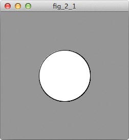
In this sketch, I’ve used ellipse() ❶ to draw a circle with a diameter of 100 pixels at the center of the sketch window (see Figure 2-1).
FIGURE 2-1: Drawing an ellipse in Processing
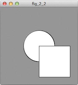
The difference between drawing a rectangle and drawing an ellipse is that the rectangle’s origin is its upper-left corner, while the ellipse’s origin is its center. You can see this clearly in Figure 2-2, where both a rectangle and an ellipse have been passed the same parameters.
FIGURE 2-2: This ellipse and rectangle were both passed the parameters (100,100,100,100). Try it!
Lines
The second common shape you’ll draw in Processing is the line. You used the line() function in Project 0, but I’ll cover it in a little more detail here. The line() function requires two points, (X1,Y1) and (X2,Y2). The order of parameters in the line() function is as follows:
line(X1,Y1,X2,Y2);
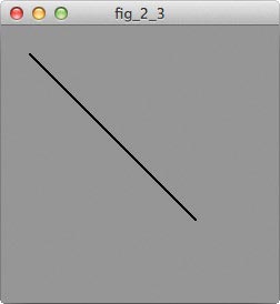
The first point, (X1,Y1), indicates where your line should start. The second, (X2,Y2), indicates where it should end. So in this example, I’ve drawn a line from (25,25) to (175,175):
This line should run from the top left to the bottom right of the sketch window, as shown in Figure 2-3.
FIGURE 2-3: Drawing a line
Line Color
The stroke() function, which you learned about in Project 1, doesn’t just change shape outlines; it modifies the line() function, too. So to change the color of a line, use the stroke() function and pass it a set of RGB values. The noStroke() function also hides all lines as well as outlines. Keep that in mind for later!
stroke(R,G,B);
noStroke();
You can change the stroke color as many times as you want in your sketch:
void setup()
{
size(250,250);
background(150);
}
void draw()
{
❶ stroke(255,0,0);
line(0,0,200,200);
❷ stroke(0,255,0);
❸ stroke(0,0,255);
line(100,0,200,100);
}
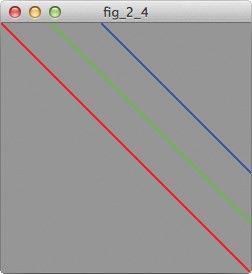
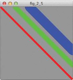
In this example, I’ve drawn a red line ❶, a green line ❷, and a blue line ❸ on a gray background. Check out the result in Figure 2-4.
FIGURE 2-4: Pick a color, any color!
Line Thickness and End Shapes
More useful, line-specific modifiers include strokeWeight() and strokeCap(). strokeWeight() controls the thickness of a line, and you pass it one parameter—the line thickness in pixels:
strokeWeight(width in pixels);
There is no limit to your strokeWeight() value, but past a certain weight, it would probably be easier to use the rect() function. I’ve shown a few examples here:
void setup()
{
size(250,250);
background(150);
}
void draw()
{
stroke(255,0,0);
❶ strokeWeight(5);
line(0,0,200,200);
stroke(0,255,0);
❷ strokeWeight(15);
❷ strokeWeight(30);
line(100,0,200,100);
}
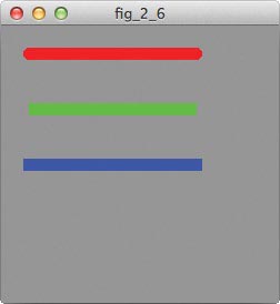
In this sketch, the red line ❶ has the smallest stroke weight, so its line is the thinnest. The green line ❷ and the blue line ❸ are progressively larger, as shown in Figure 2-5.
FIGURE 2-5:
Each line has a different strokeWeight() value.
strokeCap() deals with the shape of the end of a line. You have three different shapes to choose from: ROUND, SQUARE, and PROJECT. (You must capitalize these parameters for the function to accept them; this formatting denotes that they are a known and preset parameter within Processing.)
strokeCap(ROUND);
strokeCap(SQUARE);
strokeCap(PROJECT);
As their names indicate, ROUND rounds off the end of a line, and SQUARE gives your line a squared-off end. Both terminate the line at exactly the point specified by line(). PROJECT is a squared line that projects a distance beyond the point, for some extra style. Look at these stroke caps in action:
❶ strokeCap(ROUND);
line(25,25,175,25);
stroke(0,255,0);
strokeWeight(10);
❷ strokeCap(SQUARE);
line(25,75,175,75);
stroke(0,0,255);
strokeWeight(10);
❷ strokeCap(PROJECT);
line(25,125,175,125);
}
These three lines all start and stop at the same x-positions, but they look a bit different. The red line ❶ is rounded, while the green line ❷ is squared off. The blue line ❸ looks like another square-capped line, but it projects a bit farther than the green line. You can see this output in Figure 2-6.
FIGURE 2-6: Each line uses a different strokeCap()type.
Quadrilaterals
Quadrilaterals are another shape you’ll see used frequently in Processing. While the rect() function is great for drawing rectangles and squares, quad() is much more flexible. It also produces a shape with four sides, but those sides don’t need to be parallel to one another, as they do in a rectangle or square. You pass the quad() function eight parameters, which represent the four corner points of the shape:
quad(X1,Y1,X2,Y2,X3,Y3,X4,Y4);
Make sure you specify the points of the quadrilateral in sequential order, because Processing will draw from point to point. You can go around the shape either clockwise or counterclockwise, starting from (X1, Y1).
void setup()
{
size(250,250);
background(150);
}
void draw()
{
fill(255,0,0);
❶ quad(25,25,150,50,100,175,25,200);
}
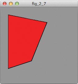
To draw the shape in Figure 2-7, I started with the point closest to the top left (25,25) and went clockwise to (150,50), and so on ❶.
FIGURE 2-7: A proper quadrilateral has four sides, but they don’t have to be parallel.
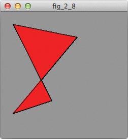
If you don’t enter your points in order, you may get an odd-looking shape instead of a quadrilateral. Figure 2-8 shows an example where I swapped the last two points around. Not quite what I was looking for!
FIGURE 2-8: Swapping two points actually produced two triangles!
The final common Processing shape I’ll cover here is a triangle. The triangle() function requires three points, so it takes six different parameters:
triangle(X1,Y1,X2,Y2,X3,Y3);
As with the quad() function, you need to pick a direction and follow it around the shape as you pass in those points:
void setup()
{
size(250,250);
background(150);
}
void draw()
{
fill(0,255,0);
triangle(25,25,150,50,25,200);
}
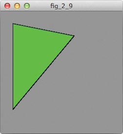
This sketch should draw the triangle in Figure 2-9, starting at (25,25) and moving clockwise around the shape.
FIGURE 2-9: One bright green triangle coming up!
If you have trouble thinking in terms of points in space and then connecting those points, I recommend keeping graph paper and a pencil on hand as you get started with Processing. When you use quad() and triangle(), it helps to sketch out your drawing on graph paper to get your points straight before typing the parameters.
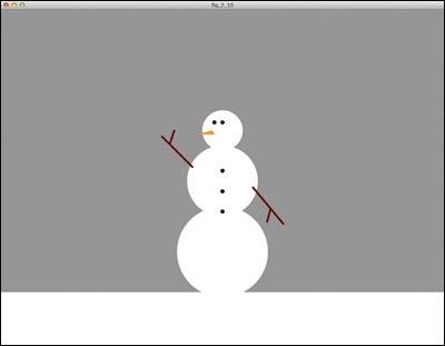
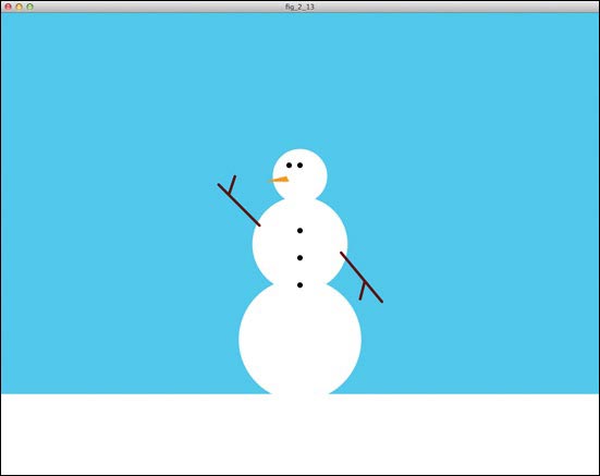
Time to start drawing! As I mentioned in the introduction, you can think of the sketch window as a collage. Remember cutting out paper circles and gluing them to a piece of construction paper to create a card before winter break when you were a kid? You’re going to do the same thing in Processing, but with a lot less mess. In this project, you’ll make a snowman like the one in Figure 2-10, but once you have a sense of how shapes and lines work together, you can draw anything you want!
FIGURE 2-10:
A snowman created using shapes and lines in Processing
Setting the Stage
Your code window is probably full of practice code, so click File ![]() New to open a clean window now.
New to open a clean window now.
Going back to that collage metaphor, the first thing you need is a piece of digital construction paper. You’ve seen the size() and background() functions already in Project 1, and you’ll use them here to create a light blue sky background.
void setup()
{
size(1100,850);
background(25,220,252);
}
This setup() function gives you a big, blue canvas on which you can draw your snowman scene.
With the setup() function in place, you can start to add shapes. I suggest drawing the snowman from the bottom layer up, as if you were building a real one. First, create the body of the snowman by adding the following after your setup() code:
void draw()
{
fill(255);
noStroke();
❶ rect(0,700,1100,150);
ellipse(550,600,225,225);
ellipse(550,425,175,175);
ellipse(550,300,100,100);
//accessorize your snowman here!
noLoop();
}
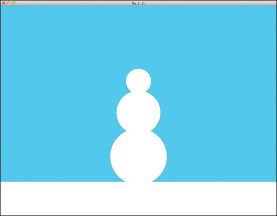
In this code, I added the ground as a rectangle ❶ and stacked three white ellipses on top of one another, as shown in Figure 2-11. I also placed the example snowman in the center of the sketch window, as indicated by the fact that all three ellipses have an x-coordinate of half the total sketch width.
FIGURE 2-11: The body of your snowman uses three different-sized ellipses.
I went with the standard three-ball snowman, but if you have other ideas for your snowman’s body shape, try them out! You’ll find drawing a graph paper sketch first invaluable there, too. Then you can draw as many trial snowmen as you want before you decide which to plug into Processing.
Also, notice the noLoop() function at the end of the draw() loop. Normally, draw() repeats over and over again, but once you glue shapes to your paper, your physical collage is static, so that’s how you’ll approach the digital one, too. The noLoop() function prevents draw() from repeating.
I played around with the sizes of the different ellipses until I found a size and scale I liked for each. If you have trouble visualizing the different components of the sketch at this point, rough out a snowman on your graph paper first. Be sure to note where the origins of your circles fall and the rough endpoints of your lines. If you lack time or patience, graph paper will help you conserve both.
With the snowman’s body in place, you can add some distinguishing features. A standard snowman has three buttons, two eyes, and a carrot nose. Those will be our next phase of programming, so add the following just before the closing bracket of your draw() loop, underneath the three ellipses:
fill(0);
ellipse(530,280,10,10);//eyes
ellipse(550,280,10,10);
ellipse(550,400,10,10);//buttons
ellipse(550,450,10,10);
ellipse(550,500,10,10);
fill(255,150,0);
triangle(525,300,530,310,485,310);//carrot nose
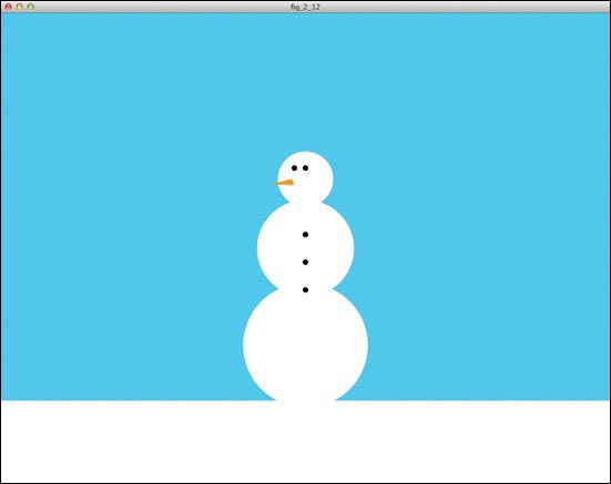
In my code, I grouped the eyes and buttons together under the black fill() function and drew the carrot nose last. As you learned in Project 1, grouping the shapes and lines by color reduces the number of fill() and stroke() functions you have to use. See the output in Figure 2-12. That’s progress!
For the arms of my snowman, I used a number of lines to create sticks. To draw arms like the ones I used, add the following immediately after the code for your snowman’s nose:
❶ stroke(100,15,15);
❷ strokeWeight(5);
line(475,390,400,315); //right arm
line(419,333,430,300);
line(625,440,700,530); //left arm
line(668,494,660,525);
FIGURE 2-12: It’s clear that you’re making a snowman, but this holiday card isn’t done yet.
I changed the stroke color to brown ❶ and increased the stroke weight ❷ to make the sticks thicker. You could also play with the strokeCap() of your lines to get the look you want; I stuck with the standard cap, as you can see in Figure 2-13.
FIGURE 2-13: Your snowman is complete!
Review the snowman code so far and look over all of the geometric shape functions and their modifiers. I used a lot of exact numbers in my points, and the trick to figuring those points out lies in this line of code:
println(mouseX + "," + mouseY);
The println() function prints information in the console window below the code window. It prints any string of characters—letters, numbers, punctuation, and other symbols—that you tell it to. A single character has the data type char in Processing, and a group of characters is a String; you will learn more about them both in coming chapters. You use the + operator to combine groups of strings and characters.
The values mouseX and mouseY are both variables built into Processing, and they contain the x- and y-coordinates of my mouse. A variable is any value that can change, or vary.
This particular line of code prints the x- and y-coordinates of the mouse cursor while the cursor is inside the sketch window; Figure 2-14 shows this happening in my console. If your sketch window is open, click Stop to close it. Then, comment out the noLoop() function to let draw() run continuously, add that println() function to the end of your draw() loop, click Run, and watch the bottom of the Processing window.
FIGURE 2-14: The console window for the x- and y-coordinates of my mouse
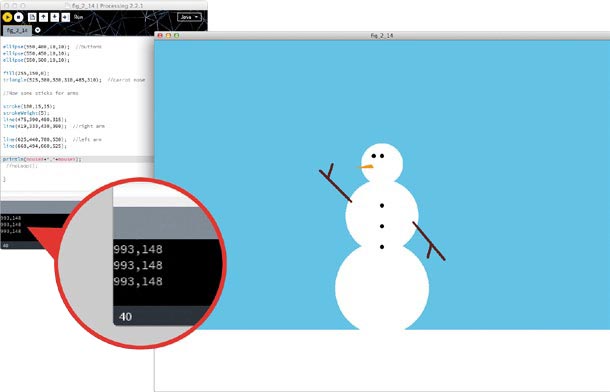
The coordinates of your mouse should print in the console, and as you move your mouse around the sketch window, those numbers should change. So to find the exact values for start points and endpoints of lines and determine where you want to place shapes (such as a button on the snowman), just run this line of code inside the draw() loop and note the coordinates you want to use! This handy piece of code can reduce the amount of trial, error, and frustration for you.
TAKING IT FURTHER
As you draw your own images, look for creative ways to use the different shapes available in Processing. You could use a combination of lines and quadrilaterals to make a snowflake, or perhaps you could use ellipses and rectangles to make a car. Try different modifiers to achieve different effects, and be sure to share your work with your friends!