Chapter 5. Multicast VPN
After exploring Internet Multicast over MPLS, let’s see Multicast VPN (MVPN) over MPLS. The three implemented models in growing scalability order, are:
-
Rosen mLDP, already discussed in Chapter 4 and only implemented in IOS XR. In the terms of Table 4-1, it is S2, A1, C2, E3, T2, Y4.
-
VRF In-Band mLDP, only implemented in IOS XR. In the terms of Table 4-1, this model is S2, A2, C2, E3, T2, Y3. It is nearly identical to the one discussed for Internet Multicast in Chapter 4, but it also encodes VPN-specific information (the RD of the S unicast route) in the LDP opaque value.
-
BGP Multicast VPN, formerly known as Next-Generation MVPN or NG-MVPN. It is implemented by both Junos and IOS XR. In the terms of Table 4-1, this model is S2, A3, C3, [E1, E2, E3], [T0, T1, T2, T3, T4], [Y1, Y2, Y3, Y4]. Not all the combinations make sense and/or are supported, though.
As of this writing, the only interoperable solution is BGP MVPN. Fortunately, it is the most flexible and scalable flavor of them all. Table 4-1 lists the different C-Multicast Architectures: Out-of-band (A3) is more scalable than Hop-by-Hop Inter-PE (A2), which in turn is more scalable than Direct Inter-PE (A1). The only implemented solution that is compatible with the A3 model is precisely BGP MVPN.
MVPN is a multidimensional universe, whose richest galaxy is BGP MVPN. Its Out-of-Band signaling approach, which decouples service from transport, makes BGP MVPN flavors and use cases quite extensive. As a technology it requires more time to fully understand and master than In-Band signaling, but it’s worth the effort.
BGP MVPN architectural and functional aspects are described in RFC 6513 - Multicast in MPLS/BGP IP VPNs. This RFC is the result of a multivendor effort to achieve a common specification for Multicast VPN in the industry. It provides a big framework that supports two totally different C-Multicast signaling paradigms:
-
PE-PE C-PIM peering: Rosen GRE and Rosen mLDP. These models rely on the Direct Inter-PE (A1) architecture and are discussed in Chapter 4.
-
PE-PE BGP peering: BGP MVPN. This model relies on the Out-of-Band (A3) architecture.
Note
In-Band MVPN signaling is not covered in this RFC. Refer back to Chapter 4 for more details on this model, which relies on the Hop-by-Hop Inter-PE (A2) architecture.
BGP Multicast VPN with mLDP Transport
This chapter is based on the same topology as Chapter 4 (see Figure 4-1).
Note
In this chapter, Figure 4-1 needs to be modified so that the righthand AS is 65001, the BRs are replaced with CEs, and the inter-PE links have IS-IS metric 100.
Let’s discuss BGP MVPN in detail. In the terms of Table 4-1, the following scenario is S2, A3, C3, E3, T2, Y3.
MVPN Address Family
The first step when configuring any BGP MVPN flavor is enabling a new BGP address family. Multiprotocol BGP routes can encode virtually anything. Yes, also C-Multicast state: neighbors, joins, prunes and registers. How? With a new Multiprotocol BGP Network Layer Reachability Information (NLRI), called MCAST-VPN. This NLRI is commonly called the MVPN address family (IPv4: AFI=1, SAFI=5; IPv6: AFI=2, SAFI=5), and it supports different route types. These are described in RFC 6514 - BGP Encodings and Procedures for Multicast in MPLS/BGP IP VPNs. The first scenario illustrated in this chapter involves three of these route types. Let’s first look at the full picture, and then we’ll examine each step in detail.
MVPN route types
Table 5-1 can serve as a reference for all the upcoming Layer 3 (L3) MVPN scenarios, here and in subsequent chapters. All of these routes will be fully explained as the scenarios evolve. For the moment, here is a quick acronym list: AD is Autodiscovery, I is Inclusive, S is Selective, and PMSI is Provider Multicast Service Interface.
| Type | Route name | C-PIM analogy | Has C- information? |
|---|---|---|---|
| 1 | Intra-AS I-PMSI AD (a.k.a., Site AD) | Hello Packet | No |
| 2 | Inter-AS I-PMSI AD | Hello Packet | No |
| 3 | S-PMSI AD | N/A | Yes |
| 4 | Leaf AD | N/A | Yes |
| 5 | Source Active AD | Register-Start | Yes |
| 6 | C-Multicast (C-S, C-G) Source Tree Join | (S, G) Join | Yes |
| 7 | C-Multicast (*, C-G) Shared Tree Join | (*, G) Join | Yes |
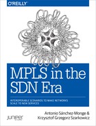
The following pages are dedicated to exploring the signaling in detail. For a first impression, have a look at Figure 5-1, which illustrates how one C-Receiver in one site pulls C-Multicast traffic from a C-Source in a remote site. The lower part of Figure 5-1 shows the signaling of one of the Provider Tunnel branches. You can easily add and merge more branches into the tree by using similar (but not identical) LDP P2MP mechanisms to those discussed in Chapter 4.
Note
You can use the Figure 5-1 as a reference, but don’t worry if it doesn’t make sense yet. As this section progresses, the different pieces will fit together.
The main difference between AD and non-AD routes lies in the Route Target (RT):
-
AD routes have a static configurable RT that is typically imported by all the remote PEs in the MVPN—or, by playing with RT export and import policies, just by a subset of the PEs.
-
Non-AD routes (Types 6 and 7) have a dynamic RT that is imported only by one provider edge (PE): namely, by the sender PE to which the C-Multicast Join is targeted.
Let’s now see a BGP MVPN scenario in detail, step by step.
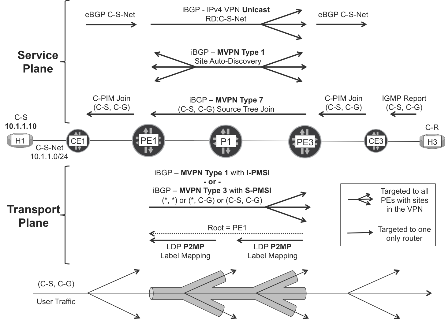
Figure 5-1. BGP Multicast VPN with mLDP transport—the full picture
MVPN address family configuration
First, the PE-RR BGP sessions need to support the new NLRI.
Note
Multicast relies on a healthy unicast service. The configuration examples that follow assume that the IPv4 VPN address family (inet-vpn unicast or vpnv4 unicast) is already configured.
This is the additional configuration in a Junos PE (it would be inet6-mvpn for IPv6):
Example 5-1. MVPN address family configuration—PE1 (Junos)
protocols {
    bgp {
        group iBGP-RR {
            family inet-mvpn signaling;
            mvpn-iana-rt-import;
}}}
Adding this configuration to all of the BGP groups also does the trick on Junos RRs. The mvpn-iana-rt-import command ensures that a very important extended community has the correct format to interoperate with other vendors.
Here is the additional configuration on IOS XR PEs (it would be ipv6 mvpn for IPv6):
Example 5-2. MVPN address family configuration—PE2 (IOS XR)
router bgp 65000
address-family ipv4 mvpn
 !
 neighbor-group RR
  address-family ipv4 mvpn
!
Note
On RRs running IOS XR, you also need to add the route-reflector-client knob under each neighbor[-group] adddress-family.
With this configuration in place, the new address family is successfully negotiated, as shown in Example 5-3. No MVPN routes are exchanged yet, though.
Example 5-3. BGP MVPN address family—PE1 (Junos) and PE2 (IOS XR)
juniper@PE1> show bgp summary instance master
[...]
Peer              AS    State|#Active/Received/Accepted/Damped...
172.16.0.201   65000    Establ
  inet.0: 0/0/0/0
  bgp.l3vpn.0: 12/12/12/0
  bgp.mvpn.0: 0/0/0/0
  VRF-A.inet.0: 12/12/12/0
172.16.0.202   65000    Establ
  inet.0: 0/0/0/0
  bgp.l3vpn.0: 0/12/12/0
  bgp.mvpn.0: 0/0/0/0
  VRF-A.inet.0: 0/12/12/0


RP/0/0/CPU0:PE2#show bgp ipv4 mvpn summary
[...]
Neighbor          AS MsgRcvd MsgSent  InQ OutQ  Up/Down  St/PfxRcd
172.16.0.201   65000       9       7    0    0 00:00:07          0
172.16.0.202   65000      11       7   80    0 00:00:11          0
Configuring BGP MVPN
What is an MVPN? It is not a new type of VPN; rather, it is an extension of a BGP/MPLS IP VPN. The starting point is a classic VRF, with unicast routing up and running. On this very same VRF, you turn on multicast services: this is how you make an MVPN.
Junos basic configuration
The initial VRF-A configuration is similar to the L3VPN baseline of Chapter 3 (Example 3-24, Example 3-28, and Example 3-32). There are minor differences, mainly at the access interface configuration level (VLANs and IPv4 addresses).
The additional configuration at PE1 makes its VRF-A part of a MVPN:
Example 5-4. Multicast VPN configuration at VRF-A—PE1 (Junos)
1     interfaces {
2         vt-2/0/0 unit 101 family inet;
3     }
4     policy-options {
5         policy-statement PL-VRF-A-EXP {
6             # Other terms #
7             term MULTICAST {
8                 from family inet-mvpn;
9                 then {
10                    community add RT-VPN-A;
11                    accept;
12    }}}}
13    routing-instances {
14        VRF-A {
15            interface vt-2/0/0.101 multicast;
16            vrf-table-label;
17            protocols {
18                pim {
19                    interface ge-2/0/1.1010;
20                    interface ge-2/0/2.1011;
21                }
22                mvpn;
23    }}}
Chapter 3 explains the vrf-table-label and vt- concepts. With this configuration, the VRF behaves in vrf-table-label mode for unicast services while it relies on a vt- interface for multicast. Although strictly speaking a vt- interface is not mandatory for Multicast VPN to work, it becomes necessary if a given LSR behaves as a Bud LSR—simultaneously acting as an egress PE and Transit P for a given flow. Because in most topologies PEs can potentially be Bud LSRs, the vt- interface is a de facto requirement for MVPN in Junos. Not a big deal in modern platforms, which implement vt- directly on the Packet Forwarding Engines. Another specific feature that requires vt- interfaces in Junos is MVPN Extranet.
As you can see, the access interfaces and the PIM configuration have simply been moved from the global routing table to the VRF. This makes the VRF exchange Protocol Independent Multicast (PIM) and Internet Group Management Protocol (IGMP) packets with the connected CEs and hosts. Finally, MVPN (line 22) is not really a protocol; it is the “glue” between C-PIM and BGP. With protocols mvpn, the VRF is no longer isolated from the multicast point of view. PEs can become MVPN neighbors of each other and exchange C-Multicast information, all by using BGP.
IOS XR basic configuration
Again, the initial VRF-A configuration presented in the following example builds on top of a L3VPN baseline that is very similar to that of Chapter 3 (Examples Example 3-25 and Example 3-29). There are minor differences, mainly at the access interface configuration level (VLANs and IPv4 addresses). Example 5-5 shows the additional configuration required to make PE4’s VRF-A part of a MVPN.
Note
To bring MVPN neighbors up, IOS XR requires information about P-Tunnels. For this reason, the following example includes references to mLDP P2MP and MDT. Just ignore them for the moment.
Example 5-5. Multicast VPN configuration at VRF-A—PE2 (IOS XR)
1     router bgp 65000
2       vrf VRF-A
3       address-family ipv4 mvpn
4     !
5     multicast-routing
6      address-family ipv4
7       interface Loopback0
8        enable
9       !
10      mdt source Loopback0
11     !
12     vrf VRF-A
13      address-family ipv4
14       interface GigabitEthernet0/0/0/0.1020
15        enable
16       !
17       interface GigabitEthernet0/0/0/1.1022
18        enable
19       !
20       bgp auto-discovery mldp
21       mdt default mldp p2mp
22    !
23    mpls ldp
24     mldp
MVPN Site AD
With the previous configuration, PEs become the following:
-
C-PIM neighbors of the directly connected CEs
-
MVPN neighbors of the remote PEs
Example 5-6. C-PIM and MVPN neighbors—PE1 (Junos)
juniper@PE1> show pim neighbors instance VRF-A

Instance: PIM.VRF-A
Interface         IP V Mode    Option       Uptime Neighbor addr
ge-2/0/1.1010      4 2         HPLGT   1d 01:52:51 10.1.0.0

juniper@PE1> show mvpn neighbor inet instance-name VRF-A

Instance : VRF-A
  MVPN Mode : SPT-ONLY
  Neighbor                          Inclusive Provider Tunnel
  172.16.0.22
  172.16.0.33
  172.16.0.44
How do the PEs become MVPN neighbors of each other in VRF-A? They do it by exchanging a new BGP route. The MCAST-VPN address family defines seven route types. Out of them, Type 1 routes perform Site AD. They are functionally similar to PIM hellos, except that they are only signaled once, not periodically.
The official name of Type 1 routes is Intra-AS I-PMSI AD, because they may carry a BGP attribute called PMSI. This is a mandatory attribute for some route types, but it is totally optional for Type 1. This book sometimes refers to Type 1 routes as Site AD.
MVPN Site AD in PEs running Junos
Following is the Intra-AS Site AD route advertised by PE1 (Junos):
Example 5-7. MVPN Type 1: intra-AS site AD route—PE1 (Junos)
juniper@PE1> show route advertising-protocol bgp 172.16.0.201
             match-prefix "1:*" detail
[...]
bgp.mvpn.0: 6 destinations, 9 routes (6 active, ..., 0 hidden)
* 1:172.16.0.11:101:172.16.0.11/240 (1 entry, 1 announced)
 BGP group iBGP-RR type Internal
     Nexthop: Self
     Flags: Nexthop Change
     Localpref: 100
     AS path: [65000] I
     Communities: target:65000:1001

VRF-A.mvpn.0: 6 destinations, 9 routes (6 active, ..., 0 hidden)
# Same route here – omitted for brevity
The format of the prefix is 1:<RD>:<ADVERTISING_PE_ROUTER_ID>. The /240 mask is internal in Junos and not advertised via iBGP: you can simply ignore it.
As is detailed in Chapter 3, the Route Distinguisher (RD) format can be <ROUTER_ID>:<VPN_ID> or <AS>:<VPN_ID>. In this chapter, the format chosen is <ROUTER_ID>:<VPN_ID>. The MVPN multihoming section explains its advantages.
The route target is 65000:1001, exactly the same as in unicast routes. Consequently, the resulting MVPN topology is a full PE-PE mesh. This is actually chosen by configuration (Example 5-4, line 10), and you can modify it to achieve arbitrary MVPN topologies. This can make sense, for example, if the set of sender PEs is clearly identified and you don’t want the sender PEs to become neighbors of each other. The same logic would apply to receiver PEs. BGP with its flexibility makes that possible. Finally, note that this route doesn’t carry a PMSI attribute (at least yet).
Junos—even on pure PEs with no route reflection enabled—advertises MVPN routes from the bgp.mvpn.0 table. The routes are first copied from VRF-A.mvpn.0 to bgp.mvpn.0, and then advertised to other PEs via iBGP. This implementation is different from unicast IP VPN routes, which are advertised by default from the VRF tables on pure PEs (you can find more details in Chapter 3).
MVPN Site AD in PEs running IOS XR
Here is the Intra-AS Site AD route advertised by PE2 (IOS XR):
Example 5-8. MVPN Type 1: intra-AS site AD route—PE2 (IOS XR)
RP/0/0/CPU0:PE2#show bgp ipv4 mvpn vrf VRF-A advertised

Route Distinguisher: 172.16.0.22:101
[1][172.16.0.22]/40 is advertised to 172.16.0.202
[...]
  Attributes after outbound policy was applied:
    next hop: 172.16.0.22
    ORG AS COMM EXTCOMM
    origin: IGP
    aspath:
    community: no-export
    extended community: RT:65000:1001
[...]
Although the format looks a bit different, Junos and IOS XR advertise the NLRI exactly with the same format on the wire (only the BGP attributes may differ).
Signaling C-Multicast (S, G) Join State with BGP
This example is based on Source-Specific Multicast (SSM) mode. Any Source Multicast (ASM) is covered later.
In SSM mode, the sources are known beforehand, so the forwarding state is created independently of the multicast traffic. If the sources begin to send multicast traffic before there is any receiver, the First Hop Router (FHR)—let it be a PE or a CE—simply drops the traffic. Indeed, in SSM (unlike ASM) the sources play no role in building the multicast tree. The receivers, with their IGMP (S, G) Reports, are the ones that trigger the multicast tree signaling.
Let’s start the following receivers of the (10.1.1.10, 232.1.1.1) flow: H3, H4, H33, H34, and H44 (see Figure 4-1). The C-Multicast source is H1, so PE1 is the sender PE.
Receiver PE configuration
There are two receiver PEs in this example, PE3 and PE4, which run Junos and IOS XR, respectively. They both get IGMP (S, G) Reports from the directly connected hosts (H33, H34, and H44) and C-PIM Joins from their downstream CEs (CE3 and CE4). Any of these messages—IGMP Report or PIM Join—is enough for the receiver PEs to generate a (C-S, C-G) Join state pointing to the upstream C-Source. Let’s see how PE3 and PE4 perform Reverse Path Forwarding (RPF) toward a C-Source that is beyond a remote PE (PE1).
Junos receiver PEs just require the basic MVPN AD configuration (Example 5-4). With it in place, PE3 performs RPF successfully toward the C-Source, as demonstrated here:
Example 5-9. Successful RPF at receiver PE—PE3 (Junos)
juniper@PE3> show pim join inet instance VRF-A
Instance: PIM.VRF-A Family: INET
R = Rendezvous Point Tree, S = Sparse, W = Wildcard

Group: 232.1.1.1
    Source: 10.1.1.10
    Flags: sparse,spt
    Upstream protocol: BGP
    Upstream interface: Through BGP
Then, PE3 converts this downstream Join state into a BGP route. But how can PE3 make sure that the new route is targeted only to PE1, the Source PE? This logic and the format of the new route are unveiled in the next few pages.
Before that, let’s see how PE4 performs RPF toward the remote C-Source. To perform Site Auto-Discovery, IOS XR receiver PEs require P-Tunnel specific information (see Example 5-5, lines 20 and 21).
However, that configuration is still incomplete, so RPF fails:
Example 5-10. Failed RPF at receiver PE—PE4 (IOS XR)
RP/0/0/CPU0:PE4#show mrib vrf VRF-A route 232.1.1.1
[...]
(10.1.1.10,232.1.1.1) RPF nbr: 0.0.0.0 Flags: RPF
  Up: 2d00h
  Outgoing Interface List
    GigabitEthernet0/0/0/2.1034 Flags: LI, Up: 00:05:51
    GigabitEthernet0/0/0/3.1044 Flags: F NS LI, Up: 2d00h
Example 5-11 provides the additional configuration, which will allow IOS XR PE4 to do a successful RPF lookup and signal the C-Multicast Join state via BGP.
Example 5-11. RPF policy at receiver PE—PE4 (IOS XR)
route-policy PL-BGP-MVPN-LDP-P2MP
  set core-tree mldp-default
end-policy
!
router pim
 vrf VRF-A
  address-family ipv4
   rpf topology route-policy PL-BGP-MVPN-LDP-P2MP
   mdt c-multicast-routing bgp
!
After this configuration is applied, PE4 performs a successful RPF lookup:
Example 5-12. Successful RPF at receiver PE—PE4 (IOS XR)
RP/0/0/CPU0:PE4#show mrib vrf VRF-A route 232.1.1.1
[...]
(10.1.1.10,232.1.1.1) RPF nbr: 172.16.0.11 Flags: RPF
  Up: 2d00h
  Incoming Interface List
    LmdtVRF-A Flags: A LMI, Up: 00:00:07
  Outgoing Interface List
    GigabitEthernet0/0/0/2.1034 Flags: LI, Up: 00:00:04
    GigabitEthernet0/0/0/3.1044 Flags: F NS LI, Up: 2d00h
It’s time to see how the BGP Joins are built and targeted.
Route Import—a new extended community
First, let’s have a look at PE1 (the sender PE) and forget for a moment about multicast. PE1 advertises the unicast route toward the source (10.1.1.10):
Example 5-13. Unicast C-S route, advertised from sender PE—PE1 (Junos)
juniper@PE1> show route advertising-protocol bgp 172.16.0.201
             10.1.1.10 detail

VRF-A.inet.0: 22 destinations, 30 routes (22 active, ..., 0 hidden)
* 10.1.1.0/24 (1 entry, 1 announced)
 BGP group iBGP-RR type Internal
     Route Distinguisher: 172.16.0.11:101
     VPN Label: 16
     Nexthop: Self
     Flags: Nexthop Change
     MED: 100
     Localpref: 100
     AS path: [65000] 65001 I
     Communities: target:65000:1001 src-as:65000:0
                  rt-import:172.16.0.11:8
This unicast route has the following communities:
-
RT
65000:1001, the full mesh RT of VPN A, so the unicast route is installed in all the PEs of the VPN. -
Source AS
65000:0, matching the locally configured AS at PE1 and PE3. -
Route Import
172.16.0.11:8. It contains the router ID of PE1 (its global loopback address) and8, a number that is locally generated by PE1.
Note
Chapter 3 discussed the <IP>:<number> format. But that format was associated with RDs, which have nothing to do with communities.
PE1 adds these two new communities (Source AS and Route Import) to the VPN IP unicast routes, simply because MVPN is enabled at VRF-A and all the unicast subnets might potentially contain C-Sources. But what is the purpose of Route Imports? Route Import communities are C-Multicast Join attractors.
Now, if number 8 is locally generated by PE1, it must mean something to PE1.
Example 5-14. Internal policies at sender PE—PE1 (Junos)
juniper@PE1> show policy __vrf-mvpn-export-inet-VRF-A-internal__
Policy __vrf-mvpn-export-inet-VRF-A-internal:
 Term unnamed:
    then community
           + __vrf-mvpn-community-rt_[rt-import:172.16.0.11:8]
           + __vrf-mvpn-community-src_[src-as:65000:0]
         accept

juniper@PE1> show policy __vrf-mvpn-import-cmcast-VRF-A-internal__
Policy __vrf-mvpn-import-cmcast-VRF-A-internal:
 Term unnamed:
    from community
          vrf-mvpn-community-rt_[target:172.16.0.11:8]
    then accept
Nobody configured these policies, at least directly. They were dynamically created after applying the set routing-instances VRF-A protocols mvpn statement. The export-inet policy explains why the unicast routes now carry two additional communities. The import-cmcast policy is even more interesting: if a C-Multicast—whatever that means—BGP route arrives with RT 172.16.0.11:8, it is imported in VRF-A. In other words, number 8 locally represents VRF-A at PE1.
Route Import and RT are symmetrical or reverse concepts:
-
PE1 sets RT
65000:1001, hoping that its prefix will be imported in the VRFs of the remote PEs. RTs are like keys that open others’ homes. -
PE1 sets Route Import
172.16.0.11:8, telling remote PEs what RT value they must set in order for their routes to be imported in PE1’s local VRF. Sending a Route Import is like telling your friend a code to enter your own home.
So, if a PE adds a Route Import community to a prefix, it is basically instructing the remote PEs to put this value in your prefixes’ RT, and they will be installed on my VRF.
Stripping extended communities from PE→CE eBGP updates
It is a good practice to keep extended communities internal to the local AS. To achieve that, you can remove them with eBGP export policies, as illustrated here:
Example 5-15. Stripping extended communities—PE3 (Junos)
policy-options {
    policy-statement PL-VRF-A-eBGP-65001-OUT {
        term BGP {
            from protocol bgp;
            then {
                community delete RT-ALL;
                community delete RI-ALL;
                community delete SRC-AS-ALL;
            }
        } # Other terms omitted
    }
    community RT-ALL members target:*:*;
    community RI-ALL members rt-import:*:*;
    community SRC-AS-ALL members src-as:*:*;
}
As discussed earlier in Chapter 3, IOS XR does not require this explicit configuration.
MVPN Source Tree Join routes
OK, let’s get back to multicast. PE3 converts its downstream C-PIM Join state into a BGP route called (C-S, C-G) Source Tree Join. This is the Type 7 route of the MCAST-VPN NLRI, and it is the BGP equivalent of a (C-S, C-G) PIM Join; see Example 5-16.
Example 5-16. Type 7—(C-S, C-G) Source-Tree Join—PE3 (Junos)
juniper@PE3> show route advertising-protocol bgp 172.16.0.201
             match-prefix "7:*" detail
[...]
bgp.mvpn.0: 7 destinations, 10 routes (7 active, ..., 0 hidden)
* 7:172.16.0.11:101:65000:32:10.1.1.10:32:232.1.1.1/240
 BGP group iBGP-RR type Internal
     Nexthop: Self
     Flags: Nexthop Change
     Localpref: 100
     AS path: [65000] I
     Communities: target:172.16.0.11:8

VRF-A.mvpn.0: 7 destinations, 10 routes (7 active, ..., 0 hidden)
# Same route here – omitted for brevity
The format of a Type 7 route is 7:<ROOT_RD>:<AS>:<C-S_LENGTH>:<C-S_ADDRESS>:<C-G_LENGTH>:<C_G_GROUP>. The <ROOT_RD> field is the RD of VRF-A at the Root PE (PE1).
The prefix does not contain any information about the receiver PE addresses. Imagine 100 receiver PEs have downstream subscribers for the (10.1.1.10, 232.1.1.1) flow. In this case, the RR gets 100 identical (C-S, C-G) Source Tree Join prefixes, one from each receiver PE. Then, the RR selects one of the 100 routes and reflects it. This is totally fine, because at this C-Multicast stage the sender PE only needs to know whether it needs to add the core to the outgoing interface list; in other words, whether there are receiver PEs for the flow. As for the number and identity of the receiver PEs, it simply does not matter from the perspective of C-Multicast. It is definitely relevant later, when the P-Tunnel is selected and signaled, but that takes place in the Provider context and the sender PE finds the information elsewhere, not in the Source Tree Join routes.
The meat is in the RT—target:172.16.0.11:8—which identifies the Source PE at which the BGP route is targeted. Functionally, this RT is equivalent to the Upstream Neighbor field of a PIM Join packet. So, the route is targeted to PE1 (172.16.0.11), the sender PE. But what does number 8 stand for? If you go back to Example 5-13, you can see that 172.16.0.11:8 is precisely the Route Import carried in the unicast route toward the C-Source. Figure 5-2 illustrates this mechanism.

Figure 5-2. C-Multicast Source Tree Join and Route Import
It all comes from the RPF lookup at PE3, the receiver PE. The unicast route toward the C-Source has Route Import 172.16.0.11:8, and this value is literally copied into the RT of PE3’s Source Tree Join BGP route. In this way, PE3 targets the (C-S, C-G) BGP Join to PE1, its RPF upstream PE. This route is only imported in PE1’s VRF-A.
Receiver PE4, which runs IOS XR, also generates a (C-S, C-G) Source Tree Join route:
Example 5-17. Type 7—(C-S, C-G) Source-Tree Join—PE4 (IOS XR)
RP/0/0/CPU0:PE4#show bgp ipv4 mvpn advertised
[...]
Route Distinguisher: 172.16.0.44:101  /* This is the local RD */
[7][172.16.0.11:101][65000][32][10.1.1.10][32][232.1.1.1]/184
[...]
  Attributes after outbound policy was applied:
    next hop: 172.16.0.44
    ORG AS EXTCOMM
    origin: IGP
    aspath:
    extended community: RT:172.16.0.11:8
As you can see, the NLRI in Example 5-16 and Example 5-17 are identical. Indeed, the NLRI does not contain information of the receiver PE.
Let’s get back to the (10.1.1.10, 232.1.1.1) flow. At this point, the Root PE (PE1) still doesn’t forward the C-Multicast traffic into any P-Tunnel; see Example 5-18.
Example 5-18. Discarding C-Multicast traffic at ingress PE—PE1 (Junos)
juniper@PE1> show route forwarding-table multicast table VRF-A detail
[...]
Destination        Type RtRef Next hop   Type Index    NhRef Netif
232.1.1.1.10.1.1.10/64
                   user     0            mdsc    28170     3
The mdsc next hop stands for multicast discard.
Why is the traffic discarded? Simply, there is no P-Tunnel yet. Let’s take care of that.
Signaling Provider Tunnels—BGP and the PMSI Attribute
Let’s move from the customer (C-) to the provider (P-) context.
Provider tunnels and PMSIs
RFC 6513 classifies the PEs depending on their role in each Multicast VPN:
- Sender Sites set
- PEs in the Sender Sites set can send C-Multicast traffic to other PEs by using P-Tunnels. (In this book, we use the terms “sender PE”, “ingress PE,” and “root PE” interchangeably.)
- Receiver Sites set
- PEs in the Receiver Sites set can receive C-Multicast traffic from P-Tunnels rooted on other (sender) PEs. (In this book, we use the terms “receiver PE,” “egress PE,” and “leaf PE” interchangeably.)
One PE can be both sender and receiver in the same VPN. Every time you read the words “sender,” “receiver,” “ingress,” “egress,” “root,” or “leaf”, keep in mind that they are used in the context of one specific VPN and even one C-Multicast flow. It is perfectly possible for one PE to be sender for VPN A, receiver for VPN B, and both sender and receiver for VPN C.
RFC 6513 also defines the general concept of PMSI (P-Multicast Service Interface) as the virtual interface that a sender PE uses to put C-Multicast traffic into a P-Tunnel. The P-Tunnel is functionally point-to-multipoint (even if it might be implemented differently) and takes the traffic to a set of receiver PEs. It is very common to refer to the P-Tunnel as a tree, where the sender PE is the root and the receiver PEs are the leaves. The P-Tunnel provides an overlay to the C-Multicast tree: from the point of view of the C-Multicast tree, the P-Tunnel is just one hop.
There are basically three criteria to classify P-Tunnels:
-
Whether the P-Tunnel can be shared by different VPNs: Aggregate and Non-Aggregate, respectively.
-
How the P-Tunnel’s leaf set is chosen: Inclusive or Selective.
-
The underlying tunnel technology: Ingress Replication, RSVP-TE P2MP, LDP P2MP, LDP MP2MP, and multipoint GRE.
For the first classification, let’s consider two VRFs (A and B) and one P-Tunnel. Typically, the P-Tunnel is dedicated to one VPN only; either VRF A or B can use it, but not both. There are two exceptions to this rule:
-
In current vendor implementations, two VPNs can share a given P-Tunnel only if they leak unicast prefixes with each other. In other words, two VPNs that are isolated from each other cannot share a P-Tunnel.
-
RFC 6513 also defines the concept of an Aggregate Tunnel, where MPLS label stacking allows two distinct (isolated from each other) VRFs to use the same P-Tunnel. As of this writing, neither Junos nor IOS XR implements Aggregate Tunnels.
In current vendor implementations, and therefore in all of this book’s examples, there is a 1:1 relationship between each PMSI and each P-Tunnel. In other words, only one PMSI can point to a given Non-Aggregate P-Tunnel.
Provider tunnel classification—based on the leaf set
In Figure 5-3, PE1 is the sender PE of C-Multicast flow (S1, G1) and it has four MVPN neighbors in VRF-A: PE2, PE3, PE4, and PE5. Clearly, PE2 has a high likelihood to be a receiver PE because it has downstream receivers precisely for (S1, G1). But, what about the other PEs? It depends on the P-Tunnel type:
-
An Inclusive Tree (P-Tunnel) goes from the sender PE to all of its MVPN neighbors, regardless of their C-PIM Join state. In this example, only PE2 has downstream receivers for (S1, G1). As for the other PEs, they simply drop the packets locally, unless the topology makes them act as transit LSRs for other downstream PEs.
-
Selective Trees only reach the receiver PEs with downstream C-Multicast receivers. C-Multicast flows are mapped to Selective PMSIs (S-PMSIs) in different manners. Out of the three S-PMSI examples in Figure 5-3, the first two of them are of type wildcard: (*, *) S-PMSI points to a tree that reaches all of the PEs with downstream receivers for any flow; (*, G1) S-PMSI points to the PEs with downstream receivers for any (S, G1) flow, where S may be equal to or different from S1. Finally, the (S1, G1) S-PMSI points to the PEs with downstream receivers for (S1, G1).
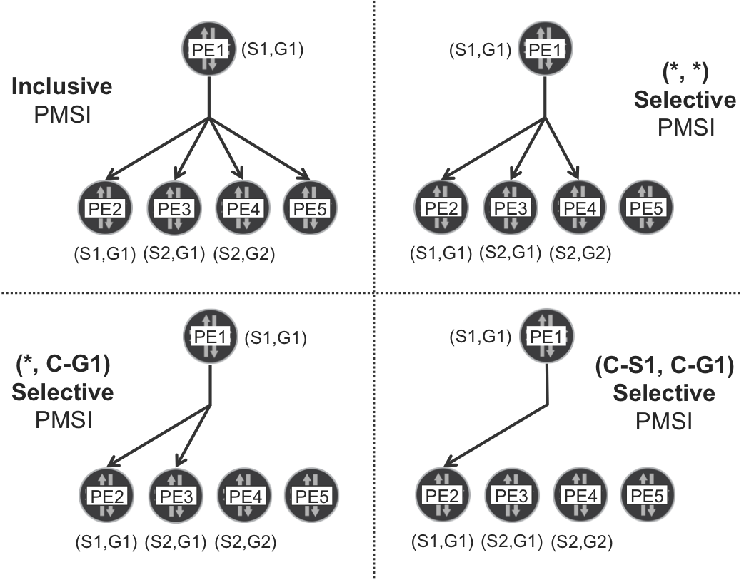
Figure 5-3. Four types of single-rooted provider tunnels
Note
In a unicast analogy, you can see PMSIs as if they were routes. An Inclusive PMSI (I-PMSI) is like a static default route; (*, *) S-PMSI is like a dynamic default route; (*, G1) S-PMSI is like a more specific route; and (S1, G1) S-PMSI is like a host /32 route.
It is important to note that the appearance of wildcards does not mean that the scenario moved into ASM mode. Indeed, wildcard S-PMSIs are just a method to map C-Multicast flows to P-Tunnels. This concept is orthogonal to C-PIM SSM versus ASM: the model used in the core might or might not match the C-Multicast flavor.
In BGP MVPN, Inclusive Tunnels are advertised inside Type 1 (Intra-AS I-PMSI AD) routes, by using their optional PMSI attribute. As for Selective Tunnels, they are advertised inside the mandatory PMSI attribute of the MCAST-VPN route Type 3: Selective PMSI Auto-Discovery (S-PMSI AD).
In the multicast world, it is not possible to achieve bandwidth efficiency and signaling efficiency at the same time; it is one or the other. (S, G) and (*, G) Selective Tunnels are the most efficient in terms of bandwidth, at the expense of a higher load on the control plane. Inclusive Tunnels and (*, *) Selective Tunnels, on the other hand, have a very efficient signaling, but they often result in a waste of bandwidth resources.
Tip
For a good compromise between bandwidth and signaling efficiency, it is a good practice to set a data threshold for the signaling of Selective Tunnels. In this way, low-bitrate flows stay in Inclusive Tunnels, whereas high-bitrate flows are transported in Selective Tunnels.
Inclusive PMSI
Junos MVPN PEs are by default pure receiver PEs. They need explicit P-Tunnel configuration to act as sender PEs. In the following example, PE1 becomes—in the context of VRF-A—the root of an Inclusive P-Tunnel that is to be signaled with mLDP P2MP:
Example 5-19. Inclusive Tunnel based on mLDP P2MP—PE1 (Junos)
routing-instances {
    VRF-A {
        provider-tunnel ldp-p2mp;
}}
Now, at this point, PE1 readvertises its Type 1 route (now, properly called I-PMSI AD) with a new attribute called PMSI:
Example 5-20. Type 1 route with mLDP P2MP I-PMSI—PE1 (Junos)
juniper@PE1> show route advertising-protocol bgp 172.16.0.201
             match-prefix "1:*" detail
[...]
bgp.mvpn.0: 7 destinations, 11 routes (7 active, ..., 0 hidden)
* 1:172.16.0.11:101:172.16.0.11/240 (1 entry, 1 announced)
[...]
     Communities: target:65000:1001
     PMSI: Flags 0x0: Label 0: LDP-P2MP: Root 172.16.0.11, lsp-id 16777226

VRF-A.mvpn.0: 7 destinations, 11 routes (7 active, ..., 0 hidden)
# Same route here – omitted
Thanks to the PMSI attribute, PE1 tells all its MVPN neighbors about the new P-Tunnel: it is based on LDP P2MP, the root is PE1 itself, and there is an opaque value (displayed as lsp-id). These are mLDP root and opaque values, two concepts that were previously explained in the context of mLDP Inband Signaling. Now, in the BGP MVPN case, the mLDP opaque value no longer contains C-Multicast information; it is simply a number, locally significant to PE1, which is the root PE that advertises the PMSI.
Are you wondering about the label field? It is mandatory in the PMSI attribute, and it is zero in this case because the sender PE does not choose the label value.
Let’s focus on PE2, a sender PE running IOS XR. Site Auto-Discovery in IOS XR—unlike in Junos—requires some P-Tunnel configuration to take place. In other words, an auto-discoverable MVPN PE running IOS XR can potentially be a sender PE by default. Let’s pick the key lines from Example 5-5, in the context of the Inclusive P-Tunnel that is rooted at PE2 and bound to VRF-A.
Example 5-21. Inclusive Tunnel based on mLDP P2MP—PE2 (IOS XR)
multicast-routing
 vrf VRF-A
  address-family ipv4
   bgp auto-discovery mldp
   mdt default mldp p2mp
!
With this configuration, PE2 sends the MCAST-VPN Type 1—Intra-AS I-PMSI—route with the PMSI attribute, as you can see from the perspective of the Junos RR.
Example 5-22. Type 1 route with mLDP P2MP I-PMSI—PE2 (IOS XR)
juniper@RR1> show route receive-protocol bgp 172.16.0.22
             match-prefix "1:*" detail table bgp.mvpn
[...]
* 1:172.16.0.22:101:172.16.0.22/240 (1 entry, 1 announced)
[...]
   Communities: no-export target:65000:1001
   PMSI: Flags 0x0: Label 0: LDP-P2MP: Root 172.16.0.22, lsp-id 2
Note
It is possible to remove the PMSI attribute from the Type 1 route by using multicast-routing vrf VRF-A address-family ipv4 bgp auto-discovery mldp receiver-site.
Before moving on to how the actual mLDP tunnel is built, let’s explore a bit more about the PMSI attribute’s signaling with BGP, this time in the context of Selective Tunnels.
(S, G) Selective PMSI
With the configuration shown in Example 5-23, the Junos sender PE (PE1) creates a specific (S, G) S-PMSI that points to a Selective P-Tunnel, also built with mLDP P2MP.
Example 5-23. (C-S, C-G) S-PMSI based on mLDP P2MP—PE1 (Junos)
routing-instances {
    VRF-A {
        provider-tunnel {
            selective {
                group 232.0.0.0/8 {
                    source 0.0.0.0/0 {
                        ldp-p2mp;
                        threshold-rate <kbps>;  # Optional
}}}}}}
The (10.1.1.10, 232.1.1.1) Source Tree Join BGP route—sent by remote PEs and targeted to PE1—matches the rule (S, G) = (0/0, 232/8), so PE1 does the following:
-
If there is no
threshold-rate, or if the (C-S, C-G) bit rate exceeds the configured value, PE1 advertises a (C-S, C-G) S-PMSI AD route. Later, PE1 switches this flow’s C-Multicast packets to the new (C-S, C-G) Selective Tunnel. -
If there is a
threshold-rate, but the actual (C-S, C-G) bit rate is below the configured value, PE1 does not advertise any (C-S, C-G) S-PMSI AD route. And if it had previously advertised one such route, PE1 withdraws it. Then, PE1 switches this flow’s C-Multicast packets into the Inclusive Tunnel, if any. This switchover can be further tuned with timers.
Warning
If you specify a threshold-rate and there is no Inclusive PMSI, PE1 cannot forward the low-bitrate flows and discards the packets. For this reason, it is essential to configure an Inclusive PMSI as a fallback whenever a flow does not reach the configured threshold-rate.
Example 5-24 shows the newly generated (S, G) S-PMSI MVPN Type 3 route.
Example 5-24. Type 3—(C-S, C-G) S-PMSI AD route—PE1 (Junos)
juniper@PE1> show route advertising-protocol bgp 172.16.0.201
             match-prefix "3:*" detail
[...]
bgp.mvpn.0: 8 destinations, 12 routes (8 active, ..., 0 hidden)
* 3:172.16.0.11:101:32:10.1.1.10:32:232.1.1.1:172.16.0.11/240
 BGP group iBGP-RR type Internal
     Nexthop: Self
     Flags: Nexthop Change
     Localpref: 100
     AS path: [65000] I
     Communities: target:65000:1001
     PMSI: Flags 0x0: Label 0: LDP-P2MP: Root 172.16.0.11 ,
                               lsp-id 17004996

VRF-A.mvpn.0: 8 destinations, 12 routes (8 active, ..., 0 hidden)
# Same route here – omitted
The format of this (S, G) S-PMSI AD route is 3:<ROOT_RD>:<C-S_LENGTH>:<C-S_ADDRESS>:<C-G_LENGTH>:<C_G_GROUP>:<SENDER_PE_ROUTER_ID>. The prefix contains a mix of C-Multicast and Provider information.
Note that the IPv4 address length can either be 0 (for wildcard) or 32 (for specific). In other words, there is no subnetting concept here.
Now, let’s consider the flow (10.1.2.20, 232.1.1.1), whose sender PE is PE2 and it runs IOS XR. Here again, the receivers are: H3, H4, H33, H34, and H44.
Following is the IOS XR configuration required to signal (S, G) Selective PMSIs:
Example 5-25. (C-S, C-G) S-PMSI based on mLDP P2MP—PE2 (IOS XR)
multicast-routing
 vrf VRF-A address-family ipv4
   mdt data mldp <max-number-of-tunnels> threshold <kbps>
!
The threshold is 1 kbps by default, and you can configure immediate-switch if you do not want to set a threshold at all. The latter is the IOS XR’s equivalent to not configuring any threshold-rate in Junos.
Like in Junos, in IOS XR the (C-S, C-G) flow uses the Inclusive Tunnel until it exceeds the bitrate threshold. Then, PE2 advertises a (C-S, C-G) S-PMSI and switches the traffic to the new (C-S, C-G) Selective Tunnel.
Example 5-26. Type 3—(C-S, C-G) S-PMSI AD route—PE2 (IOS XR)
juniper@RR1> show route receive-protocol bgp 172.16.0.22
             match-prefix "3:*" detail table bgp.mvpn
[...]
* 3:172.16.0.22:101:32:10.1.2.20:32:232.1.1.1:172.16.0.22/240
[...]
   Communities: no-export target:65000:1001
   PMSI: Flags 0x0: Label 0: LDP-P2MP: Root 172.16.0.22 , lsp-id 3
Junos and IOS XR behave in the same manner for (S, G) S-PMSI AD routes: they both require a matching (S, G) Source Tree Join targeted at the local PE.
Signaling Provider Tunnels—Multipoint LDP for Transport
Inclusive and Selective Tunnels differ in the way they are signaled in BGP—Type 1 versus Type 3 routes—and, of course, in the leaf set. Let’s focus on the (C-S, C-G) = (10.1.1.10, 232.1.1.1) C-Multicast flow, whose sender PE is PE1. Suppose that PE1 is the root of an Inclusive Tunnel and of a (C-S, C-G) Selective Tunnel:
-
The Inclusive Tree has leaves PE2, PE3, and PE4. This matches the list of PE1’s MVPN neighbors.
-
The (C-S, C-G) Selective Tree has leaves PE3 and PE4. This is indeed the list of PEs with downstream receivers for (C-S, C-G).
When it receives an I-PMSI AD route, a receiver PE looks for a PMSI attribute. If it finds one—remember it is optional—and its type is LDP P2MP, the receiver PE immediately begins to signal an LSP branch toward the root. This happens regardless of the actual C-Multicast state. In the context of a given VRF, a receiver PE must become a leaf of all the I-PMSI’s rooted at its MVPN neighbors, even if the receiver PE is not connected to any C-Multicast receivers whatsoever.
The logic is different for Selective Trees. After receiving an S-PMSI AD route, the receiver PE looks at the PMSI attribute. Then, it checks if there are downstream C-Multicast receivers in the VRF matching the (C-S, C-G) or (*, C-G) or (*, *) information encoded in the NLRI. Only if there is a best-match—in the sense that there is no other NLRI that matches the downstream C-Multicast state in a more specific manner—the receiver PE becomes a leaf of the Selective Tree.
These are the differences. But what do Inclusive and Selective P-Tunnels have in common? If the P-Tunnels are based on LDP P2MP, their Multipoint LDP (mLDP) signaling logic is identical. Although each PMSI has a different [root address, opaque value] pair and it has a different leaf set, there is no clue inside the mLDP FECs about the Inclusive or Selective nature of the tree. Let’s pick as an example a Selective Tree rooted at PE1 and dedicated to the (10.1.1.10, 232.1.1.1) flow. You can compare Figure 5-4 to Example 5-24 and verify that the BGP PMSI attribute matches the mLDP P2MP FEC value.
Figure 5-4. MVPN Selective P-Tunnel—signaled with mLDP P2MP
mLDP signaling begins at the receiver PEs
Remember, in the LDP world, signaling typically begins from the tail end. The following example demonstrates how Junos receiver PE3 proclaims itself a leaf of the new LDP P2MP, and it informs P1 (its RPF neighbor toward the root):
Example 5-27. mLDP P2MP FEC signaling from egress PE—PE3 (Junos)
juniper@PE3> show ldp database p2mp
Input label database, 172.16.0.33:0--172.16.0.1:0
Labels received: 8

Output label database, 172.16.0.33:0--172.16.0.1:0
Labels advertised: 16
  Label     Prefix
 417731      P2MP root-addr 172.16.0.11, lsp-id 17004996 [...]
[...]
In parallel, IOS XR PE4 also informs P2 (its RPF neighbor toward the root) that it intends to become a leaf of the new LDP P2MP tunnel, as shown here in Example 5-28.
Example 5-28. mLDP P2MP FEC signaling from egress PE—PE4 (IOS XR)
RP/0/0/CPU0:PE4# show mpls mldp database root 172.16.0.11
mLDP database
LSM-ID: 0x00015   Type: P2MP   Uptime: 01:53:57
  FEC Root           : 172.16.0.11
  Opaque decoded     : [global-id 17004996]
  Upstream neighbor(s) :
    172.16.0.2:0 [Active] Uptime: 01:53:57
      Local Label (D) : 24026
  Downstream  client(s):
    PIM MDT            Uptime: 01:53:57
      Egress intf     : LmdtVRF-A [...]
There are two things in common between Example 5-27 and Example 5-28: the root 172.16.0.11, and the opaque value 17004996. These are identical to the values encoded in the S-PMSI AD route’s PMSI attribute back in Example 5-24. The label may differ between PE3 and PE4, though: MPLS business as usual.
mLDP signaling continues at the Transit Ps
To review the LDP P2MP signaling and forwarding in detail, refer back to “In-Band Signaling”. The mechanics are almost identical here, except for one difference. In the BGP MVPN service, the mLDP Opaque field no longer contains C-Multicast information; instead, it is just a number, which is locally significant to PE1 because PE1 previously encoded it inside the PMSI attribute.
As the LDP P2MP FEC signaling progresses toward the root, the (root, opaque) values remain unchanged. P2 generates another LDP P2MP label mapping that it sends to P1 the branch point of the LSP. And P1 sends a single Label Mapping to PE1.
Following is the view from P1’s perspective:
Example 5-29. mLDP P2MP FEC signaling at Transit P—P1 (Junos)
juniper@P1> show ldp database p2mp
Input label database, 172.16.0.1:0--172.16.0.2:0
  Label     Prefix
  24001      P2MP root-addr 172.16.0.11, lsp-id 17004996

Output label database, 172.16.0.1:0--172.16.0.2:0

Input label database, 172.16.0.1:0--172.16.0.11:0

Output label database, 172.16.0.1:0--172.16.0.11:0
Label     Prefix
 391728      P2MP root-addr 172.16.0.11, lsp-id 17004996

Input label database, 172.16.0.1:0--172.16.0.33:0
  Label     Prefix
 417731      P2MP root-addr 172.16.0.11, lsp-id 17004996

Output label database, 172.16.0.1:0--172.16.0.33:0
mLDP signaling arrives at the sender PE
When PE1 receives the label mapping from P1, the opaque value 17004996 makes full sense. Indeed, as you can see back in Example 5-24, PE1 had generated that number dynamically! As shown in Example 5-30, there is a useful command that binds C-Multicast state to P-Tunnels.
Example 5-30. C-Multicast state at ingress PE—PE1 (Junos)
juniper@PE1> show mvpn c-multicast inet instance-name VRF-A
[...]
Instance : VRF-A
  MVPN Mode : RPT-SPT
  C-mcast IPv4 (S:G)           Provider Tunnel                           St
  10.1.1.10/32:232.1.1.1/32    S-LDP-P2MP:172.16.0.11, lsp-id 17004996   RM
The RM flag means that the original Source Tree Join was received from a remote PE (as compared to being generated by the local PE). Remember, while keeping in mind Figure 5-1: a Source Tree Join triggered the S-PMSI AD route, which in turn triggered the mLDP signaling from the leaves.
Note
All the signaling described so far is fully driven by the control plane (except when S-PMSI data thresholds are in place). This is one key advantage of BGP MVPN over establishing C-PIM PE-PE adjacencies.
Forwarding plane: from the Junos root PE to the leaves
After the P2MP LSP is completely signaled, the C-Multicast traffic flows nicely to all the receivers. Here is the forwarding state at the sender PE:
Example 5-31. Forwarding state at ingress PE—PE1 (Junos)
juniper@PE1> show route table VRF-A.inet.1 active-path
             match-prefix "232.1.1.1,*"

VRF-A.inet.1: 4 destinations, 5 routes (4 active, ..., 0 hidden)
+ = Active Route, - = Last Active, * = Both

232.1.1.1,10.1.1.10/64*[MVPN/70] 00:10:00
                    > to 10.0.0.3 via ge-2/0/4.0, Push 391728
Note
In both Junos and IOS XR, when any service uses a P2MP LSP for the transport of C-Multicast packets, the ingress PE only pushes one MPLS label. There is no label stacking because the P2MP LSP only transports packets of a single VPN (if the tunnel is non-aggregate). In other words, the P2MP LSP label has a combined service + transport significance.
The forwarding state in the transit LSRs is very similar to the one already shown for mLDP In-Band Signaling, so it is omitted.
Let’s have a look at PE3, a Junos receiver PE (see Example 5-32).
Example 5-32. Forwarding state at an egress PE—PE3 (Junos)
juniper@PE3> show route label 417731

mpls.0: 16 destinations, 16 routes (16 active, 0 holddown, 0 hidden)
+ = Active Route, - = Last Active, * = Both

417731             *[LDP/9] 00:03:47, metric 1
                    > via vt-2/0/0.101, Pop
The C-Multicast packets get their MPLS header removed at the vt- interface. Then, PE3 performs an IPv4 lookup in the context of VRF-A and replicates the packet toward the two access interfaces with downstream receivers.
Likewise, the IOS XR receiver PE4 also pops the label and processes the packet in the context of VRF-A, as illustrated in Example 5-33.
Example 5-33. Forwarding state at egress PE—PE4 (IOS XR)
RP/0/0/CPU0:PE4#show mpls mldp forwarding label 24026
mLDP MPLS forwarding database

24026  LSM-ID: 0x00023 HLI: 0x00001 flags: None
   LmdtVRF-A, RPF-ID: 3, TIDv4: E0000011, TIDv6: E0800011
In this book’s tests, H44 only receives the C-Multicast flow if PE4’s unicast CEF entry for 172.16.0.11 resolves to a LDP label. If it resolves to a RSVP tunnel, the traffic is not forwarded to H44. This restriction was not observed in Junos PE3. Chapter 4 covers this topic in more detail.
Note
Remember that there is no Penultimate Hop Popping (PHP) for P2MP LSPs! There is one MPLS label, end to end. Thanks to this label, receiver PEs know to which VRF the C-Multicast packets belong.
Root PE running IOS XR
Let’s focus for a moment on the (10.1.2.20, 232.1.1.1) flow, whose sender PE is PE2. The lsp-id in Example 5-26 corresponds to the Opaque value locally assigned by PE2.
Example 5-34. mLDP P2MP FEC at the ingress PE—PE2 (IOS XR)
RP/0/0/CPU0:PE2#show mpls mldp database root 172.16.0.22
mLDP database
LSM-ID: 0x0002E   Type: P2MP   Uptime: 1w1d
  FEC Root           : 172.16.0.22 (we are the root)
  Opaque decoded     : [global-id 3]
  Upstream neighbor(s) :
    None
  Downstream  client(s):
    LDP 172.16.0.2:0   Uptime: 23:05:14
      Next Hop         : 10.0.0.5
      Interface        : GigabitEthernet0/0/0/3
      Remote label (D) : 24002
    PIM MDT            Uptime: 1w1d
      Egress intf     : LmdtVRF-A
[...]
By combining the two commands in Example 5-35, you can see how PE2 forwards the (10.1.2.20, 232.1.1.1) packets in the context of VRF-A.
Example 5-35. Forwarding state at ingress PE—PE2 (IOS XR)
RP/0/0/CPU0:PE2#show mrib vrf VRF-A route 232.1.1.1 10.1.2.20 detail
[...]
(10.1.2.20,232.1.1.1) Ver: 0x4313 RPF nbr: 10.1.22.0 Flags: RPF EID
[...]
  Incoming Interface List
    GigabitEthernet0/0/0/0 Flags: A, Up: 01:05:50
  Outgoing Interface List
    LmdtVRF-A Flags: F LMI, Up: 01:05:50, Head LSM-ID: 0x0002E
 [...]

RP/0/0/CPU0:PE2# show mrib mpls forwarding
LSP information (MLDP) :
    LSM ID: 0x0002E Role: Head [...]
    HEAD LSM ID: 0x0002E
[...]
      Outsegment Info #1 [H/Push]:
        Outgoing Label: 24002
        Outgoing  IF: GigabitEthernet0/0/0/3 (P) Nexthop: 10.0.0.5
The key is to link the LSM ID of both commands’ output (LSM stands for Label-Switched Multicast). This method applies to Multicast MPLS in general and is not specific of mLDP.
BGP Multicast VPN with RSVP-TE P2MP Transport
The main advantage of BGP Multicast VPN is the way it decouples C-Multicast from P-Tunnel signaling. The very flexible PMSI attribute is the glue between both worlds. So far, you saw PMSIs encoding LDP P2MP information, but many other P-Tunnel technologies are available. Keep in mind that the sender PE is the one responsible for choosing the P-Tunnel. And each sender PE makes its own choice, which may be even different for each C-Multicast flow. It is up to the receiver PEs to tune and join the P-Tunnels signaled by the sender PEs. This flexible logic is allowed by the protocol and currently implemented by Junos.
Note
In both Junos and IOS XR, it is possible to transport C-Unicast traffic on LDP P2MP LSPs while C-Multicast traffic travels on RSVP-TE P2MP LSPs. The reverse combination (C-Unicast with RSVP-TE P2MP, and C-Multicast with mLDP) is also supported in Junos. The P-Tunnel choices for C-Unicast and C-Multicast are generally independent from each other.
In the interest of brevity, this section skips the Site AD and C-Multicast signaling, which is orthogonal to the P-Tunnel flavor chosen. The goal is to illustrate how you can signal P2MP LSPs by using RSVP-TE and the role that BGP takes on it. You can already guess that the PMSI attribute is of fundamental importance.
In the terms of Table 4-1, the following scenario is S2, A3, C3, E3, T3, Y3.
The baseline RSVP-TE configuration is very simple:
-
Junos PEs and Ps have core links configured under
[edit protocols rsvp]. -
IOS XR PEs and Ps have core links configured under
mpls traffic-eng(and optionallyrsvp).
Advertising the Inclusive PMSI—RSVP-TE P2MP
Sender PE running Junos
PE1 can be the root of only one Inclusive P-Tunnel at VRF-A. If instead of using mLDP (Example 5-19) you choose to build the P-Tunnel with RSVP-TE P2MP, the following example shows you how to do it:
Example 5-36. Inclusive Tunnel based on RSVP-TE P2MP—PE1 (Junos)
routing-instances {
    VRF-A {
        provider-tunnel {
            rsvp-te {
                label-switched-path-template {
                    default-template;
}}}}}
The default-template exists by default, and it means no Traffic Engineering (TE) constraints. It is also possible to explicitly configure named templates that define the TE constraints of the new LSPs. This is indeed one of the unique advantages of RSVP-TE, and it applies to P2MP LSPs, as well. With the previous configuration, PE1 readvertises the Type 1 (I-PMSI AD) BGP route with a new PMSI value.
Example 5-37. Type 1 route with RSVP-TE P2MP I-PMSI—PE1 (Junos)
juniper@PE1> show route advertising-protocol bgp 172.16.0.201
             match-prefix "1:*" detail
[...]
* 1:172.16.0.11:101:172.16.0.11/240 (1 entry, 1 announced)
[...]
     Communities: target:65000:1001
     PMSI: Flags 0x0: Label 0: RSVP-TE: Session_13[172.16.0.11:0:19208:172.16.0.11]
[...]
The PMSI format is already familiar: a protocol (RSVP-TE), a root (172.16.0.11 = PE1), and a number that is locally significant to the root. If you are thinking that this number will be present in RSVP-TE protocol messages, you made a good guess! Indeed, it’s the RSVP-TE Tunnel ID.
The RSVP-TE messages used to establish a P2MP LSP contain an object called P2MP LSP Tunnel IPv4 Session. This object is defined in RFC 4875 - Extensions to RSVP-TE for Point-to-Multipoint TE Label Switched Paths (LSPs). Its format is <Extended Tunnel ID, Reserved, Tunnel ID, P2MP ID> and must be globally unique. And, it is globally unique because it contains the loopback address for PE1 and a number that is locally generated by PE1 in order to identify the P-Tunnel.
Sender PE running IOS XR
PE2 can be the root of only one Inclusive P-Tunnel at VRF-A, right now configured with mLDP (Example 5-21). Example 5-38 contains the syntax to make it based on RSVP-TE P2MP instead.
Example 5-38. Inclusive Tunnel based on RSVP-TE P2MP—PE1 (Junos)
ipv4 unnumbered mpls traffic-eng Loopback0
!
multicast-routing
 vrf VRF-A
  address-family ipv4
   bgp auto-discovery p2mp-te
   mdt default p2mp-te
!
mpls traffic-eng
 auto-tunnel p2mp
  tunnel-id min 1000 max 1050
!
PE2 now sends the MCAST-VPN Type 1—Intra-AS I-PMSI—route with a different PMSI attribute, as you can see from the perspective of the Junos RR.
Example 5-39. Type 1 route with RSVP-TE P2MP I-PMSI—PE2 (IOS XR)
juniper@RR1> show route receive-protocol bgp 172.16.0.22
             match-prefix "1:*" detail table bgp.mvpn
[...]
* 1:172.16.0.22:101:172.16.0.22/240 (1 entry, 1 announced)
[...]
   Communities: no-export target:65000:1001
   PMSI: Flags 0x0: Label 0: RSVP-TE: Session_13[0.0.3.238:0:1006:172.16.0.22]
The format is slightly different from that of Junos because the Extended Tunnel ID is no longer equal to the P2MP ID; instead, it is equal to the Tunnel ID: 0.0.3.238 = 3 x 256 + 238 = 1006. It is still globally unique, though, and more important, interoperable with Junos.
Receiver PEs running Junos
Junos receiver PEs such as PE3 look into the received MCAST-VPN routes and dynamically adapt to the P-Tunnel encoded in the PMSI, which can be a MPLS flavor or P-PIM/GRE. In other words, as an administrator you can change the PMSI configuration on the (Junos or IOS XR) sender PEs without having to adapt the configuration on Junos receiver PEs. The latter dynamically determine what to do and no configuration is required.
Receiver PEs running IOS XR
Both Junos and IOS XR support the coexistence of P-PIM/GRE and MPLS P-Tunnels to migrate an existent P-PIM/GRE transport to MPLS. In contrast, as of this writing, IOS XR supports up to one P-Tunnel MPLS technology per VRF, which can be mLDP P2MP, RSVP-TE P2MP, and so on. After the choice is made, the PE uses this one technology for all the MPLS P-Tunnels in the VRF. This happens regardless of the role (root or leaf) that the PE plays in each P-Tunnel. In other words, it is generally assumed that all of the PEs in the VPN are configured with the same P-Tunnel type.
The configuration of a receiver PE is a combination of Example 5-38 and Example 5-40.
Example 5-40. RPF Policy at receiver PE—PE4 (IOS XR)
route-policy PL-BGP-MVPN-RSVP-TE-P2MP
  set core-tree p2mp-te-default
end-policy
!
router pim
 vrf VRF-A
  address-family ipv4
   rpf topology route-policy PL-BGP-MVPN-RSVP-TE-P2MP
   mdt c-multicast-routing bgp
!
Advertising Selective PMSIs—RSVP-TE P2MP
You can also base Selective P-Tunnels on RSVP-TE P2MP. Suppose that H1 starts to generate a new flow (10.1.1.10, 232.2.2.2), and you decide to transport it on a P2MP LSP signaled with RSVP-TE. You can turn Example 5-23 from mLDP into RSVP-TE, but it would also affect (10.1.1.10, 232.1.1.1), the other active flow sent by H1. So, let’s leave that configuration block in place as is and add a more specific one for the new flow. Junos uses a best-match logic to map a C-Multicast flow to a PMSI.
The following additional configuration at PE1 meets the requirements:
Example 5-41. (C-S, C-G) S-PMSI based on RSVP-TE P2MP—PE1 (Junos)
routing-instances {
    VRF-A {
        provider-tunnel {
            selective {
                group 232.2.0.0/16 {
                    source 0.0.0.0/0 {
                        rsvp-te {
                            label-switched-path-template {
                                default-template;
                            }
                        }
                        threshold-rate <kbps>;  # Optional
}}}}}}
By playing with (C-S, C-G) addresses and masks, Junos sender PEs can use different P-Tunnel protocols for different C-Multicast flows. Example 5-42 illustrates how the (C-S, C-G) S-PMSI AD route looks like after the configuration is applied and all the conditions to signal a S-PMSI are met (see the details in the previous section about BGP MVPN with mLDP).
Example 5-42. Type 3—(C-S, C-G) S-PMSI AD route—PE1 (Junos)
juniper@PE1> show route advertising-protocol bgp 172.16.0.201
             match-prefix "3:*" detail
[...]
bgp.mvpn.0: 9 destinations, 14 routes (9 active, ..., 0 hidden)
* 3:172.16.0.11:101:32:10.1.1.10:32:232.2.2.2:172.16.0.11/240
[...]
   Communities: target:65000:1001
   PMSI: Flags 0x1: Label 0: RSVP-TE: Session_13[172.16.0.11:0:58476:172.16.0.11]

VRF-A.mvpn.0: 9 destinations, 14 routes (9 active, ..., 0 hidden)
# Same route here – omitted for brevity
Note the flag 0x1. It stands for Leaf Information Required. In other words, PE1 is instructing its neighbors to send me a leaf AD route if you want to become a leaf for this S-PMSI. This flag was not set for mLDP-based P-Tunnels.
Following is the IOS XR syntax to configure Selective Tunnels based on RSVP-TE P2MP:
Example 5-43. (C-S, C-G) S-PMSI based on RSVP-TE P2MP—PE2 (IOS XR)
ipv4 unnumbered mpls traffic-eng Loopback0
!
multicast-routing
 vrf VRF-A
  address-family ipv4
   mdt data p2mp-te <max-number-of-tunnels> threshold <kbps>
!
mpls traffic-eng
 auto-tunnel p2mp
  tunnel-id min 1000 max 1050
!
As of this writing, the MPLS PMSIs rooted or terminated at the same VRF on a given IOS XR PE, must all rely on the same P-Tunnel technology.
Signaling P- Tunnels with RSVP-TE P2MP
RSVP-TE and LDP have many differences, and one of them is the direction in which LSPs are signaled. This has important implications:
-
LDP LSP signaling begins from downstream (tail-end). In P2MP terms, LDP P2MP LSPs are signaled from the leaves. This means that the leaves must know in advance what the root is. And they do know it easily, because the root address is part of the PMSI attribute included in the I-PMSI and S-PMSI AD routes.
-
RSVP-TE LSP signaling begins from upstream (head-end). In P2MP terms, RSVP-TE P2MP LSPs are signaled from the root. This means that the root must know in advance what the leaves are. This is trickier because the PMSI is advertised from the root to the leaves, not the other way around.
So, how does a sender PE know what the set of receiver PEs is?
For the Inclusive PMSI, it is easy: by definition, every neighbor in the MVPN is a leaf of the Inclusive Tree. So PE1 signals a RSVP-TE P2MP LSP with leaves PE2, PE3, and PE4. Likewise, PE2 signals an LSP toward PE1, PE3, and PE4.
For Selective PMSIs, the mechanism is a bit more complex. There must be a way for the receiver PEs to signal that they want to be a leaf of a certain Selective Tree. They achieve that with a new BGP MCAST-VPN Type 4 – Leaf AD route, which they target to the sender PE.
Let’s examine the following example: an S-PMSI rooted at PE1 and transporting the (10.1.1.10, 232.2.2.2) C-Multicast flow. Note that the RSVP-TE P2MP LSP signaling mechanism is the same, regardless of the Inclusive or Selective nature of the Tree, but the S-PMSI example involves more BGP signaling and therefore it is more interesting to illustrate.
Figure 5-5 illustrates the entire signaling (BGP and RSVP-TE). As you can see, a field is common to the S-PMSI AD BGP route (the PMSI attribute) and to the RSVP-TE messages. The value of this field is 172.16.0.11:0:58476:172.16.0.11, and it is the P2MP LSP Tunnel IPv4 Session. You can think of it as a globally unique P2MP LSP identifier.
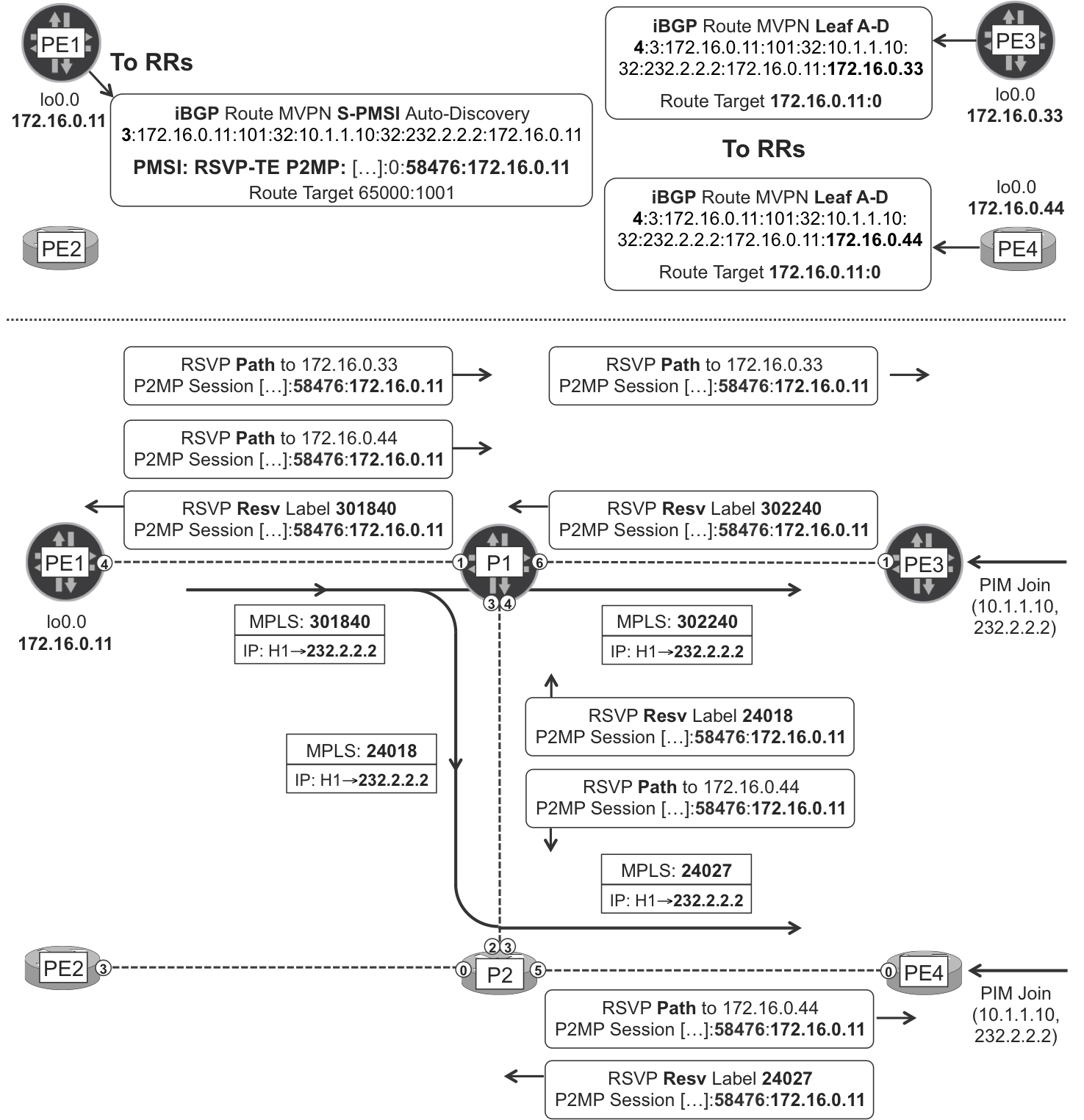
Figure 5-5. MVPN Selective P-Tunnel—signaled with RSVP P2MP
One RSVP-TE P2MP LSP is actually a set of sub-LSPs—in this case, two sub-LSPs: PE1→PE3 and PE1→PE4. The ingress PE (PE1) signals each sub-LSP independently, so there are two different Path messages from PE1 to P1. On the way back, P1 realizes that the P2MP LSP identifier is the same in both sub-LSPs and sends one single Resv message up to P1. This is very similar to the way LDP P2MP works at the branch LSRs.
One common way to call these sub-LSPs is Source to Leaf (S2L).
Finally, the leaf PEs (PE3 and PE4) receive RSVP-TE Path messages whose P2MP LSP Tunnel IPv4 Session has a value that perfectly matches the PMSI attribute of the BGP route. This is how the leaf PE binds the RSVP-TE P2MP sub-LSP to VRF-A.
Leaf AD routes
Let’s have a look at the leaf AD route sent by Junos PE3:
Example 5-44. Type 4—leaf AD route—PE3 (Junos)
juniper@PE3> show route advertising-protocol bgp 172.16.0.201
             match-prefix "4:*" detail
[...]
bgp.mvpn.0: 9 destinations, 14 routes (9 active, ..., 0 hidden)
* 4:3:172.16.0.11:101:32:10.1.1.10:32:232.2.2.2:172.16.0.11:172.16.0.33/240
[...]
   Communities: target:172.16.0.11:0

VRF-A.mvpn.0: 9 destinations, 14 routes (9 active, ..., 0 hidden)
# Same route here – omitted for brevity
The NLRI format is 4:<S-PMSI-A-D_NLRI>:<RECEIVER_PE_ROUTER_ID>. Type 4 (leaf AD) routes are sent as a response to Type 3 (S-PMSI AD) routes. Their meaning is I want to become a leaf of this S-PMSI that you advertised. So, the receiver PE simply takes the prefix of the S-PMSI AD route to which it is replying, and inserts it in the leaf AD route prefix.
As for the route target, it contains the router ID of PE1—the sender PE that originated the S-PMSI AD route—and always number zero. PE1 automatically creates a global policy (one common policy for all the VRFs) to import routes with this route target.
Example 5-45. Internal policy at sender PE—PE1 (Junos)
juniper@PE1> show policy
                  __vrf-mvpn-import-cmcast-leafAD-global-internal__
Policy __vrf-mvpn-import-cmcast-leafAD-global-internal__:
    Term unnamed:
        from community
          __vrf-mvpn-community-rt_import-target-global-internal__
                                         [target:172.16.0.11:0]
        then accept
    Term unnamed:
        then reject
This RT is slightly different from the one used in Type 7 (Source Tree Join) routes, which contained a non-zero VRF identifier. So, how does PE1 find the VRF to which the leaf AD route belongs? When PE3 copies the original S-PMSI AD route into the leaf AD prefix, it is basically mirroring a NLRI that PE1 had locally assigned to VRF-A. Thus, the RT does not require any extra information apart from PE1’s router ID.
Let’s have a look at the leaf AD route sent by IOS XR PE4, shown in Example 5-46.
Example 5-46. Type 4—leaf AD route—PE4 (IOS XR)
RP/0/0/CPU0:PE4#show bgp ipv4 mvpn advertised
[...]
Route Distinguisher: 172.16.0.44:101    /* This is the local RD */
[4][3][172.16.0.11:101][32][10.1.1.10][32][232.2.2.2][172.16.0.11]
                                                 [172.16.0.44]/224
[...]
  Attributes after outbound policy was applied:
[...]
    extended community: RT:172.16.0.11:0 SEG-NH:172.16.0.44:0
RSVP-TE P2MP state at the sender PEs
As the following example demonstrates, the sender PE maintains one RSVP-TE session per sub-LSP:
Example 5-47. RSVP-TE P2MP LSP at the ingress PE—PE1 (Junos)
juniper@PE1> show rsvp session p2mp ingress
Ingress RSVP: 2 sessions
P2MP name: 172.16.0.11:101:mv1:VRF-A, P2MP branch count: 2
To            From         State  Style Labelin Labelout LSPname
172.16.0.33   172.16.0.11  Up        SE       -   301840
                           172.16.0.33:172.16.0.11:101:mv1:VRF-A

172.16.0.44   172.16.0.11  Up        SE       -   301840
                           172.16.0.44:172.16.0.11:101:mv1:VRF-A
Total 2 displayed, Up 2, Down 0
The sub-LSPs are linked together into one single P2MP LSP, thanks to the common P2MP LSP Tunnel IPv4 Session object, whose Tunnel ID is displayed as port here:
Example 5-48. P2MP Session object at the ingress PE—PE1 (Junos)
juniper@PE1> show rsvp session p2mp detail
             name 172.16.0.11:101:mv1:VRF-A
[...]
  Port number: sender 1 receiver 58476 protocol 0
[...]
  Port number: sender 1 receiver 58476 protocol 0
As a result, PE1 does not need to replicate the packet. One single copy of the packet is pushed out to P1, as illustrated in Example 5-49.
Example 5-49. Forwarding state at the ingress PE—PE1 (Junos)
juniper@PE1> show route table VRF-A.inet.1 match-prefix "232.2.2.2*"

VRF-A.inet.1: 5 destinations, 5 routes (5 active, ...)
+ = Active Route, - = Last Active, * = Both

232.2.2.2,10.1.1.10/64*[MVPN/70] 01:12:14
                    > to 10.0.0.3 via ge-2/0/4.0, Push 301840
The mechanics are the same in IOS XR sender PEs. The format of the LSP dynamic names is different, though, as you can see here:
Example 5-50. RSVP-TE P2MP LSP at the ingress PE—PE2 (IOS XR)
RP/0/CPU0:PE2#show mpls traffic-eng tunnels auto-tunnel brief

         TUNNEL NAME         DESTINATION      STATUS  STATE
     ^tunnel-mte1009         172.16.0.11          up  up
     ^tunnel-mte1009         172.16.0.33          up  up
     ^tunnel-mte1009         172.16.0.44          up  up
     ^tunnel-mte1011         172.16.0.33          up  up
     ^tunnel-mte1011         172.16.0.44          up  up
^ = automatically created P2MP tunnel [...]
In Example 5-50, ^tunnel-mte1009 is the Inclusive Tunnel rooted at PE2, whereas ^tunnel-mte1011 is a Selective Tunnel also rooted at PE2.
RSVP-TE P2MP state at the Transit LSRs
P1 is a branching point for the Selective Tree that carries the (10.1.1.10, 232.2.2.2) flow.
Example 5-51. RSVP-TE P2MP LSP at the Transit P—P1 (Junos)
juniper@P1> show rsvp session transit p2mp
[...]
P2MP name: 172.16.0.11:101:mv1:VRF-A, P2MP branch count: 2
To            From         State  Style Labelin Labelout LSPname
172.16.0.33   172.16.0.11  Up        SE  301840   302240
                           172.16.0.33:172.16.0.11:101:mv1:VRF-A

172.16.0.44   172.16.0.11  Up        SE  301840    24018
                           172.16.0.44:172.16.0.11:101:mv1:VRF-A
[...]
P1 is replicating the packets toward PE3 and P2. Finally, P2 is not a branching point and therefore only displays one branch for this Selective Tree rooted at PE1.
Example 5-52. RSVP-TE P2MP LSP at the Transit P—P2 (IOS XR)
RP/0/CPU0:P2# show mpls forwarding labels 24018
Local  Outgoing  Prefix         Outgoing   Next Hop    Bytes
Label  Label     or ID          Interface              Switched
------ --------- -------------- ---------- ----------- --------
24018  24027     P2MP TE: 58476 Gi0/0/0/5  10.0.0.11    2170
RSVP-TE P2MP state at the receiver PEs
Because there is no PHP for P2MP LSPs, the receiver PEs pop the MPLS label and replicate the packet toward their C-Multicast interfaces with receiver state for the (10.1.1.10, 232.2.2.2) flow.
BGP Multicast VPN with Ingress Replication
Multicast was invented as a method to efficiently replicate traffic in a network. Ingress Replication (IR) is at the opposite end: the sender PE (ingress PE) sends one different copy of each C-Multicast packet to each of the remote receiver PEs. Each packet copy is targeted to one receiver PE and it travels in a P2P (or MP2P, in the case of LDP) LSP.
Imagine a sender PE with just one core uplink interface and 1,000 receiver PEs. With P2MP LSPs, the sender/ingress PE just needs to send one copy of each C-Multicast packet out of the core uplink. With IR, however, it needs to send 1,000 copies!
Despite its extreme inefficiency in the forwarding plane, IR has a use case. Because you can use the same LSPs for transporting the C-Unicast and the C-Multicast packets, from a signaling perspective, IR can be totally transparent for the transit LSRs. This facilitates deploying an MVPN service without having to touch the configuration of the P-routers. For fast, ad hoc deployments or in multivendor networks with legacy implementations that do not support P2MP LSPs in an interoperable manner, this can be an advantage.
In the terms of Table 4-1, there are many IR flavors depending on the *-to-point tunneling technology used. Here is the list:
-
For GRE Unicast, it is S2, A3, C3, E3 over E1, T0, Y1. This is MPLS-over-GRE-over-IP Unicast, and it is beyond the scope of this book.
-
For LDP, it is S2, A3, C3, E3, T2, Y2.
-
For RSVP-TE, it is S2, A3, C3, E3, T3, Y1.
-
For regular node-segment SPRING, it is S2, A3, C3, E3, T4, Y2.
-
For traffic-engineered SPRING, it is S2, A3, C3, E3, T4, Y1.
The good news is that the MVPN configuration and signaling are the same for all of these different flavors.
Inclusive PMSI—IR
Let’s begin with Inclusive PMSIs and then move on to Selective PMSIs.
IR I-PMSI configuration
Following is the Junos configuration of an IR Inclusive Tunnel rooted at PE1:
Example 5-53. Inclusive Tunnel based on IR—PE1 (Junos)
routing-instances {
    VRF-A {
        provider-tunnel {
            ingress-replication label-switched-path;
}}}
This configuration reuses the existing *-to-point LSPs without signaling any new LSPs. If you want to signal new *-to-point LSPs, which are dedicated to this service, you can also specify a template (this option is available for RSVP-TE P2P only).
Here is the IOS XR configuration of an IR Inclusive Tunnel rooted at PE2:
Example 5-54. Inclusive Tunnel based on IR—PE2 (IOS XR)
1     multicast-routing
2      vrf VRF-A
3       address-family ipv4
4        bgp auto-discovery ingress-replication
5        mdt default ingress-replication
6     !
The configuration of IR Selective Trees is left as an exercise for the reader.
IR I-PMSI signaling
Figure 5-6 illustrates the IR Inclusive Tree rooted at PE1. Note that the label value advertised by PE1 is irrelevant for this P-Tunnel; it would be relevant for the Inclusive Trees rooted at other PEs. As for the LDP-PEx labels, they are mapped, hop by hop, to the IPv4 unicast FEC 172.16.0.xx/32 (refer back to Figure 2-3 and Figure 2-4).
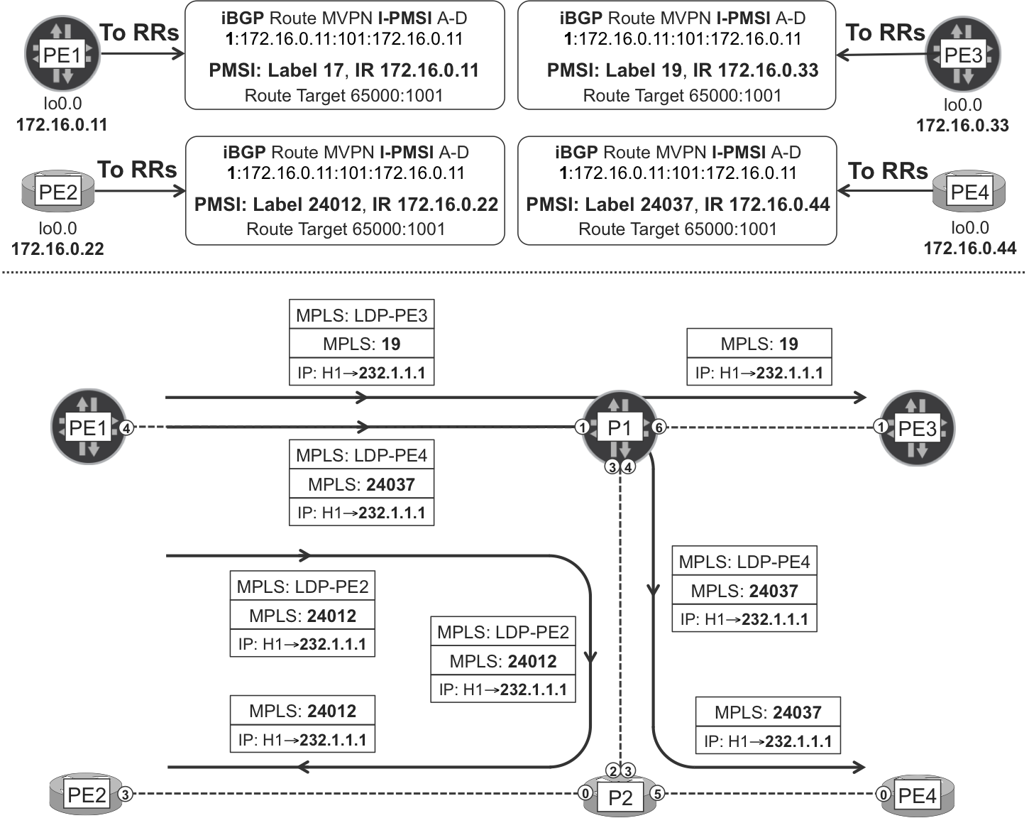
Figure 5-6. MVPN Inclusive P-Tunnel—IR
The forwarding mechanism for each packet is similar to IPv4 VPN Unicast: double push at the ingress PE, and PHP of the transport label. In this example, the MPLS transport protocol is LDP, but it could be a different one, as well.
In Junos, each sender PE can freely choose the P-Tunnel technology of its own rooted PMSIs. There is one exception to this rule: Inclusive IR P-Tunnels.
Looking back at Figure 5-6, PE1 knows what service MPLS label to push by looking at the Intra-AS PMSI AD route of the remote PEs. In other words, the IR Inclusive Tree rooted at PE1 requires the remote PEs (PE2, PE3, and PE4) to also be themselves the root of an IR Inclusive Tree.
Selective PMSI—IR
IR Selective Trees are not affected by this restriction. They are signaled with a similar albeit slightly different strategy:
-
S-PMSI AD routes carry PMSI attribute with Label 0 and Tunnel Type IR.
-
Leaf AD routes carry a PMSI attribute with non-zero Label and Tunnel Type IR.
Unlike Figure 5-6, in which the leaf router advertises the downstream service label via the I-PMSI AD route, in the Selective PMSI, the label is signaled in a separate leaf AD route. This makes it possible for a Junos PE to be the root of an I-PMSI based on mLDP or on RSVP-TE P2MP while being a leaf of an IR S-PMSI.
BGP Multicast VPN with Other P- Tunnel Flavors
The Tunnel Type encoded in the PMSI attribute can also be PIM, and all of the PIM modes (SSM, ASM, and BIDIR) are defined in RFCs 6513 and 6514. In the terms of Table 4-1, this model is S2, A3, C3, E2, T1, [Y3 for SSM, Y4 for ASM and BIDIR].
PIM signals the P-Tunnels, which are based on multipoint GRE. Although this model is very similar to draft Rosen at the transport level (P-PIM and GRE), C-Multicast signaling is the responsibility of BGP and not C-PIM, so it is genuinely BGP Multicast VPN. In the terms of Table 4-1, draft Rosen is A1, C1 (not A3, C3).
Finally, mLDP MP2MP is also an available option (S2, A3, C3, E3, T2, Y4), but as of this writing it is only implemented on IOS XR.
CE Multihoming in BGP Multicast VPN
Egress PE Redundancy
When C-Receivers are multihomed to several PEs, the same mechanisms discussed around Figure 4-4 apply. There is nothing specific to BGP MVPN in that respect.
Ingress PE Redundancy
Let’s suppose that H2 (10.1.2.20) is multihomed in an active-active model. CE1 and CE2 advertise the 10.1.2.0/24 IPv4 route with the same attributes—Local Preference, MED, and AS Path—to PE1 and PE2, respectively. The Root PEs do not change these attributes, so they prefer the eBGP route to the iBGP route. With these conditions, both PE1 and PE2 advertise an RD:10.1.2.0/24 route to the RRs.
Now, both PE3 and PE4 have downstream C-Multicast receivers of (10.1.2.20, 232.1.1.1) at VRF-A. Do they target the Source Tree Join route to PE1 or to PE2? If this is the first time you ask yourself this question, you might find the answer somewhat surprising.
This is called the Upstream Multicast Hop (UMH) selection process. According to RFC 6513: “the default procedure [...] is to select the route whose corresponding Upstream PE address is numerically highest.” This is actually the default implementation in Junos. It means that PE3 targets its Source Tree Join to PE2, regardless of the IGP metric toward the Upstream PEs. In other words, Unicast and UMH are not congruent when it comes to selecting the Upstream PE for C-Multicast traffic.
During this book’s tests, it was observed that the default implementation of IOS XR and Junos differ. PE4 also targets its Source Tree Join to PE2, but for a different reason: PE4’s best unicast route toward the source is via PE2, due to the lower IGP metric. In other words, Unicast and UMH are congruent by default in IOS XR. You can achieve this behavior in Junos by using the configuration command set routing-instances VRF-A protocols mvpn unicast-umh-election.
Aligning Unicast to UMH has some risks, and it is good to know them well so that you can work around them. In this example, PE1 and PE2 both advertise the unicast IPv4 VPN route RD:10.1.2.0/24. With the IGP metric as a tie-breaker, the preferred BGP next hop toward 10.1.2.0/24 in VRF-A is 172.16.0.11 for PE3, and 172.16.0.22 for PE4. So, PE3 and PE4 target the Source Tree Join to PE1 and PE2, respectively. What is the impact?
-
If the C-Multicast flow is transported in (S, G) Selective Trees, PE3 is a leaf of PE1’s S-PMSI only, and PE4 is a leaf of PE2’s S-PMSI only. As a result, there is no traffic duplication at the receivers and the service is fine. This cannot be guaranteed for Wildcard (*, G) or (*, *) S-PMSI, though.
-
If the C-Multicast flow is transported in Inclusive Trees, the Source Tree Join that PE3 sends to PE1 is enough for PE4 to receive the C-Multicast traffic tunneled by PE1. Likewise, the Source Tree Join that PE4 sends to PE2 is enough for PE3 to receive the C-Multicast traffic tunneled by PE2. The result is traffic duplication at PE3 and PE4. But, does that affect the service?
PE3 and PE4 may implement an RPF mechanism to discard the traffic arriving from the wrong Upstream PE. This is possible if each P2MP LSP has a different egress MPLS label, which is always the case in IOS XR and it requires vt- interfaces in Junos (like in Example 5-4). The different label value makes it possible for the receiver PE to determine what sender PE injected the C-Multicast packet in the network. This is one key advantage of not doing PHP.
This label RPF behavior is implemented by default in IOS XR. As for Junos, it requires explicit configuration: set routing-instances <VRF_NAME> protocols mvpn sender-based-rpf. As of this writing, this knob is supported for RSVP-TE P2MP only.
This mechanism cannot work with IR Inclusive Tunnels in any of the vendors. Looking back at Figure 5-6, PE3 advertises one single I-PMSI AD route with one single service label to all the PEs. Thus, both PE1 and PE2 would push the same inner label toward PE3. This behavior, combined with the fact that IR relies on PHP, makes it impossible for PE3 to determine whether a C-Multicast packet is coming from PE1 or PE2. For this reason, IR with Inclusive Tunnels requires an active-backup unicast scheme in which all the egress PEs select the same Upstream PE.
Choosing the Best RD Scheme
The RD scheme choice is critical from the perspective of convergence. Let’s keep analyzing the scenario where the C-S (H2) is multihomed in an active-active manner.
With per-VPN RDs (<AS>:<VPN_ID>) format, the RR selects the best (from its point of view) IPv4 VPN unicast route to C-S and reflects it. As you saw in Chapter 3, this introduces a delay in unicast convergence. How about multicast? First, multicast RPF is based on unicast, and the MVPN Source Tree Join route’s RT is copied from the IPv4 VPN C-S unicast route’s RI. For this reason, multicast is equally affected by this delay. This issue is cleanly fixed with a <ROUTER_ID>:<VPN_ID> RD scheme, which brings both IPv4 VPN C-S unicast routes to the receiver PEs.
How about the MVPN routes? Source Tree Join prefixes contain the <ROOT_RD>, which is VRF’s RD at the Root PE. Imagine PE3 and PE4 target their (10.1.2.20, 232.1.1.1) joins to PE1 and PE2, respectively. With the <AS>:<VPN_ID> RD format, the Source Tree Join routes are identical and the only difference is in the RT. The RR selects one of the routes only and reflects it. That route contains just one RT, so only one of the two PEs (PE1 or PE2) receive a Source Tree Join targeted to itself. This is typically service-disruptive for the receiver PE whose Source Tree Join is not reflected. On the other hand, with the <ROUTER_ID>:<VPN_ID> RD scheme, the Source Tree Join prefixes—which contain the <ROOT_RD>—are different and the RR reflects both of them. Again, per-PE-and-VPN RDs prove more advantageous.
Now, let’s consider a pure active-backup scenario with PE1 and PE2 as primary and secondary Root PEs, respectively. There are 1,000 receiver PEs—PE3 to PE1002—for (10.1.2.20. 232.1.1), and the VRFs are configured with the <AS>:<VPN_ID> RD format. Now, imagine that the RR choses PE1002’s as the best Source Tree Join prefix. If PE1 fails, the Leaf PEs update their self-originated (10.1.2.20, 232.1.1.1) Source Tree Join routes so that the RT points to PE2. But only one of these 1,000 updates has an effect: the one coming from PE1002. This means that fast-updating Leaf PEs would need to wait for PE1002 before they can receive the flow from PE2. Again, the solution to this challenge is using a <ROUTER_ID>:<VPN_ID> RD scheme.
On a parallel note, during this book’s tests, RTC has been proven to be an efficient manner to limit the distribution of MVPN routes while maintaining the service in an interoperable manner. RTC is fully discussed in Chapter 3. As of this writing, RTC for MVPN is supported in Junos only. The design implications of this fact in a multivendor network are discussed in Chapter 6 for the L2VPN NLRI (same reasoning is applicable to the MPVN NLRI).
Note
The most scalable, responsive, and efficient MVPNs are obtained by combining per-PE-and-VPN RDs with Route Target Constraint (RTC).
BGP Multicast VPN with C-PIM ASM
After discussing the different P-Tunnel options, let’s briefly explore the C-Multicast world beyond SSM. By default, the multicast groups 232.0.0.0–232.255.255.255 (shortly stated, 232/8) are reserved for SSM mode.
If you want multicast groups outside the 232/8 range to also behave in SSM mode, you need to do the following:
-
In Junos, declare them explicitly. For example:
set routing-instances VRF-A routing-options multicast ssm-groups 226/8. -
In IOS XR, it just works. An equivalent command exists, but it is not required in this book’s tests.
ASM Mode
In ASM mode, multicast receivers send an IGMP (*, G) Report and rely on the network to discover the C-Sources and bring the C-Multicast flow down. It’s easier said than done: for the network, the complexity of the task is much higher!
A special router called Rendezvous Point (RP) performs source discovery and converts (*, G) into (S, G) join state. Rendezvous is French for meeting, and it is a nice metaphorical way of saying that the RP brings multicast sources and receivers together.
On one hand, the FHR encapsulates (S, G) multicast data packets into unicast PIM packets called Register-Start or simply Register. PIM Registers are sent unicast to the RP, and this is how the RP learns about the active (S, G) flows. At this point, the RP sends a Register-Stop to the FHR, so the FHR stops encapsulating every single (C-S, C-G) packet toward the RP.
On the other hand, Last Hop Routers (LHRs) process the IGMP (*, G) Reports and send PIM (*, G) Joins to their RPF neighbors en route to the RP—the LHR does not know about the source S yet. This (*, G) Join state is propagated up to the RP.
After it has information about active (S, G) flows and also downstream (*, G) receivers, the RP sends PIM (S, G) Join packets to its RPF neighbor en route to the source S. This is how the RP Tree (RPT), also known as Shared Tree, connects sources to receivers. Initially, C-Multicast traffic flows down the RPT. As soon as a LHR receives the first (S, G) data packet, it discovers the source S. At this point, the LHR can (and does by default) signal a branch of the Shortest Path Tree (SPT), also known as Source Tree, and prunes its branch from the RPT. This process is called SPT switchover.
The RP is a critical element in multicast networks and it is often redundant. In IP Multicast, the most scalable RP redundancy technique is MSDP Anycast (RFC 4611). In this model, RPs have two loopback IPv4 addresses:
-
Each RP has a different primary loopback IPv4 address, which they use to establish MSDP sessions with other RPs. MSDP (RFC 3618) is a soft-state TCP-based protocol that is capable of exchanging (S, G) Source Active messages.
-
All of the RPs have the same secondary loopback IPv4 address. All of the routers in the network consider it as the RP address, where the Registers and the (*, G) Joins go.
Note
All of the following models account for C-RP redundancy. They all rely on the loopback addressing strategy just described.
IPv4 Multicast in general and PIM in particular are complex technologies. Therefore, let’s keep the MPLS focus and see how to solve the ASM challenge in the context of the BGP Multicast VPN service.
Figure 5-7 shows four different solutions to the same challenge.
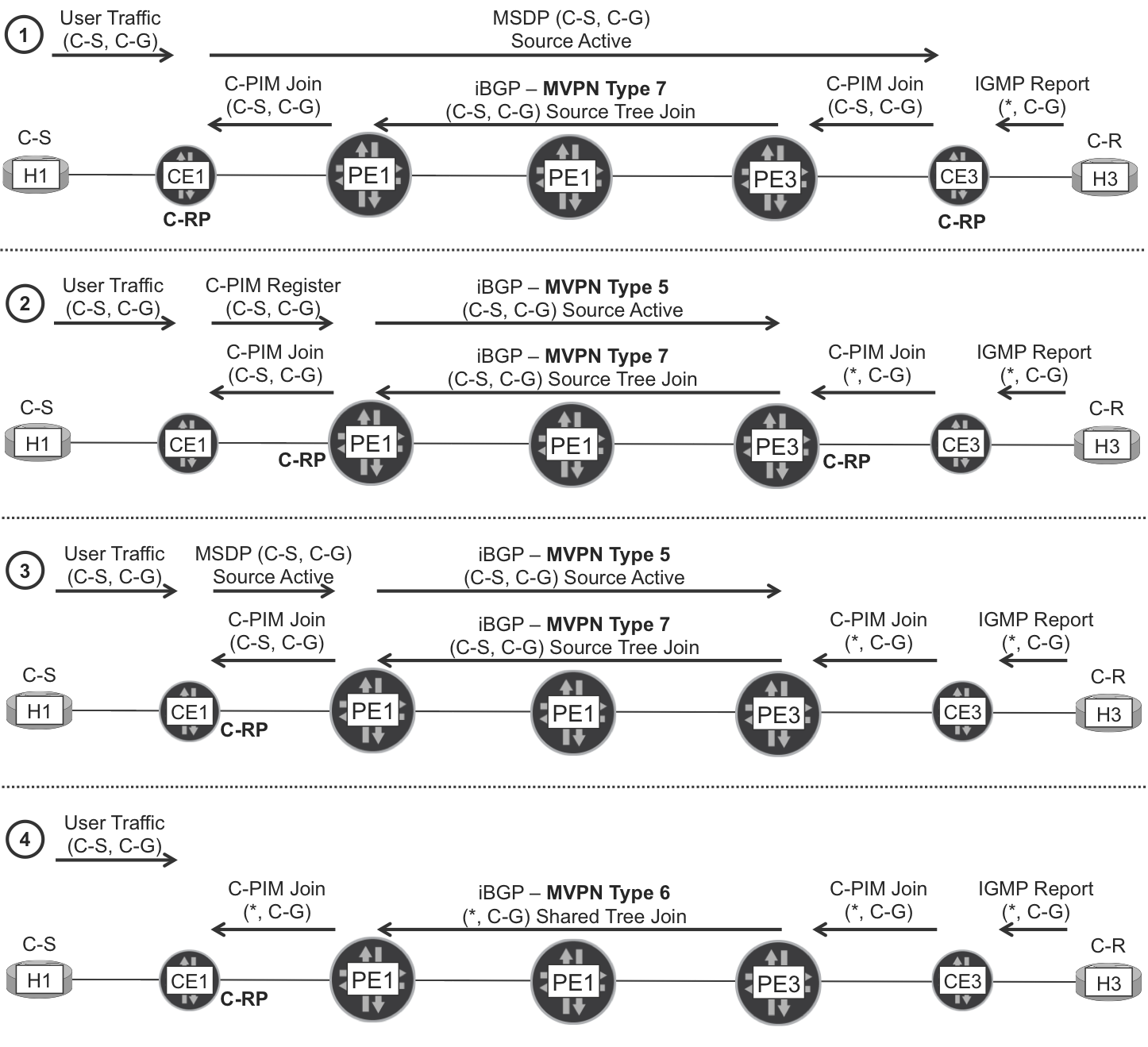
Figure 5-7. BGP Multicast VPN and C-PIM ASM—four models
Let’s take a closer look at each of them:
- Solution 1
- The Customer RPs (C-RPs) are all based on CE devices. The C-RPs exchange Source Active messages over a full mesh of MSDP sessions. A big drawback of this model is that every site in the MVPN must have a local CE acting as a C-RP: this imposes an administrative overhead to the service provider’s customer, not to mention the need to maintain an MSDP full mesh. Conversely, it is totally transparent for the SP, unless it manages the CEs.
- Solution 2
- More than one (for redundancy) PE in the MVPN has a loopback interface in the VRF acting as C-RP. The advantage of this model is that the SP’s customer only needs to point to the (same) C-RP address and completely rely on the SP to perform the C-RP role. The administrative overhead is low because there are no MSDP sessions to configure, and the extra BGP signaling is light and simple. On the down side, the customer is totally dependent on the SP even for intra-site multicast.
- Solution 3
- More than one (for redundancy) CE act as C-RPs. The C-RPs maintain a full MSDP mesh and also more than one MSDP session between a CE and the VRF loopback of a PE in the MVPN. Redundancy is ensured if there are at least two CE-PE MSDP sessions, whose CE and PE are both different. This solution makes it possible for the SP’s customer to keep the control of their C-RPs. This is a better solution than Solution 1 because it relaxes the requirement to have a CE configured as C-RP on every site. On the downside, like Solution 1 it also requires a protocol (MSDP) with manual provisioning to work.
- Solution 4
- More than one (for redundancy) CE act as C-RPs. The C-RPs maintain a full MSDP mesh, but they do not peer via MSDP with any PE. This is a simple solution for the SP’s customer, but it brings a significant complexity to the SP. From a C-Multicast perspective, this is the only model where not only the SPT, but also the Rendezvous Point Tree RPT (or Shared Tree) are signaled across the core. Then, comes the SPT switchover and many design considerations regarding the C-RP placement. What if the C-Source, the C-Receiver and the C-RP are in three different sites? It works, but the signaling is quite complex and it is beyond the scope of this book.
As of this writing, the authors have not exhaustively tested each of these options in a multivendor lab setup. However, past Junos deployment experiences rank Solution 2 as the most scalable and the less complex of them all, especially when all of the PEs in the MVPN are configured as a local C-RP. Solutions 1, 2, and 3 are supported in mvpn-mode spt-only (the default), whereas Solution 4 is supported in mvpn-mode rpt-spt.
C-Rendezvous Point—PE and CE Configuration
Let’s pick Solution 2 and provide some configuration and signaling examples.
Here is the additional configuration on a Junos CE, pointing to an external C-RP:
Example 5-55. C-RP static configuration at a CE—CE1 (Junos)
protocols {
    pim rp static address 10.10.10.10;
}
Let’s have a look at a Junos PE locally configured as a C-RP in VRF-A.
Example 5-56. C-RP local configuration at a PE—PE1 (Junos)
interfaces {
    lo0 {
        unit 1 {
            family inet {
                address 192.168.10.11/32 primary;
                address 10.10.10.10/32;
}}}}
routing-instances {
    VRF-A {
        interface lo0.1;
        protocols {
            pim {
                rp local address 10.10.10.10;
}}}}
Note
Watch local versus static. It really makes a difference.
And, finally, here is an IOS XR PE locally configured as a C-RP in VRF-A:
Example 5-57. C-RP local configuration at a PE—PE4 (IOS XR)
interface Loopback1
 vrf VRF-A
 ipv4 address 192.168.20.44 255.255.255.255
 ipv4 address 10.10.10.10 255.255.255.255 secondary
!
router pim
 vrf VRF-A
  address-family ipv4
   rp-address 10.10.10.10
!
C-Multicast Signaling—ASM Mode with C-RP at the PEs
Let’s suppose that H1 is sending C-Multicast packets (10.1.1.10, 225.0.0.1). By default, 225.0.0.1 is an ASM C-G address.
PE3 and PE4 receive C-PIM (*, 225.0.0.1) Joins and/or IGMP (*, 225.0.0.1) Reports at their downstream interfaces. But, they cannot originate a (C-S, 225.0.0.1) Source Tree Join BGP route until they learn at least one C-S (in this case, 10.1.1.10).
PE1 has that information because it received (C-S, C-G) C-PIM Registers from CE1. Then, PE1 sends a new MCAST-VPN route: Type 5—(S, G) Source-Active AD.
Example 5-58. Type 5—(C-S, C-G) Source-Active AD route—PE1 (Junos)
juniper@PE1> show pim statistics instance VRF-A

PIM Message type        Received       Sent  Rx errors
V2 Register                 2667          0          0
V2 Register Stop               0         50          0

juniper@PE1> show route advertising-protocol bgp 172.16.0.201
             match-prefix "5:*" detail
[...]
bgp.mvpn.0: 9 destinations, 16 routes (9 active, ..., 0 hidden)
* 5:172.16.0.11:101:32:10.1.1.10:32:225.0.0.1/240 (1 entry...)
 BGP group iBGP-RR type Internal
     Nexthop: Self
     Flags: Nexthop Change
     Localpref: 100
     AS path: [65000] I
     Communities: target:65000:1001

VRF-A.mvpn.0: 9 destinations, 16 routes (9 active, ..., 0 hidden)
# Same route here – omitted
The format of this (S, G) Source-Active AD route is 5:<RD>:<C-S_LENGTH>:<C-S_ADDRESS>:<C-G_LENGTH>:<C_G_GROUP>. The prefix only contains C-Multicast information.
The Source-Active AD route is targeted to all of the PEs in the MVPN. As soon as PE3 and PE4 receive it, they can signal (C-S, C-G) Source Tree Join routes and the rest of the story is the same as in the SSM examples.
The interoperability of this Solution 2 was successfully tested.
Noncongruent C-Unicast and C-Multicast
Long before BGP Multicast VPN was proposed, there was one thing called Multicast BGP. It is first mentioned in the precursor of RFC 4760 - Multiprotocol Extensions for BGP-4 as Network Layer Reachability Information used for multicast forwarding.
Interestingly, it is a set of unicast address families, which you can see in Table 5-2.
| AFI | SAFI | Junos family | Junos tables | IOS XR family |
|---|---|---|---|---|
| 1 | 2 | inet multicast |
inet.2 |
ipv4 multicast |
| 1 | 129 | inet-vpn multicast |
bgp.l3vpn.2 and<vrf-name>.inet.2 |
vpnv4 multicast |
| 2 | 2 | inet6 multicast |
inet6.2 |
ipv6 multicast |
| 2 | 129 | inet6-vpn multicast |
bgp.l3vpn-inet6.2 and <vrf-name>.inet6.2 |
vpnv6 multicast |
What is the purpose of these address families? PIM (S, G) Join and BGP (S, G) Source Tree Join are targeted to the RPF neighbors en route to the multicast Source. Similarly, PIM (*, G) Join and BGP (*, G) Source Tree Join are targeted to the RPF neighbors en route to the Rendezvous Point.
Multicast RPF is tightly coupled to unicast routing. This usually elicits two questions: what is my RPF neighbor en route to the source (or the RP)? and what is the next hop if I want to send unicast packets to the source (or the RP)? Typically, they have the same answer. This is the default behavior, and it can be changed. Actually, sometimes it makes sense to decouple RPF from unicast routing. And this is when these address families become handy.
Figure 5-8 illustrates a use case. The CE-PE connections are not straight; instead, there is an L2 (Ethernet) transport provider in the middle. These connections do not support the transport of multicast Ethernet frames. As a result, the only way to transport multicast packets between CE1 and PE1, or between CE3 and PE3, is by encapsulating them within unicast frames. There are basically two options: extending MPLS to the CEs, or using GRE-over-IP unicast tunnels as PE-CE access interfaces at the VRF (in other words, as ACs). The first model is nice and scalable, but it requires a significant architectural change. The second model, with all its limitations, can fit into a quick deployment and it is used by some SPs.
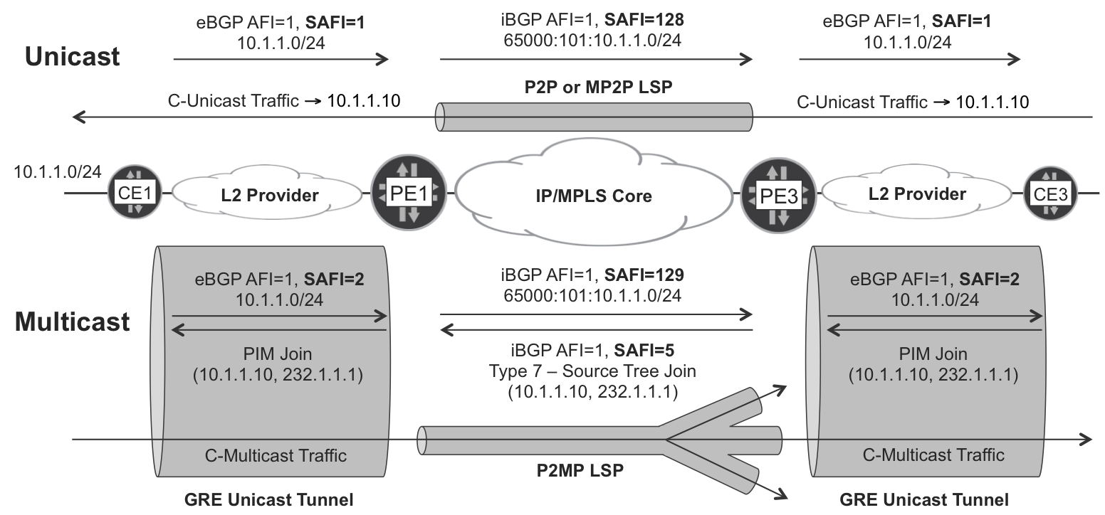
Figure 5-8. Incongruent Unicast and Multicast topology—use case
In this case, it is important that you use the GRE tunnels only to transport the multicast packets. On the other hand, you can transport unicast packets natively. This is a motivation to keep two separate unicast topologies or RIBs: one for unicast forwarding, and another one for multicast source RPF.
Note
To achieve interoperability, Junos routers require the rfc6514-compliant-safi129 knob on all the BGP neighbors supporting SAFI 129.
If you look back at Table 5-1 and Figure 5-1, they should make more sense now than they might have when you first saw them. It’s time to move on from L3 multicast services, and explore another universe: L2VPN.