
Chapter 6. Point-to-Point Layer 2 VPNs
In all of the MPLS services discussed in previous chapters, the entire service provider (SP) network acts like a distributed router from the perspective of the SP’s customer. These are Layer 3 (L3) MPLS services. The Ingress PE removes the original Layer 2 (L2) header and looks at the packet’s L3+ information. On its way out to the destination CE, the Egress PE pushes a new L2 header. Both the ingress and the egress PE have L3 addresses on the attachment circuits, which might rely on different L2 technologies.
On the other hand, in L2 services, the SP acts like a distributed switch, whose ports are the PEs’ attachment circuits. And there is no L2 global public service equivalent to the Internet, so all the L2 MPLS services are actually VPNs.
L2VPN in a Nutshell
Figure 6-1 has outer headers on top, and it compares the forwarding plane of L3 and L2 VPNs (with P1 performing PHP). This is an all-Ethernet example—both on the access circuits and on the underlying core links—so it does not provide the full picture. It conveys the main idea, though: the customer frame’s L2 information is preserved. This is not a hard statement: in reality, the user frame’s L2 header can actually change. For example, in Ethernet L2VPNs, it is a frequent practice to manipulate the frame’s VLAN tags at the Label Edge Routers (LERs); but key information like the source or destination MAC address is typically preserved—although it can be tunneled in certain L2VPN flavors.
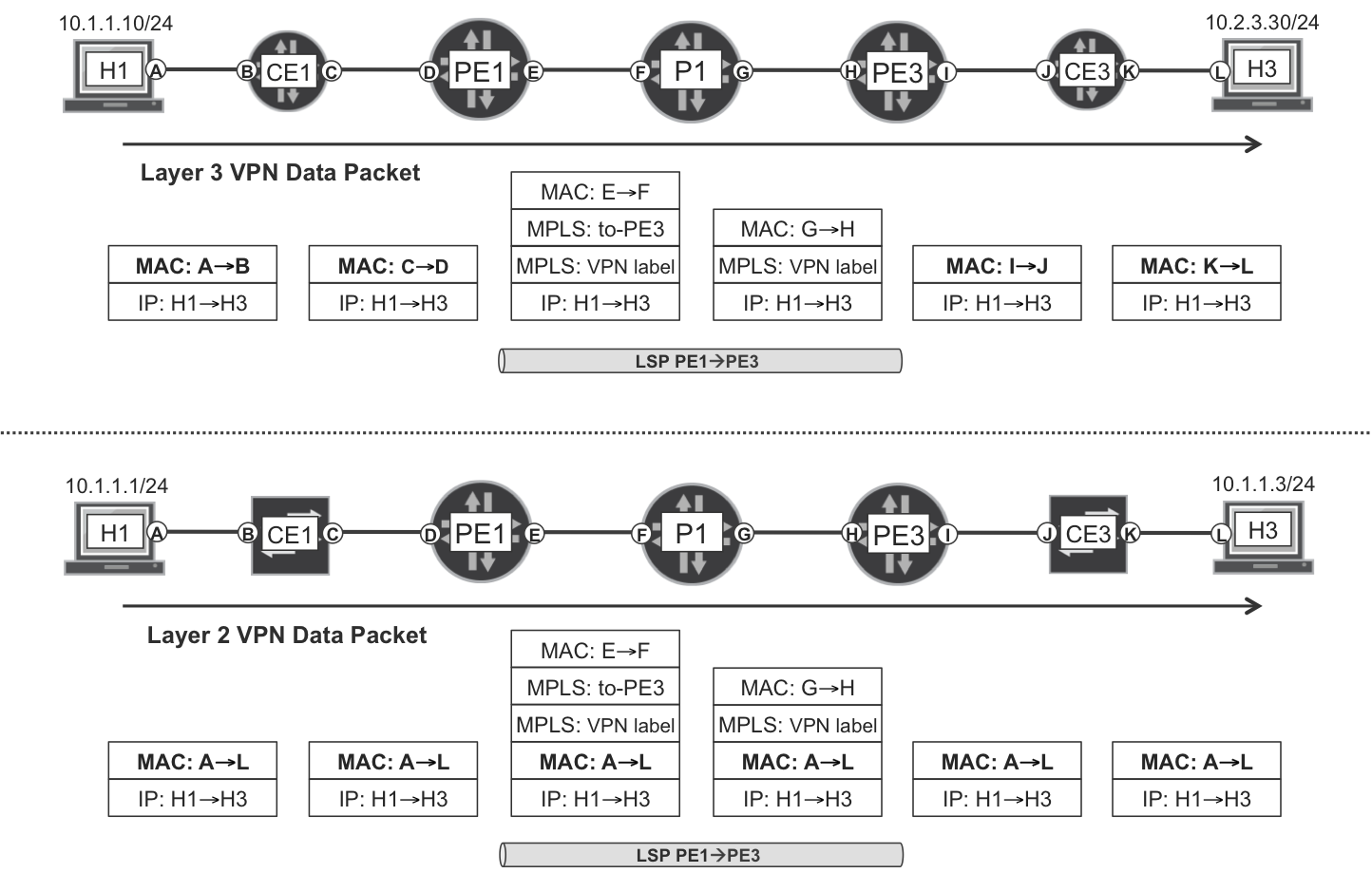
Figure 6-1. L3 and L2VPNs—forwarding plane
L2VPN Use Cases
Among the many use cases for L2VPN, two of them are especially relevant.
Corporate WAN and data centers
Like L3VPN, L2VPN can be a service that a traditional SP offers to its customers. These customers can be enterprises or small cloud providers that have a couple of things in common:
-
They cannot afford or do not want to pay for their own WAN infrastructure.
-
They need an L2 overlay to stretch their L2 domains among physically distant sites.
Data centers are a powerful example. Traditionally, data center architectures relied on flat L2 connectivity. As data centers scale with more traffic and virtual machines (VMs), while they also become geographically distributed, legacy L2 bridging is no longer an option.
Let’s look at the data center WAN use case. This is a popular application often called Data Center Interconnect (DCI). Many enterprises and cloud providers place gateways at the edge of each data center. These act as L2VPN PEs interconnected through a central IP/MPLS core. From the perspective of a data center gateway, the local data center network infrastructure plays the role of a CE or a set of CEs. And the IP/MPLS core interconnects the different data centers. L2VPN not only helps to scale, it also provides virtualization so different tenants or end customers can share the same data center—or set of data centers.
This virtualization capability is also the reason why L2VPN has another powerful use case: inside each data center for scalable server and application connectivity. In this scenario, though, most often the intra–data center L2VPN PEs are interconnected via an IP fabric (or an MPLS fabric) rather than a classic IP/MPLS core. We will explore this topic in Chapter 10; for the moment, let’s get back to MPLS.
DCI is not the only reason why an organization might purchase L2VPN services from an SP. For example, some customers build their own WAN links by purchasing L2VPN services from SPs. The SP becomes a pure transport provider and the customer uses the L2VPN as if it were an L2 link that interconnects two of the customer’s core devices. Why do that? In this way, the customer could build its own MPLS core! Although this MPLS over L2 over MPLS architecture might sound like science fiction, it is a common practice: many small and medium-sized organizations already use this nested overlay approach (although they do not really have visibility of the inner MPLS layer, which is transparently implemented by the transport provider).
Backhauling—L2VPN as a transport
Although L2VPN is definitely a popular commercial service offered to customers for many applications (e.g., DCI or WAN emulation), SPs also use internal L2VPNs as part of their own infrastructure: L2VPN as a transport in aggregation networks. This is a common approach to backhaul both mobile and wireline traffic.
Figure 6-2 represents a classic architecture. Note that the Customer and Service VLAN are optional: it is also possible to backhaul with one or zero VLAN tags. Using both tags is great for multiplexing, though.
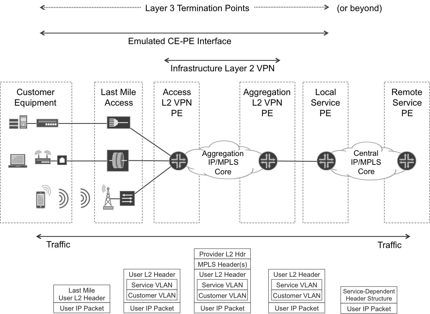
Figure 6-2. Backhauling—L2VPN as a transport
The Metro Ethernet Forum (MEF) has defined some standards and mechanisms (such as OAM) necessary to achieve carrier-class behavior in a Carrier Ethernet network.
The last-mile access device is typically a translational L2 bridge whose customer-facing interfaces might or might not be pure Ethernet. On the left side of Figure 6-2, you can see the following:
-
A corporate customer with a DSL connection that transports Ethernet over ATM
-
A residential customer with a native Ethernet FTTH (Fiber to the Home) connection
-
A 4G mobile user with a non-Ethernet microwave connection
These are just a few examples to illustrate the variety of access technologies. The last-mile access device hides all this complexity by translating CE→PE customer frames or cells into Ethernet frames and forwarding them up to the aggregation network. Likewise, PE→CE Ethernet frames are translated into the appropriate L2 format and sent down to the customer device. The manipulation of the original L2 headers can range from no action (such as in some FTTx implementations) to a significant translation logic. But it remains L2 bridging.
The Local Service PE may in turn provide an L3 service (Internet, IP VPN, etc.). In this case, the access L3 endpoints are the CE and the Local Service PE.
Or, the Local Service PE may provide an L2VPN Service; this is why in Figure 6-2 the right-side L3 Termination Point is labeled or beyond. In this case, the concepts of L2VPN as a Transport and L2VPN Service are totally orthogonal to each other. L2VPN as a Transport relates to how the SP transports L2 frames from CE to Local Service PE, and this should be transparent for the customer. On the other side, the L2VPN Service is what the customer purchases: L2 connectivity between its sites. In Figure 6-2, the Local Service PE sees the CE-PE interface as an L2 straight attachment circuit. How the L2 frames are actually transported inside the aggregation network is quite transparent to the Local Service PE. In that sense, the Infrastructure (Transport) L2VPN is just an overlay.
In more modern architectures, some of the functions depicted in Figure 6-2 are collapsed as follows:
-
The same device can perform the last-mile access and Access L2VPN PE functions. This is just an internal implementation at the last-mile access device, which gets promoted from a L2 bridge to a L2VPN PE.
-
The same device may perform the Aggregation L2VPN PE and Local Service PE functions. This interesting dimension (called PWHE) is explored later in this chapter.
L2VPN Topological Classification
L2VPNs can be Point-to-Point (P2P) or Multipoint-to-Multipoint (MP2MP). This concept is service-centric, not transport-centric, and it refers to the number of sites that a given L2VPN can have:
-
P2P L2VPNs can have only two sites, which may be redundant or protected. These L2VPNs are commonly called Pseudowire Edge-to-Edge Emulation (PWE3), or Virtual Private Wire Service (VPWS), or E-Line, or Virtual Leased Line (VLL).
-
MP2MP L2VPNs can have more than two sites. Depending on the topology, they are called E-Tree or E-LAN. Other popular terms such as Virtual Private LAN Service (VPLS) or Ethernet VPN (EVPN) are specific to certain flavors and do not represent the MP2MP L2VPN technology as a whole.
Another important concept is that of a pseudowire (PW). Paraphrasing RFC 6624, “the entity that connects two attachment circuits across the SP network is called a pseudowire.” In the context of the previous service classification, P2P L2VPNs rely on a single PW, and some flavors of MP2MP L2VPNs rely on a set of PWs.
Ethernet frames can be forwarded in the context of any of these two L2VPN topologies. Indeed, Ethernet is a multiaccess technology and it supports both. An MP2MP Ethernet L2VPN service behaves like a distributed switch with more than two ports, so it performs MAC learning. Conversely, P2P Ethernet L2VPNs do not require MAC learning because they are like a distributed hub with two ports (like a pipe): whatever the ingress PE receives on port #1, the egress PE simply sends it out of port #2, and vice versa.
Non-Ethernet L2 technologies are typically P2P in nature, so these can only be transported by using P2P L2VPNs.
L2VPN Signaling and Transport
Like L3VPNs, modern L2VPNs decouple the service from the transport by using MPLS label stacking: the outer label takes the tunneled packets to the egress PE, and the inner label identifies the VPN service.
Note
In L2VPN literature, a Transport LSP is often called a Packet-Switched Network (PSN) Tunnel. We use both terms in this book interchangeably. But is a PSN Tunnel a Pseudowire? No! Actually, a Pseudowire is a bidirectional service element that uses at least two unidirectional PSN Tunnels (maybe more if redundancy is required) for transport.
Two protocols are capable of signaling the service labels: Multiprotocol BGP and Targeted LDP. In general, you can choose one or the other, after you’ve evaluated the pros and cons, with one exception: the latest L2VPN flavor (EVPN) is only supported in BGP.
As for the PSN Tunnels, they are simply MPLS LSPs so all of the options discussed in Chapter 2 apply here, too: LDP, RSVP-TE, BGP-LU, and SPRING.
P2P L2VPN—Varied Access Technologies
The mechanisms to signal a P2P L2VPN are quite agnostic of the L2 technology that needs to be transported. After you have chosen the signaling protocol (BGP or Targeted LDP), the message exchange required to establish an Ethernet or a non-Ethernet P2P L2VPN are practically identical. The only difference lies in a protocol attribute that encodes the L2 technology type for the VPN. This attribute is either an extended community (BGP) or a TLV (Targeted LDP).
As for the forwarding plane, L2 frames or cells are encapsulated in MPLS by using a collection of methods that are specific to each technology:
-
Ethernet L2VPN forwarding is covered in RFC 4448 - Encapsulation Methods for Transport of Ethernet over MPLS Networks.
-
There are equivalent RFCs for other L2 technologies: HDLC/PPP over MPLS (RFC 4618), Frame Relay over MPLS (RFC 4619), and ATM over MPLS (RFC 4717).
These forwarding plane RFCs belong to a collection of standards that are frequently referred to as Martini encapsulation, for Luca Martini. They explain how to encapsulate L2 frames or cells in MPLS. Actually, it is possible to go even one step further and simulate leased lines by encapsulating Time Division Multiplexing (TDM) data in packets over MPLS. This technology is commonly called Circuit Emulation Services (CES), and it has several flavors. For traditional Digital Signal (DS): Structure-Agnostic TDM over Packet (SAToP, RFC 4553) and Structure-Aware TDM Circuit Emulation Service over Packet Switched Network (CESoPSN, RFC 5086). These are implemented and widely deployed in a variety of physical interfaces such as E1/T1, OC3/STM1, and OC12/STM4. As for mapping native SONET/SDH frames into packets, the model is described in RFC 4842, but the authors are unaware of any production-ready implementation.
CES is very important in mobile backhaul legacy applications such as 2G and 3G requiring TDM transport. The TDM circuits begin at the base stations and are terminated on the BSC (Base Station Controller) or the RNC (Radio Network Controller). Timing and packet order requirements are typically quite strict for TDM, which motivates the usage of a control word. This concept is presented later in this chapter and can also be used in other L2VPNs services like Ethernet.
L2VPN versus L1VPN
L2VPNs and L3 (three) VPNs have many things in common: tunneling and transporting data between CE-facing attachment circuits, label stacking, and so on.
On the other hand, the L2VPN and L1 (one) VPN concepts are completely different. L2VPN is a service that uses the IP/MPLS core as an overlay, whereas L1VPN is a technology aimed to build the core underlay. L1VPN and Generalized MPLS (GMPLS) are widely deployed technologies, but they fall outside the scope of this book.
The IP/MPLS core underlay can be based on Ethernet, on TDM, or on any other L2 technology. Figure 6-1 shows an Ethernet L2VPN service and also an Ethernet underlay, but this is just a coincidence; the L2VPN service flavor is totally independent from the underlying L2 technology used at the IP/MPLS core links.
Note
CES is an L2VPN service; its concept is the reverse of L1VPN.
L2.5 VPN
An interesting variation is L2.5 VPN, where each attachment circuit is based on a different L2 technology—for example, Ethernet on one endpoint and ATM on the other endpoint. The L2.5 VPN service automatically performs frame/cell conversion while leaving the payload (e.g., the IPv4 packet with its IPv4 header) untouched. The L2.5 term comes from the fact that there is L2 media conversion—a traditional function of routers—but no L3 lookup.
Circuit Cross-Connect and Translational Cross-Connect
For many years, Junos has supported an L2VPN flavor called Circuit Cross-Connect (CCC), which does not require any service signaling (no BGP, no Targeted LDP). Indeed, with CCC the service and the transport are not decoupled and each transport LSP (or PSN tunnel) is dedicated to one service: linking two remote attachment circuits via the IP/MPLS core. CCC signals exclusive RSVP-TE LSPs that cannot be shared with other services. This service-to-transport 1:1 relationship allows bringing up the L2VPN without the intervention of any service signaling protocol (BGP or LDP). On the downside, no autodiscovery is available for CCC and coupling the service to transport is less scalable.
Translational Cross-Connect (TCC) is CCC applied to L2.5VPN. This book does not cover CCC and TCC in detail. You will often see the CCC acronym, though: the interface encapsulation used for L2VPN is [vlan-]ccc. Indeed, the forwarding plane is the same for CCC and for modern L2VPN.
L2VPN Flavors Covered in This Book
This book covers L2VPNs whose service and transport are decoupled. This means that regardless of the protocol used to signal the service (BGP or LDP), the transport LSP can be signaled with any of the available protocols: LDP, RSVP-TE, BGP-LU, or SPRING.
Although this L2VPN set fully supports the transport of Ethernet frames, the P2P flavors also support the transport of other data in a wide variety of formats: frames, cells, and CES. Looking forward, all of this chapter’s examples feature the transport of Ethernet frames. Not a hard constraint: the variety of solutions is still overwhelming! Table 6-1 lists the Ethernet L2VPN flavors addressed in this book.
| Flavor | Topology | Signaling protocol | RFC | MAC learning |
|---|---|---|---|---|
| VPWS | Point-to-point | BGP | 6624 | N/A |
| VPWS | Point-to-point | Targeted LDP | 4447 | N/A |
| VPLS | Multipoint | BGP | 4761 | Forwarding plane |
| VPLS | Multipoint | Targeted LDP | 4762 | Forwarding plane |
| EVPN | Multipoint | BGP | 7432 | Control plane |
Note
A recent acronym for BGP-based L2 Services is BESS, which stands for BGP-Enabled Services.
All of these Ethernet L2VPN flavors rely on the same forwarding-plane encapsulation, as defined in RFC 4448 - Encapsulation Methods for Transport of Ethernet over MPLS Networks. The differences are in the signaling plane. When referring to Martini, it is important to differentiate between Martini encapsulation (RFC 4448 in the case of Ethernet) and Martini transport or signaling (RFC 4447, LDP VPWS). The latter is just one of the several L2VPN flavors that rely on the Martini encapsulation.
There are also L2VPN flavors based on a different encapsulation called Provider Backbone Bridging (PBB) or MAC-in-MAC on the AC side. This requires some extensions for VPLS (VPLS-PBB, RFC 7041) and for EVPN (EVPN-PBB, RFC 7623). The latter is briefly discussed in Chapter 8.
For the moment, let’s stick to the classic Martini encapsulation.
Note
This chapter focuses on L2VPN with MPLS forwarding plane in the core. Non-MPLS encapsulations such as VXLAN are discussed in Chapter 8, Chapter 10, and Chapter 11.
VPWS Signaled with BGP
BGP VPWS is commonly known as Kompella L2VPN, because draft-kompella-l2vpn-l2vpn was the precursor to RFC 6624. As of this writing, Kireeti Kompella, who keeps making important contributions to both MPLS and SDN, is the CTO of Juniper’s Development and Innovation team. The forwarding plane of BGP VPWS is based on Martini encapsulation (RFC 4448).
Probably the best way to understand BGP VPWS technology is to see it at work. In Figure 6-3, the CEs are no longer L3 routers but L2 switches. Initially, the following links are administratively down in order to prevent L2 loops: CE1-PE2, CE2-PE1, CE3-PE4, and CE4-PE3.
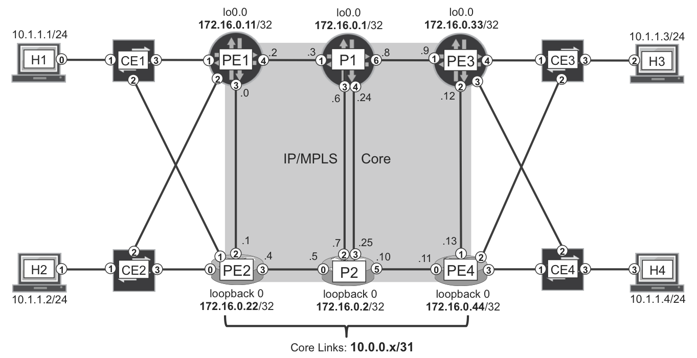
Figure 6-3. L2VPN—physical topology
As in the previous chapter, inter-PE links PE1-PE2 and PE3-PE4 have a high IGP metric, so they are not used for transit in the absence of core link failures.
Let’s bring up a BGP VPWS service, and later explore CE multihoming in depth. The L2 service goes like this: CE1—PE1—PE4—CE4. When it is correctly provisioned, H1 and H4 can resolve each other’s MAC addresses (via ARP) successfully, so ping between H1 and H4 succeeds.
BGP L2VPN Address Family
BGP VPWS and BGP VPLS both use the same multiprotocol BGP address family: AFI=25, SAFI=65. Let’s call it the L2VPN address family.
Here is the additional configuration at a Junos PE:
Example 6-1. L2VPN address family configuration—PE1 (Junos)
protocols {
    bgp {
        group iBGP-RR {
            family l2vpn signaling;
}}}
Adding this configuration to all the BGP groups also does the trick on Junos RRs.
The additional configuration on IOS XR PEs is shown in Example 6-2.
Example 6-2. L2VPN address family configuration—PE2 (IOS XR)
router bgp 65000
 address-family l2vpn vpls-vpws
 !
 neighbor-group RR
  address-family l2vpn vpls-vpws
!
Note
On RRs running IOS XR, you also need to add the route-reflector-client knob under each neighbor[-group] adddress-family.
BGP VPWS Configuration at the PEs
Let’s begin with the simplest VPWS example, featuring a PW that interconnects these two ACs: PE1’s ge-2/0/1 and PE4’s GigabitEthernet0/0/0/3. All of the Ethernet frames entering one of these physical ports exits unchanged from the remote AC. As you can see, this PW is somehow stretching a physical wire between two CEs. Other, more flexible, models are described later.
The original frames can be untagged or VLAN-tagged. In the latter case, the VLAN tags are transported end to end because they are considered as part of the payload.
Example 6-3 the configuration of the PE1—PE4 PW at the Junos PE1 side.
Example 6-3. BGP VPWS configuration with physical AC—PE1 (Junos)
1     interfaces {
2         ge-2/0/1 {
3             mtu 2000;
4             encapsulation ethernet-ccc;
5             unit 0;
6         }
7     }
8     routing-instances {
9         L2VPN-A {
10            instance-type l2vpn;
11            interface ge-2/0/1.0;
12            route-distinguisher 172.16.0.11:1010;
13            vrf-target target:65000:1010;
14            protocols {
15                l2vpn {
16                    encapsulation-type ethernet;
17                    interface ge-2/0/1.0;
18                    site CE1-A {
19                        site-identifier 1;
20                        ignore-mtu-mismatch;
21                        interface ge-2/0/1.0 {
22                            remote-site-id 4;
23    }}}}}}
As with any BGP-based VPN service, the Route Distinguisher (RD, line 12) format can be <IP>:<#> or <AS>:<#>. But we strongly recommend using the <IP>:<#> format for L2VPN prefixes, especially in CE multihoming topologies.
Note that the configuration does not include the remote PE address. BGP takes care of the autodiscovery!
The local and remote sites (lines 19 and 22, respectively) are L2VPN CE-IDs. They are numbered here according to the CE to which the attachment circuit is connected.
Let’s take care of the maximum transmission unit (MTU) now. One of the stickiest L2VPN interoperability challenges between Junos and IOS XR is setting and negotiating the PW MTU. When the negotiated MTU is not the same at both ends of a PW, typically the PW does not come up due to MTU mismatch.
There are two options to overcome this challenge:
- Configuring the endpoints to ignore MTU mismatch
- This is achieved both in Junos and IOS XR by using the knob
ignore-mtu-mismatch. Actually, in IOS XR there are two knobs:ignore-mtu-mismatchfor LDP-based L2VPNs, andignore-mtu-mismatch-adfor BGP-based L2VPNs. The latter is hidden, so it does not autocomplete and does not show up in the running configuration even if it’s set. - Configuring a matching MTU on both ends
- This has the advantage of providing more control, but both vendors have implementation gaps. Setting an explicit MTU is only available for some of the L2VPN flavors; and this flavor subset is different for each vendor.
A negotiated MTU is not really enforced on the traffic. The actual PW’s MTU is determined by the MTU of the local and remote ACs as well as the core links. L2 traffic cannot be fragmented, so it is very important to set the AC physical links’ MTU large enough to account for a standard IP packet (1,500 bytes), plus the Ethernet and VLAN headers. Furthermore, core links need to account for RFC 4448 encapsulation and for MPLS headers, too. In this book’s examples, it is assumed that all of the access interfaces are configured with a physical MTU of 2,000 bytes (line 3), and the core links with a MTU of at least 2,100 bytes.
In both Junos and IOS XR, sometimes a configuration change on the PW MTU does not have an immediate effect, and the PW needs to be deleted and added again or deactivated/activated in order for the change to take effect.
Note
The approach used in this book is to ignore MTU mismatches (line 20). In addition, one more Junos knob might help to work around negotiation mismatch issues: ignore-encapsulation-mismatch.
Example 6-4 the configuration for the PE1—PE4 PW at the IOS XR PE4 side.
Example 6-4. BGP VPWS configuration with physical AC—PE4 (IOS XR)
1     interface GigabitEthernet0/0/0/3
2      mtu 2000
3      l2transport
4     !
5     l2vpn
6      ignore-mtu-mismatch-ad
7      xconnect group myL2VPN
8       mp2mp L2VPN-A
9        vpn-id 123456789
10       mtu 1986
11       l2-encapsulation vlan
12       autodiscovery bgp
13        rd 172.16.0.44:1010
14        route-target 65000:1010
15        signaling-protocol bgp
16         ce-id 4
17          interface GigabitEthernet0/0/0/3 remote-ce-id 1
18    !
Note
Strictly speaking, a physical mtu 2000 does not necessarily mean the same on Junos and on IOS XR. Whether the Ethernet header is taken into account or not depends on the implementation.
The IOS XR configuration hierarchy in line 8 (mp2mp) supports a collection of BGP VPWS services, each with a different [local ce-id, remote ce-id] pair. VPWS is actually P2P, and it does not perform proper Ethernet bridging or MAC learning. So despite the mp2mp term, you can think point to point.
The vpn-id (line 9) is mandatory but its value is arbitrary because it is not signaled with BGP. Its value is only relevant when targeted LDP (and not BGP) is the protocol responsible for signaling the service.
How about the MTU? In some L2VPN flavors, IOS XR performs two MTU checks:
-
The local PW’s MTU must match the MTU advertised by the remote end.
-
The local AC’s MTU must match the locally configured PW’s MTU.
The ignore-mtu-mismatch-ad knob (line 6) helps to bypass the first check in BGP L2VPN, whereas the second check—if present—needs a little more work.
Why is the PW’s MTU (line 10) different from the AC’s MTU (line 2)? If you take line 10 off Example 6-4, the PW goes down (see Example 6-5.
Example 6-5. Automatic AC MTU computation—PE4 (IOS XR)
RP/0/0/CPU0:PE4#show l2vpn xconnect group myL2VPN detail | i MTU
        AC MTU Mismatch
    MTU 1986; XC ID 0x3881ef5; interworking none
The value in line 3 is dynamically computed from the physical MTU and must be configured explicitly on the PW (Example 6-4, line 10). This extra step is only required on a minority of the L2VPN flavors.
BGP VPWS Signaling
After they’re configured, PE1 and PE4 advertise one L2VPN BGP route each.
Example 6-6 the BGP L2VPN route advertised by Junos PE1.
Example 6-6. L2VPN route advertised by PE1 (Junos)
1     juniper@PE1> show route advertising-protocol bgp 172.16.0.201
2                  table L2VPN-A.l2vpn.0 detail
3
4     L2VPN-A.l2vpn.0: 2 destinations, 3 routes (2 active, ...)
5     *  172.16.0.11:1010:1:3/96 (1 entry, 1 announced)
6      BGP group iBGP-RR type Internal
7         Route Distinguisher: 172.16.0.11:1010
8         Label-base: 800012, range: 2, offset: 3, status-vector: 0x0
9         Nexthop: Self
10        Flags: Nexthop Change
11        Localpref: 100
12        AS path: [65000] I
13        Communities: target:65000:1010
14                     Layer2-info: encaps: ETHERNET, control flags:[0x2]
15                                  Control-Word, mtu: 0
16                                  site preference: 100
The /96 mask is internal in Junos and not advertised via iBGP: you can safely ignore it.
The NLRI in line 5 contains the RD, the advertised local CE-ID (1) and the lowest numbered remote CE-ID (3) to which this advertisement applies. This value is equal to the offset in line 8.
Line 8 contains the MPLS label information. PE1 is allocating two labels (range: 2). The mathematical rule to calculate the label is as follows:
-
Label = Label base + (Remote CE-ID – offset)
-
Frames from remote CE-ID 3 (
CE-ID = offset = 3) should arrive to PE1 with MPLS label 800012 (Label base + 0 = 800012). -
Frames from remote CE-ID 4 (
CE-ID = offset + 1 = 4) should arrive to PE1 with MPLS label 800013 (Label base + 1 = 800013).
In this P2P L2VPN, there is just one remote CE from the perspective of PE1 and its CE-ID is 4. This is why you can see label 800013 in Figure 6-4, but not label 800012. Out of the two labels (800012 and 800013), only one is used in this P2P L2VPN. So what’s the point of advertising a label block?
Note
This is not the first appearance of a label block in this book. You might remember the SRGB concept from Chapter 2. In SPRING, each destination SID is reachable with one different label. In BGP L2VPN, each source CE-ID can be identified by one different label.
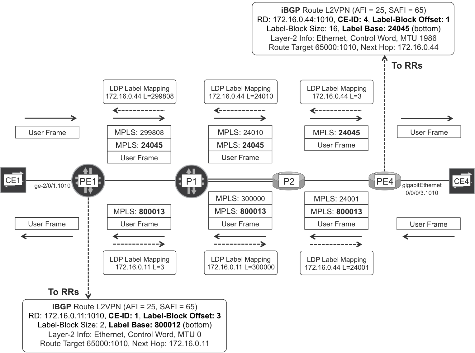
Figure 6-4. BGP VPWS signaling with LDP-based PSN Tunnel
Not only can you define several sites inside the same L2VPN instance, you can also declare several interfaces under the same site. For example, imagine there are two logical interfaces connecting CE1 to PE1—which might be on the same or in different physical links. In this case, you can connect (CE-ID 1, interface A) to remote CE-ID 3, and also connect (CE-ID 1, interface B) to remote CE-ID 4. This is still a VPWS service that connects each link from CE1 to one and only one remote CE. One single label block would be enough to achieve the two parallel VPWS services.
On the other hand, the L2VPN NLRI is also used for MP2MP L2VPN, where more labels are required for MAC learning purposes—see Chapter 7. Instead of defining two different L2VPN NLRIs, one for P2P and one for MP2MP, there is just one NLRI for both purposes, and that is another reason why you see a label block here.
The Layer2 Info extended community (lines 14 and 15) contains all the information about the attachment circuit and the way frames must be encapsulated in the MPLS core. This community must be consistent on both ends for the PW to come up.
Example 6-7 shows the L2VPN route advertised by IOS XR PE4, as seen from Junos RR1.
Example 6-7. L2VPN route advertised by PE4 (IOS XR)
1     juniper@RR1> show route receive-protocol bgp 172.16.0.44
2                  table bgp.l2vpn.0 detail
3
4     bgp.l2vpn.0: 2 destinations, 4 routes (...)
5        172.16.0.44:1010:4:1/96 (2 entries, 1 announced)
6          Accepted
7          Route Distinguisher: 172.16.0.44:1010
8          Label-base: 24045, range: 16, offset: 1, status-vector: 0x7F 0xFF
9          Nexthop: 172.16.0.44
10         Localpref: 100
11         AS path: I
12         Communities: target:65000:1010
13                      Layer2-info: encaps: ETHERNET, control flags:[0x2]
14                                   Control-Word, mtu: 1986
Line 8 contains the MPLS label information. PE4 is allocating 16 labels (range: 16). Following is what the lowest and highest numbered labels are for:
-
Frames from remote CE-ID 1 (
CE-ID = offset = 1) should arrive to PE4 with MPLS label 24045 (Label base + 0 = 24045). -
Frames from remote CE-ID 16 (
CE-ID = offset + 15 = 16) should arrive to PE1 with MPLS label 24060 (Label base + 15 = 24060).
In this P2P L2VPN, there is just one remote CE from the perspective of PE4 and it is CE-ID is 1. This is why you can see label 24045 in Figure 6-4, but not the other labels in the block (24046 up to 24060).
At this point, the PW is correctly established:
Example 6-8. PW established between PE1 (Junos) and PE4 (IOS XR)
juniper@PE1> show l2vpn connections instance L2VPN-A
[...]
Instance: L2VPN-A
Edge protection: Not-Primary
  Local site: CE1-A (1)
    connection-site           Type  St     [...] # Up trans
    4                         rmt   Up     [...] 1
      Remote PE: 172.16.0.44, Negotiated control-word: Yes
      Incoming label: 800013, Outgoing label: 24045
      Local interface: ge-2/0/1.0
      Status: Up, Encapsulation: ETHERNET

RP/0/0/CPU0:PE4#show l2vpn xconnect group myL2VPN detail

Group myL2VPN, XC L2VPN-A.4:1, state is up; Interworking none
  Local CE ID: 4, Remote CE ID: 1, Discovery State: Advertised
  AC: GigabitEthernet0/0/0/3, state is up
    Type VLAN; Num Ranges: 1
    Outer Tag: 1010
    VLAN ranges: [123, 123]
    MTU 1994; XC ID 0x1; interworking none
[...]
  PW: neighbor 172.16.0.11, PW ID 262145, state is up (established)
      MPLS         Local             Remote
      ------------ ----------------- ----------------
      Label        24045             800013
      MTU          1986              unknown
      Control word enabled           enabled
      PW type      Ethernet          Ethernet
      CE-ID        4                 1
      ------------ ----------------- ----------------
[...]
Route Target Constraint and L2VPN
One drawback of BGP P2P L2VPN is the fact that RRs reflect a L2VPN route to all the PEs, even though there is only one remote PE at the other end of the P2P L2VPN. So, all the PEs receive the route, but only one PE imports it. Chapter 3 describes the solution to this efficiency challenge: Route Target Constrain (RTC).
Junos supports BGP L2VPN in combination with RTC. As of this writing, IOS XR allows both address families to coexist; but the distribution of L2VPN NLRI is not constrained. This means that IOS XR does not advertise specific RTC routes for the RTs configured in local L2VPNs.
Here are the possible scenarios when the L2VPN and RTC address families are both advertised on the same Multiprotocol-BGP (MP-BGP) session:
- MP-BGP session between two Junos routers
- In this case, L3VPN and L2VPN prefixes are distributed successfully in a constrained and efficient manner.
- MP-BGP session between two IOS XR routers
- In this case, L3VPN prefixes are distributed in a constrained and efficient manner; on the other hand, L2VPN prefixes are flooded as if RTC was not configured. In any case, the services work fine.
- MP-BGP session between a Junos router and an IOS XR router
- In one sense, the IOS XR router floods all of the L2VPN prefixes toward the Junos router; although this is not perfectly efficient, it keeps the L2VPN service up. In the other sense, the Junos router only sends the L2VPN prefixes toward the IOS XR router if the latter advertises a matching RTC route—this can only be a default RTC route. If the IOS XR router is a pure RR, it should be configured to advertise the default RTC route anyway: business as usual. But, if the IOS XR router is a PE, advertising the default RTC route means receiving all the L3VPN prefixes, too: this has a cost in efficiency, but it does make it possible to keep the L2VPN service up and running.
L2VPN Forwarding Plane
Junos computes L2VPN forwarding entries by using a new set of RIBs. Let’s review the Junos routing tables used by all the MPLS services described so far in this book.
Junos routing tables
Several routing tables are worth examining in the context of Junos L2VPN instances. Table 6-2 shows the equivalence between tables of different VPN services.
| Service | Global auxiliary: raw NLRIs | Instance-specific: raw NLRIs | Instance-specific: processed NLRIs |
|---|---|---|---|
| IPv4 Unicast VPN | bgp.l3vpn.0 |
<VRF>.inet.0 |
|
| IPv6 Unicast VPN | bgp.l3vpn-inet6.0 |
<VRF>.inet6.0 |
|
| IPv4 Multicast VPN | bgp.mvpn.0 |
<VRF>.mvpn.0 |
|
| IPv6 Multicast VPN | bgp.mvpn-inet6.0 |
<VRF>.mvpn-inet6.0 |
|
| BGP L2VPN | bgp.l2vpn.0 |
<L2VPN>.l2vpn.0 |
<L2VPN>.l2id.0 |
The <L2VPN> tag represents the actual name of the L2VPN instance—in this example, L2VPN-A. And the <L2VPN>.l2id table contains the resolved local and remote CE IDs: 1, 4, and so on. However, the most useful table from the forwarding perspective is actually mpls.0, which contains the routes that are later pushed to the forwarding table.
Example 6-9. L2VPN forwarding entries at PE1 (Junos)
juniper@PE1> show route table mpls.0 protocol l2vpn

mpls.0: 15 destinations, 15 routes (15 active, ...)
+ = Active Route, - = Last Active, * = Both

800013         *[L2VPN/7] 1d 11:58:41
                > via ge-2/0/1.0, Pop [...]
ge-2/0/1.0     *[L2VPN/7] 1d 09:11:58, metric2 4
                > to 10.0.0.3 via ge-2/0/4.0,
                  Push 24045, Push 299808(top) [...]
If a packet arrives with MPLS label 800013, PE1 pops the MPLS header and sends the resulting frame out of ge-2/0/1.0. Likewise, if PE1 receives a frame on ge-2/0/1.0, it pushes the MPLS service label 24045 and puts the packet on an LSP toward PE4.
L2 frame encapsulation in MPLS is a bit more complex than what you can see back in Figure 6-4. H1 sends the frame untagged to CE1, and CE1 pushes two VLAN tags (outer 1010, inner 123). As discussed, the L2VPN service transports by default the VLAN tags in a transparent manner. Following is an L2 frame from H1 to H4 as it transits the link PE1→P1.
Example 6-10. Ethernet L2VPN forwarding plane
Ethernet II, Src: MAC_PE1_ge-2/0/4, Dst: MAC P1_ge-2/0/3
MPLS Header, Label: 299808, Exp: 0, S: 0, TTL: 255
MPLS Header, Label: 24045, Exp: 0, S: 1, TTL: 255
PW Ethernet Control Word, Sequence Number: 0
Ethernet II, Src: MAC H1_Gi0/0/0/0, Dst: MAC H2_Gi0/0/0/2
    Type: 802.1Q Virtual LAN (0x8100)
# Outer VLAN header #
802.1Q Virtual LAN, PRI: 0, CFI: 0, ID: 1010
    Type: 802.1Q Virtual LAN (0x8100)
# Inner VLAN header #
802.1Q Virtual LAN, PRI: 0, CFI: 0, ID: 123
    Type: IP (0x0800)
Internet Protocol Version 4, Src: 10.1.1.1, Dst: 10.1.1.4
Internet Control Message Protocol
    Type: 8 (Echo (ping) request) [...]
Control Word
There is an extra header, called Control Word (CW), inserted between the inner MPLS header and the transported L2 frame. Its usage is described in RFC 4385 - Pseudowire Emulation Edge-to-Edge (PWE3) Control Word for Use over an MPLS PSN. As discussed in Chapter 2, label switching routers (LSRs) perform load balancing by applying a hash to certain packet fields. To know what fields to take into account for the hash, it is essential to know the packet type. But MPLS headers do not have any protocol field, so LSRs must play a guessing game:
-
IP packets have the IP version number encoded in the first nibble (four bits) of their header. Consequently, if a MPLS packet has a payload whose first nibble is number four, the LSR assumes that the MPLS payload is an IPv4 packet, without any L2 headers.
-
If the first nibble of the MPLS payload is six, the LSR assumes that it is an IPv6 packet.
Let’s suppose that the payload is an Ethernet frame whose destination MAC address’ first nibble equals four. In this case, the hash (assuming that the hardware and the configuration support hashing at the MPLS payload level) is computed as if it were an IPv4 packet. Now suppose that the fourth byte of the source MAC address—which is the tenth byte in the frame—is six, the IPv4 protocol number for TCP. The way the LSR interprets it is this is a TCP-over-IPv4 L3 packet. Which is wrong: the MPLS payload is an L2 Ethernet frame, which might in turn contain an IPv4 packet—or not! Then, the LSR looks for the source and destination TCP ports at a certain byte offset inside the frame. What the LSR interprets as TCP ports are actually certain bytes within the Ethernet payload, whose value may differ between several packets of the same flow. These packets can be load-balanced across different paths and potentially arrive to the egress PE out of order. For certain applications requiring a strict packet order, this can be a big issue. And if you think about CES, it would simply break the service.
The CW is a four-byte header whose first nibble is zero. In this way, it is guaranteed that LSRs do not load-balance two frames belonging to the same flow across different equal-cost next hops. The two ends of the PW must agree on whether they use the CW, otherwise the PW is not successfully established.
There is another use case of the CW, described in RFC 5885 - Bidirectional Forwarding Detection (BFD) for the Pseudowire Virtual Circuit Connectivity Verification (VCCV). VCCV establishes a BFD session between the two endpoints of a PW. One of the available VCCV options uses the CW as a header that precedes a raw (no IP header, no UDP header) BFD packet.
BGP VPWS—CE Multihoming to Several PEs
Imagine an L2 frame circulating in the following manner (see Figure 6-3): H3→CE3→PE3→PE1→CE1→PE2→PE1→CE1, and so on, looping in a triangle with vertices CE1, PE1 and PE2. In general, L2 frames do not have a Time-to-Live (TTL) field in the L2 header, so a frame can be looping forever. Such an L2 loop scenario typically causes broadcast storms and connectivity loss, thus it is extremely undesirable. This is why redundancy is one of the touchiest aspects of L2 services in general.
Strictly speaking, there is one only clean solution to this problem: moving to L3! In L3, every time a packet traverses a device, the TTL field is decremented and when it expires the packet is dropped, which limits the impact of forwarding loops. This is not always an option for applications and services, so let’s see what alternatives are available to prevent, detect, and mitigate L2 loops.
In traditional LANs, L2 loops are prevented with Spanning Tree protocols (STP, RSTP, MSTP, etc.). If a loop takes place, it can be handled with a series of techniques: MAC move detection, broadcast storm control and mitigation, policing, automatic port disabling, and so on. Still, L2 loops do sometimes happen in L2 bridging networks, no matter how many protection measures are in place.
Now moving to L2VPN, it is possible to keep these measures in place, but just for the sake of extra protection. The L2VPN design (assuming that there are no backdoor links) should guarantee a loop-free protection even without Spanning Tree. You may add Spanning Tree on top only as an extra protection layer.
Warning
Transporting Spanning Tree frames in the L2VPN (between sites) is only a reasonable option for P2P L2VPN. It does not make sense in MP2MP L2VPN flavors where Bridge PDUs (BPDUs) would be flooded to several remote sites.
There are several multihoming options in L2VPN, and the most robust are based on Link Aggregation Group (LAG). LAGs with Link Aggregation Control Protocol (LACP) are stateful, and a CE does not switch frames between two members of a LAG, which is a great built-in way to avoid L2 loops. Here are some common approaches:
-
The CE may control the multihomed AC redundancy. For example, CE1 may group its two uplinks in a standard LAG. PE1 and PE2 both have a standard one-link LAG toward CE1, and their local System ID is different. Due to this System ID discrepancy, CE1 only activates one of the LAG’s links. If the chosen link is CE1-PE1, CE1 changes the flags of its LACP packets to PE2 to inform it that the link is not active in the LAG. The result is that PE1 flags its AC up, whereas PE2 flags its AC down. Although this solution relies on a LAG that goes to different chassis (PE1 and PE2), it is not what the industry calls a Multichassis LAG (MC-LAG).
-
The solution may be implemented on the SP, and this is a preferred option for the SP because it can take control over the critical L2 redundancy decisions. CE1 groups its two uplinks in a standard LAG, and this time PE1 and PE2 are configured with the same System ID, so CE1 sees both links as if they were connected to the same chassis. PE1 and PE2 communicate to each other over the SP core by using Inter-Chassis Communication Protocol (ICCP) and decide on whether to keep both links active or only one of them. In the all-active case—only supported in EVPN—CE1 sees both links as part of the LAG and load-balances the frames between both uplinks. In the single-active case, then if PE2 assumes the standby role—according to the ICCP negotiation—it changes the flags of its LACP packets to CE1 in order to inform it that the link is not active in the LAG. As a result, CE1 only activates its link toward PE1. This is MC-LAG. A downgraded MC-LAG without ICCP is also possible and operational (it works), but this latter model does not benefit from the possibility of having a decision point at the multi-PE side.
Note
How about not aggregating the uplinks? This is a bad idea. Allowing a CE to switch traffic between its uplinks is opening the door to L2 loops!
If either PE1 or PE2 has its local AC down—or not active in the LAG—it must signal this state accordingly to the remote PEs. Otherwise, the remote PEs might send traffic to a PE that is not able to forward the traffic to the AC, which results in traffic blackholing. Let’s see how the AC status is signaled in BGP VPWS.
BGP VPWS—PW status vector
By looking carefully at Example 6-6 and Example 6-7, you can see that PE1 (Junos) and PE4 (IOS XR) advertise a status vector as part of the NLRI. Its value is 0x0000 and 0x7FFF for PE1 and PE4, respectively. Very different!
The status vector bit length and the label block size are exactly the same. Each bit in the status vector corresponds to a label in the label block (first bit to first label, second bit to second label, etc.). Let’s see how to interpret the 0x0000 and 0x7FFF values:
-
PE4 advertises the following prefix: RD 172.16.0.44:1010, CE-ID 4, Label-Block Offset 1, Label-Block Size 16, Label Base 24045, Status Vector 0x7F 0xFF. It corresponds to local CE-ID 4, which is connected to remote CE-ID 1. The offset is precisely 1, which means that the only meaningful label for VPWS is the first one of the block (24045). And the only relevant bit of the status vector is the first one, too. In binary: 0x7F 0xFF = 01111111 11111111. The first bit is zero and it means that the local attachment circuit is up from the perspective of PE4.
-
Now, PE1 advertises the following prefix: RD 172.16.0.11:1010, CE-ID 1, Label-Block Offset 3, Label-Block Size 2, Label Base 800012, Status Vector 0x00. It corresponds to local CE-ID 1, which is connected to remote CE-ID 4. The offset is 3 and not 4, which means that the only meaningful label is the second one of the block (800013). And the only relevant bit of the status vector is the second one, too. The second bit of 0x00 is obviously zero, and it means that the local attachment circuit is up from the perspective of PE1.
Note
Despite the different way to code the unused bits of the status vector (zero in Junos, one in IOS XR) there is no interoperability issue because the meaningful bits are set accordingly: zero = up; one = down.
What happens if the attachment circuit at PE4 (interface Gi 0/0/0/3.1010) is down? In that case, PE4 advertises the L2VPN BGP route with status vector 0xFF 0xFF. All bits are set to 1, including the meaningful bit. At this point, PE1 detects the failure.
Example 6-11. PW status reflecting the received status vector—PE1 (Junos)
juniper@PE1> show l2vpn connections
[...]
Instance: L2VPN-A
Edge protection: Not-Primary
  Local site: CE1-A (1)
    connection-site           Type  St     Time last up
    4                         rmt   VC-Dn  -----
[...]
If the attachment circuit at PE1 (interface ge-2/0/1.1010) is down, PE1 advertises the L2VPN BGP route with status vector 0x40 = 01000000. Remember that the offset is 3 and the remote CE-ID is 4, so the second bit of the status vector is the meaningful one, and it is set to 1. At this point, PE4 detects the failure.
Example 6-12. PW status reflecting the received status vector—PE4 (IOS XR)
RP/0/0/CPU0:PE4#show l2vpn xconnect
XConnect               Segment 1              Segment 2
Group Name        ST   Description       ST   Description    ST
--------------------   --------------------   -----------------
L2VPN-A.4:1       DN   Gi0/0/0/3         UP   172.16.0.11    DN
Junos and IOS XR PEs both update the status vector to reflect the state of its local attachment circuits. In addition, Junos PEs also change the Layer2 Info extended community when all the local interfaces toward a given CE are down.
Example 6-13. Down “D” bit in Layer2-info extended community—PE1 (Junos)
juniper@PE1> show route advertising-protocol bgp 172.16.0.201
             table L2VPN-A.l2vpn.0 detail

L2VPN-A.l2vpn.0: 2 destinations, 3 routes (3 active, ...)
*  172.16.0.11:1010:1:3/96 (1 entry, 1 announced)
 BGP group iBGP-RR type Internal
    Route Distinguisher: 172.16.0.11:1010
    Label-base: 800004, range: 2, status-vector: 0x40, offset: 3
[..]Communities: target:65000:1010
                 Layer2-info: encaps: ETHERNET, control flags:[0x82]
                              Control-Word Site-Down, mtu: 0
                              site preference: 100
This detail is relevant for CE multihoming scenarios.
BGP VPWS multihoming at work
After understanding how the AC status is signaled with BGP, it’s time to see BGP VPWS multihoming in action. Junos supports draft-ietf-bess-vpls-multihoming, which describes BGP L2VPN active-backup multihoming scenarios such as in Figure 6-5. As of this writing, IOS XR does not support multihoming with BGP VPWS; however, it supports multihoming with LDP VPWS, as you will see later in this chapter.
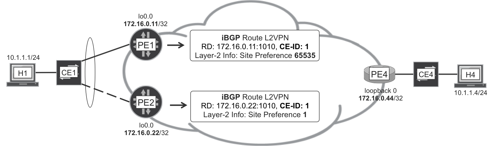
Figure 6-5. BGP VPWS—CE Multihoming
The dashed line in Figure 6-5 means that PE2 is not forwarding traffic from/to the AC. This is typically the case if the LAG is in single-active mode (the AC is logically down on PE2). But, before uplink LAGs became popular, the CE uplinks were often not aggregated, and then the standby PE (PE2) saw the AC up but did not forward traffic. BGP VPWS multihoming takes care of both scenarios, but remember that LAG uplink is a good practice whenever possible.
With BGP VPWS multihoming, one, and only one, PE is chosen as a Designated Forwarder (DF) for CE1. How? PE1 and PE2 have a CE-ID (or Site ID) assigned to their CE1-facing attachment circuits. The key is that you must configure the same CE-ID value on both PEs. Why? Because they are connected to the same CE!
The site-identifier assignment is therefore critical:
-
PE1 and PE2 both have local CE ID = 1 and remote CE ID = 4. The same local CE ID ensures that either PE1 or PE2—only one of them—is a DF.
-
PE3 and PE4 both have local CE ID = 4 and remote CE ID = 1. The same local CE ID ensures that either PE3 or PE4—only one of them—is a DF.
The election of the DF for each L2VPN site is deterministic: every PE in the network chooses the same DF for each L2VPN site. The preferred way to control the outcome of this election is to configure a site preference:
Example 6-14. BGP VPWS—site preference—PE1 (Junos)
routing-instances {
    L2VPN-A {
        protocols {
            l2vpn {
                site CE1-A {
                    site-identifier 1;
                    site-preference primary;
}}}}}
Alternatively, you can configure site-preference backup. Junos automatically sets the preference numerical values accordingly (65,535 for primary and 1 for backup).
Looking back at Figure 6-5, PE1 has a higher site preference, so it becomes the DF for CE1. Junos automatically copies the site preference—which is a numeric field in the Layer2 Info extended community—to the well-known BGP Local Preference attribute. This ensures that all of the PEs in the network—those that support draft-ietf-bess-vpls-multihoming—choose PE1 as the Designated Forwarder for CE1.
What happens if the PE1-CE1 attachment circuit goes down? PE1 advertises its L2VPN route with a modified status vector in the NLRI and, more important, with the Down “D” bit in the Layer2 Info extended community flags. Thanks to this “D” bit, all the other PEs learn that PE1 can no longer be a DF for CE1. At this point, PE2 becomes the DF for CE1, and all the PEs agree on that. Last but not least, PE1 sets the Local Preference of its L2VPN route to zero.
Note that PE1 does not withdraw its route upon PE1-CE1 failure, it only changes its attributes.
Note
It is recommended to use a <ROUTER_ID>:<VPN_ID> RD scheme in BGP VPWS scenarios with CEs multihomed to several PEs.
What if CE1 and CE4 are also connected via a direct backdoor link without the intervention of the MPLS/IP backbone? In that case, which is strongly undesirable, they would need to run a loop prevention mechanism such as Spanning Tree, both on the L2VPN and on the backdoor link. This is only an option for P2P L2VPN.
Ethernet OAM (802.3ah, 802.1ag)
Looking back at Figure 6-2, there are many reasons why the CE might lose connectivity to the Service PE, and many of them do not involve a physical link failure on the Service PE side.
If the attachment circuit on the Service PE side is L3-capable, it can run a routing or a keepalive end-to-end protocol (such as BFD) and keep track of the PE1-CE’s connection health. However, this is not always possible, especially if the Service PE provides an L2VPN service to the end customer, in which case the attachment circuit is not L3-capable.
The CE and the PE can also run LACP, even in non-multihomed scenarios (one-link LAG). Although this approach works and is gaining traction in real deployments, this is not what LACP was designed for in the first instance.
Ethernet OAM was designed for this purpose and it comes to the rescue with the following L2 tools:
- Link Fault Management (IEEE 802.3ah)
- This provides, among other things, a link-local keepalive that is exchanged between L2-capable adjacent devices.
- Connectivity Fault Management (IEEE 802.1ag)
- This provides, among other things, a hierarchical end-to-end keepalive between two remote endpoints that are not necessarily adjacent to each other.
This book does not cover Ethernet OAM interoperability but here are some notes based on the authors’ deployment experience, particulary on Junos.
You can couple an Ethernet OAM action-profile to an interface. These profiles monitor events such as [link-]adjacency-loss (no longer receiving Ethernet OAM PDUs) or [interface|port]-status-tlv (receiving a down status TLV in an incoming Ethernet OAM PDU). As a result of one of these events, the attachment circuit can be considered to be logically down even if the physical interface is up. If that happens, the local PE updates the L2VPN status vector and notifies the remote PE.
However, the remote PE does not notify its CE by changing the [interface|port]-status-tlv of its Ethernet OAM PDUs. Why? This is intentional and the goal is to avoid a deadlock where CEs prevent one another from coming up.
On a side note, an Ethernet OAM action-profile that checks for [link-]adjacency-loss is event-driven. To bring an attachment circuit logically down, the PE must stop receiving keepalives. But if keepalives have never been received on the interface, the action-profile is not executed.
BGP VPWS—VLAN Tag Multiplexing
The basic PW configured in Example 6-3 and Example 6-4 can transport native Ethernet as well as VLAN-tagged frames. There is no restriction about the number of VLAN tags, or about the outer VLAN tag’s value. However, this approach has a big drawback: the entire AC physical interface is dedicated to a single PW; or, in other words, it is dedicated to a single remote PE. The model does not allow mapping different frames to different PWs in a per-VLAN basis; and it does not allow associating certain VLANs to other services such as L3VPN. Let’s consider a more flexible model!
If you look back to Figure 6-2, the last-mile access device inserts two VLAN tags in the user frame. What are these? It is very common to refer to the outer and inner tags as Service VLAN (S-VLAN) and Customer VLAN (C-VLAN), respectively.
Typically, the S-VLAN identifies one last-mile access device. Being the outer tag, this is the only VLAN that the aggregation network cares about. The mapping is not always 1:1, and there may be several S-VLANs handled by the same last-mile access device.
The C-VLAN typically identifies one customer circuit. Imagine that the last-mile access device receives—from the upstream aggregation network—a frame whose outer VLAN tag matches one of the S-VLANs for which it is responsible. The last-mile access device (which is a bridge, not a PE) determines, according to the combination of S-VLAN and C-VLAN, the actual end customer interface to which the frame must be forwarded. In that sense, C-VLANs act as pure multiplexers.
What if you want to map one S-VLAN to one PW? Example 6-15 shows how you can do it in Junos.
Example 6-15. BGP VPWS Configuration with SVLAN AC—PE1 (Junos)
1     interfaces {
2         ge-2/0/1 {
3             mtu 2000;
4             flexible-vlan-tagging;
5             encapsulation flexible-ethernet-services;
6             unit 1010 {
7                 encapsulation vlan-ccc;
8                 vlan-id 1010;
9     }}}
10    routing-instances {
11        L2VPN-A {
12            instance-type l2vpn;
13            interface ge-2/0/1.1010;
14            route-distinguisher 172.16.0.11:1010;
15            vrf-target target:65000:1010;
16            protocols {
17                l2vpn {
18                    encapsulation-type ethernet-vlan;
19                    interface ge-2/0/1.1010;
20                    site CE1-A {
21                        site-identifier 1;
22                        ignore-mtu-mismatch;
23                        interface ge-2/0/1.1010 {
24                            remote-site-id 4;
25    }}}}}}
VLAN tags are just a multiplexing field in the VPWS world. They do not identify a bridge domain, because there is simply no intelligent bridging in VPWS. Indeed, a VPWS service is just a cross-connect between an AC and a PW.
A single VLAN tag is specified on line 8. As a result, all the following frames are transported by the VPWS service:
-
Frames with single VLAN tag 1010.
-
Frames with double VLAN tag, being 1010 the outer (SVLAN) tag. In this case, the CVLAN header is considered as part of the payload and it is preserved.
If you want to be more selective, you can use the syntax vlan-tags outer 1010 inner[-list] <CVLAN(s)>, specifying the CVLAN(s) that are mapped to the PW.
Note
For easier reading, this chapter’s examples use the same numbering for the VLAN, RT, and RD (in this case, 1010). This is arbitrary: the three numbers could just as well be all different.
Example 6-16 shows the configuration to map one S-VLAN to one PW in IOS XR.
Example 6-16. BGP VPWS Configuration with SVLAN AC—PE4 (IOS XR)
1     interface GigabitEthernet0/0/0/3
2      mtu 2000
3     !
4     interface GigabitEthernet0/0/0/3.1010 l2transport
5      encapsulation dot1q 1010
6     !
7     l2vpn
8      xconnect group myL2VPN
9       mp2mp L2VPN-A
10       vpn-id 123456789
11       l2-encapsulation vlan
12       autodiscovery bgp
13        rd 172.16.0.44:1010
14        route-target 65000:1010
15        signaling-protocol bgp
16         ce-id 4
17          interface GigabitEthernet0/0/0/3.1010 remote-ce-id 1
18    !
The handling of additional VLAN tags is the same as in Junos. If you want to be more selective, you can use the syntax encapsulation dot1q 1010 second-dot1q <CVLAN>, specifying the CVLAN that is mapped to the PW.
The two previous examples are interoperable between both vendors.
Finally, it is also possible to specify a list of S-VLANs that are mapped to a PW. Here are the changes that you would need to apply:
-
In Junos, let’s use Example 6-15 as a reference. First, replace
vlan-id(line 8) with, for example,vlan-id-list [1001-1019 2001-2009]. Then, set theencapsulation-type(line 18) toethernet. -
In IOS XR, simply configure the list on the AC itself. In Example 6-16, line 5, use the syntax
encapsulation dot1q 1010-1019.
This S-VLAN list scenario works fine in single-vendor scenarios, but, as of this writing, it does not interoperate between Junos and IOS XR. This is because Junos and IOS XR signal Ethernet and VLAN encapsulation, respectively. Neither Junos nor IOS XR allows changing the encapsulation successfully in this case, and the ignore-encapsulation-mismatch knob is only available in Junos.
There is one way to achieve interoperability, though. If the entire physical interface is reserved in the IOS XR device (Example 6-4), it interoperates successfully with Junos vlan-id-list.
BGP VPWS—VLAN Tag Translation and Manipulation
Now, put a mirror on Figure 6-2. Place it in the middle of the right-side cloud (labeled Central IP/MPLS Core) and look from the left so that you can see the same picture twice in a nice symmetrical manner. Imagine that two end customers—one on the far left and one on the far right—need to communicate to each other. The Service PEs can provide an L3 Service or an L2 Service to achieve that:
-
If they provide an L3 Service, the ingress PE strips the Ethernet header—including the VLAN tags—from the user frame, as you can see at the top of Figure 6-1.
-
In the L2 Service case, the Ethernet header—including its VLAN tags—is preserved. Now, the VLAN tags must match on the left and on the right. That is a tough provisioning challenge, and its workaround is VLAN tag translation.
Note
In the remainder of the BGP VPWS section, all the configuration examples are incomplete for the sake of brevity. To complete them, you can mix and match with Example 6-3 and Example 6-4.
In the following example, a frame with (SVLAN, CVLAN) = (1010, 123) in the PE-CE interface would have (SVLAN, CVLAN) = (2020, 123) in the PW. And if the frame has only one VLAN tag equal to 1010 on the AC, the tag would be 2020 on the PW.
Example 6-17. Rewriting the SVLAN tag in the PW—Junos, IOS XR
# PE1 (Junos)

interfaces {
    ge-2/0/1 {
        unit 1010 {
            encapsulation vlan-ccc;
            vlan-id 1010;
            input-vlan-map {
                swap;
                vlan-id 2020;
            }
            output-vlan-map swap;
}}}

juniper@PE1> show interfaces ge-2/0/1.1010 | match vlan
    VLAN-Tag [ 0x8100.1010 ]
        In(swap-swap .2020) Out(swap-swap .1010)
    Encapsulation: VLAN-CCC

# PE4 (IOS XR)

interface GigabitEthernet0/0/0/3.1010 l2transport
 encapsulation dot1q 1010
 rewrite ingress tag translate 1-to-1 dot1q 2020 symmetric
!
This technique resolves mismatched SVLAN/CVLAN values at the PW’s endpoints. Indeed, Example 6-17 interoperates fine, regardless of the AC’s VLANs.
Finally, in Example 6-18, a frame with (SVLAN, CVLAN) = (1010, 123) in the AC would have single VLAN = 123 in the PW. And if the frame has only one VLAN tag equal to 1010 on the AC, it travels with no VLAN tag through the PW.
Example 6-18. Removing SVLAN tag in the PW—Junos and IOS XR
1     # PE1 (Junos)
2
3     interfaces {
4         ge-2/0/1 {
5             unit 1010 {
6                 encapsulation vlan-ccc;
7                 vlan-id 1010;
8                 input-vlan-map pop;
9                 output-vlan-map push;
10    }}}
11    routing-instances {
12        L2VPN-A {
13            protocols {
14                l2vpn {
15                    encapsulation-type ethernet;
16    }}}}
17
18    # PE4 (IOS XR)
19
20    interface GigabitEthernet0/0/0/3.1010 l2transport
21     encapsulation dot1q 1010
22     rewrite ingress tag pop 1 symmetric
23    !
Several combinations of the pop, push, and swap actions are available and the flexibility is so nice that there is often more than one solution to each challenge.
Just note that the SVLAN-pop scenario in Example 6-18 works fine in single-vendor scenarios, but as of this writing, it does not interoperate between Junos and IOS XR. The reason is the encapsulation mismatch discussed in the context of vlan-id-list, and it is specific to the current BGP VPWS multivendor implementation.
What if the AC is configured with two VLAN tags? In that case, you can apply the pop/push actions as in Example 6-18 (lines 8 and 9) and keep encapsulation ethernet-vlan on the PW. With these settings, interoperability is successful. However, the encapsulation mismatch issue is hit if there is a double pop/push instead of a single one, for exactly the same reasons discussed earlier.
BGP VPWS—PW Head-End (PWHE)
The traditional L2VPN as a transport architecture depicted back in Figure 6-2 offers a pair of possibilities to optimize provisioning and service delivery:
-
Merging the functions of the last-mile access device and the Access L2VPN PE into a converged Access Node. This is a local implementation matter.
-
Merging the functions of the Aggregation L2VPN PE and the Local Service PE in one single Service Node device, as in Figure 6-6.
Figure 6-6. Aggregation L2VPN and Local Service PE in one device
The second evolution brings the possibility of having one unified IP/MPLS backbone. The core can be flat from the IGP perspective or, for better scaling, it can be partitioned if the Local Service PE acts as an Area Border Router (ABR) or Autonomous System Border Router (ASBR), and you can find further details in Chapter 16.
This Local Service PE may be offering different services:
- L3 Services (Internet or L3VPN)
- In this case, the Local Service PE is an L3 Endpoint: you can ignore the mention or beyond in Figure 6-6. Each VLAN or SVLAN/CVLAN transported in the PW gets mapped to a different L3 logical interface. In turn, each such L3 interface can belong to the master routing table (Internet service) or to a L3VPN.
- P2P L2VPN
- The Infrastructure PW is stitched to the Service PW. PW stitching is not discussed in detail in this book.
- MP2MP L2VPN
- There is more about this option in Chapter 7.
Let’s discuss the first use case. It is called Pseudowire Head-End (PWHE or PWH), also known as Pseudowire Head-End Termination (PWHT or PHT). Among all the acronyms, this book picks PWHE.
We are in VLAN (de)multiplexing mode: the traffic from all the customers that share the same pair (last-mile access device, Local Service PE) are grouped into one single PW. Let’s focus on just one such PW.
Back in Figure 6-2, the Aggregation L2VPN PE has one AC pointing to the right, toward the Local Service PE. Similarly, the Local Service PE has one AC per VLAN(s) pointing to the left, toward the Aggregation L2VPN PE.
Now, in Figure 6-6 both functions are collapsed into the same device, labeled as Local Service PE: let’s call it Head-End PE from now on.
Conceptually, PWHE is simply VLAN (de)multiplexing on the same PW. The only difference is that the Head-End PE—converged Aggregation L2VPN PE + Local Service PE—terminates the L2 emulated circuit, instead of switching traffic between PW and external L2 ACs.
As of this writing, both IOS XR and Junos support PWHE with LDP VPWS, but only Junos supports PWHE with BGP VPWS. The following example uses BGP VPWS, but because the Head-End role (PWHE function) is implemented on a Junos PE, the end result is interoperable. The Access L2VPN PE, which runs IOS XR, simply sees a regular L2VPN, but it has no L3 visibility of the PWHE.
The IOS XR configuration is exactly the same as in Example 6-4. The only difference is on the Head-End PE side, running Junos (see Example 6-19).
Example 6-19. BGP VPWS—PW Head-End termination—PE1 (Junos)
1     chassis {
2         pseudowire-service device-count 10;
3         fpc 0 pic 0 tunnel-services bandwidth 10g;
4     }
5     interfaces {
6         ps1 {
7             anchor-point lt-0/0/0;
8             flexible-vlan-tagging;
9             mtu 9192;
10            unit 0 {
11                encapsulation ethernet-ccc;
12            }
13            unit 1010 {
14                vlan-tags outer 1010 inner 123;
15                family inet address 10.1.1.100/24;
16    }}}
17    routing-instances {
18        L2VPN-A {
19            instance-type l2vpn;
20            interface ps1.0;
21            route-distinguisher 172.16.0.1:111;
22            vrf-target target:65000:111;
23            protocols {
24                l2vpn {
25                    encapsulation-type ethernet;
26                    interface ps1.0;
27                    site CE1-A {
28                        site-identifier 1;
29                        mtu 2000;
30                        interface ps1.0 remote-site-id 4;
31    }}}}}}
You can view each ps interface as the local termination of a PW coming from one single last-mile access device. With the previous configuration (line 2), you can define up to 10 psX interfaces (ps0 through ps9), each mapped to/from one PW. These interfaces are anchored (line 7) to an lt interface (line 3). Anchoring instantiates the psX interface in a Packet Forwarding Engine (PFE) inside the router. This makes the service actually work by associating bandwidth resources and also enabling Quality of Service (QoS).
Now, the psX.0 logical interface (lines 10 through 12) is special in that it represents the PW’s AC inside the Head-End PE (lines 20, 26, and 30). VLANs are then used as (de)multiplexers and many non-zero units (lines 13 through 15) can be created: these are the service endpoints. In this case, the service is L3 but it could be in theory L2 (not implemented yet), as well.
The L3 endpoint units such as ps1.1010 can have single or dual VLAN tags. They can be kept in the master routing table or declared in a VRF. Although as of this writing the latter is not officially supported yet, the authors’ lab testing was successful.
The logical interface ps1.1010 is static. But it is also possible to create dynamic interfaces by using VLAN autosensing, which opens the door to a very flexible broadband access and subscriber management model. The classical BNG (Broadband Network Gateway) is replaced with a Service PE that can be anywhere in the MPLS core.
BGP VPWS—Load Balancing
As you saw before, the CW is required to ensure that all the L2VPN frames of the same flow are forwarded on the same path so that they do not arrive to the destination out of order. The downside of the CW is that all the packets of the same PW may follow the same path. For some applications, this is a poor load-balancing scheme that can easily lead to traffic polarization in the core network. There are two solutions to this challenge:
- RFC 6790 - The Use of Entropy Labels in MPLS Forwarding
- It is applicable to MPLS in general (not only L2VPN) and it relies on inserting two MPLS labels just below the transport label: the Entropy Label Indicator (ELI), which is a reserved fixed label with value 7, and the entropy label itself. The full MPLS label stack from top to bottom would be: the transport label, the ELI, the entropy label, and the VPN label (if any).
- RFC 6391 - Flow-Aware Transport (FAT) of Pseudowires over a MPLS Packet Switched Network
- This is only available for L2VPN and it relies on inserting an MPLS label—a so-called flow label—at the bottom of the stack. This label lies between the L2VPN label and the Control Word.
The principle of both approaches is quite simple: entropy (or flow) labels have pseudo-random values and are not interpreted by any routers. By inserting such label(s), the ingress PE is actually adding a variable seed for load-balancing hash computation when the packet arrives to transit LSRs. The ingress PE assigns the same entropy (or flow) label value to every packet of a given flow, so packet order is guaranteed. As a result of the entropy (or flow) label, different flows in the same PW can be mapped to different equal-cost paths.
Here is what happens when the packet reaches the egress PE:
-
In the entropy label case, due to PHP the ELI is exposed (although the penultimate LSR may decide to also pop the ELI and entropy label). If needed, the egress PE removes the ELI and the entropy label, exposing the service label (if any). The packet is then mapped to the appropriate service—for example, to an L2VPN AC.
-
In the FAT scenario, due to PHP the L2VPN label is exposed. The egress PE maps the packet to the appropriate L2VPN AC, and then it pops all the remaining labels (VPN and flow label) without any further processing.
As of this writing, entropy labels were supported by Junos, but not by IOS XR. On the other hand, this book’s tests provided interoperable PW with FAT and LDP VPWS.
As for BGP VPWS, flow labels can be enabled in IOS XR but not in Junos. The result is interoperable, in the sense that PE4 pushes the flow label and PE1 is able to pop it and forward the frame successfully. In the other direction, PE1 does not push the flow label, but that is fine for PE4, too.
Example 6-20 shows the IOS XR configuration.
Example 6-20. BGP VPWS—FAT configuration—PE4 (IOS XR)
l2vpn
 xconnect group myL2VPN
  mp2mp L2VPN-A
   autodiscovery bgp
    signaling-protocol bgp
     load-balancing flow-label both static
!
VPWS Signaled with LDP
LDP VPWS is commonly known as Martini transport and, like BGP VPWS (Kompella), it relies on Martini encapsulation (RFC 4788). It is also called L2 Circuit or L2CKT.
In Chapter 2 and Chapter 4 you saw two applications of LDP: building MP2P and P2MP LSPs with IPv4 and P2MP FECs, respectively. These FECs are typically exchanged over direct LDP sessions, whose endpoints are the loopback interfaces of two directly connected neighbors. These LDP sessions are therefore not targeted.
LDP VPWS, on the other hand, requires PE-PE targeted LDP sessions:
-
If the PEs are directly connected to each other, and they already have a LDP session established to exchange other FEC types (e.g., IPv4), there is no need to signal any more LDP sessions: the existing one is used to exchange L2VPN FECs. Note that sometimes you might need to selectively filter the FECs that you want to advertise or receive: for example, the network design might rely on a given session to exchange L2VPN FECs but not IPv4 FECs, or vice versa.
-
If the PEs are several hops away from each other, a new LDP session must be established between the two PEs.
LDP VPWS Configuration at the PEs
Let’s begin with a scenario in which a physical AC is mapped to a PW. The AC configuration is skipped because it is similar to BGP VPWS (see Example 6-3, lines 1 through 7 and Example 6-4, lines 1 through 4).
Example 6-21 shows the PE1—PE4 PW configuration at Junos PE1.
Example 6-21. LDP VPWS configuration with physical AC—PE1 (Junos)
1     protocols {
2         ldp {
3             interface lo0.0;
4         }
5         l2circuit {
6             neighbor 172.16.0.44 {
7                 interface ge-2/0/1.0 {
8                     virtual-circuit-id 13579;
9                     encapsulation-type ethernet;
10                    ignore-mtu-mismatch;
11                    pseudowire-status-tlv;
12    }}}}
One key aspect of LDP VPWS is its lack of a native autodiscovery mechanism. You must configure neighbors (line 6) explicitly. Later you will see how this limitation is overcome by using BGP AD.
The service is identified by a VC ID (line 8) that must match on both ends of the PW.
The pseudowire-status-tlv usage is explained later.
Following is the PE1—PE4 PW configuration at PE4, which runs IOS XR:
Example 6-22. LDP VPWS configuration with physical AC—PE4 (IOS XR)
l2vpn
 ignore-mtu-mismatch
 pw-class PW-L2CKT-UNTAGGED
  encapsulation mpls
   protocol ldp
   control-word
   transport-mode ethernet
 !
 xconnect group myL2CKT
  p2p L2CKT-A
   interface GigabitEthernet0/0/0/3
   neighbor ipv4 172.16.0.11 pw-id 13579
    pw-class PW-L2CKT-UNTAGGED
!
LDP VPWS Signaling and Forwarding Planes
With the previous configuration, the PW comes up. Let’s verify that.
Example 6-23. Established LDP VPWS—Junos and IOS XR
# PE1 (Junos)

juniper@PE1> show l2circuit connections interface ge-2/0/1.0
[...]
Neighbor: 172.16.0.44
 Interface                 Type  St     # Up trans
 ge-2/0/1.0(vc 13579)    rmt   Up     1
   Remote PE: 172.16.0.44, Negotiated control-word: No
   Incoming label: 299776, Outgoing label: 16080
   Negotiated PW status TLV: Yes
   Local PW status code: 0x0000, Neighbor PW status code: 0x0000
   Local interface: ge-2/0/1.0, Status: Up, Encapsulation: ETHERNET
   Flow Label Transmit: No, Flow Label Receive: No

# PE4 (IOS XR)

RP/0/0/CPU0:PE4#show l2vpn xconnect group myL2CKT
XConnect               Segment 1          Segment 2
Group    Name     ST   Description     ST  Description         ST
--------------------   ------------------  ----------------------
myL2CKT  L2CKT-A  UP   Gi0/0/0/3       UP  172.16.0.11  13579  UP
-----------------------------------------------------------------
In IOS XR, you can use the show l2vpn xconnect detail option in order to see the local and remote PW status TLV values. The following couple of tips can help you to interpret the output of both Junos and IOS XR commands:
-
Local PW Statusin Junos means the same asOutgoing PW Statusin IOS XR: the advertised PW Status TLV value. -
Neighbor PW Statusin Junos means the same asIncoming Statusin IOS XR: the received PW Status TLV.
Figure 6-7 shows an example in which the transport LSP is signaled by using LDP. This is just one option and all the other transport protocols are also available. Indeed, LDP-based L2VPNs can also be transported with RSVP-TE, BGP-LU, and SPRING-signaled LSPs, as well as with IP (e.g., GRE) tunnels.
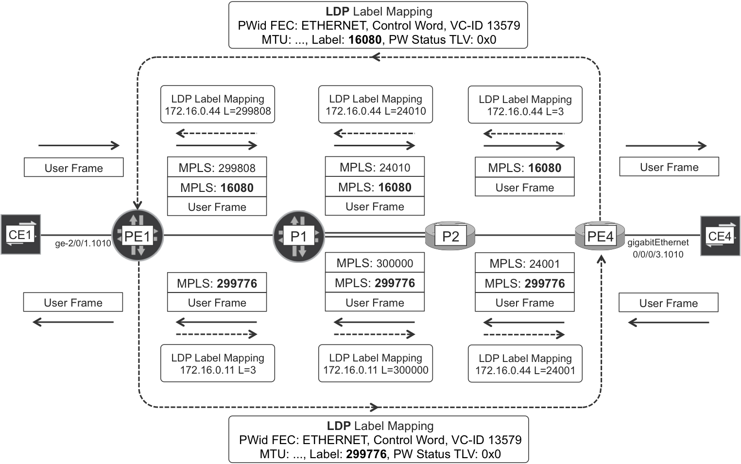
Figure 6-7. LDP VPWS signaling with LDP-based PSN Tunnel
Note
LDP PWid FEC has type 0x80 = 128. It is popularly called FEC 128 or Martini FEC.
The forwarding plane is the same as in BGP VPWS. Just one note about the CW: by default, an LDP VPWS whose endpoints run Junos negotiate to use the CW, whereas two IOS XR PEs negotiate not to use it. As a result, in a multivendor PW with one PE running Junos and the other running IOS XR, there is no CW unless the IOS XR PE is explicitly instructed to use it (Example 6-22).
LDP VPWS—CE Multihoming and PW Redundancy
The concepts were already discussed in the context of BGP VPWS. With the FEC 129 model, discussed in Chapter 7, it is possible to deploy the same multihoming mechanisms as in BGP VPWS, but let’s see what can be done with plain FEC 128.
LDP VPWS—PW Status TLV
Back in BGP VPWS, there was a Status Vector that accounted potentially for several VPWS connections to different local CEs. In the LDP VPWS case, each PW only connects two CEs, so there is no need to have a vector. However, the PW Status TLV that optionally accompanies each PWid FEC is actually a vector. This time, the bits do not represent several remote CEs, but different aspects of the status of a single PW. This makes it possible to provide richer information than just the up/down state. A perfect PW Status TLV has all bits set to zero, and any non-zero bits reflect an exceptional condition whose interpretation is ruled by the following standards:
-
RFC 4446 - IANA allocations for PWE3, defines the following values: PW forwarding (clear all failures) (0x0), PW not forwarding (0x01), local AC receive fault (0x02), local AC transmit fault (0x04), local PSN-facing PW receive fault (0x08), and local PSN-facing PW transmit fault (0x10).
-
RFC 6870 - Pseudowire Preferential Forwarding Status Bit, defines the following values: PW forwarding standby (0x20), and PW request switchover (0x40). These values are quite relevant for PW redundancy solutions.
The PW Status TLV is advertised in two types of LDP messages: in LDP Label Mapping during PW establishment, and in LDP Notification messages when there is a status change.
The usage of these bits is not unified across vendors. For example, if an AC is down from the point of view of LACP (on an active-backup LAG), Junos signals 0x01 (PW not forwarding) and IOS XR signals 0x06 (local AC receive and transmit faults). The reaction on the remote end is the same, though: considering the PW as down from a forwarding-plane perspective.
LDP VPWS—PW redundancy configuration
Let’s suppose that PE1 signals a VPWS service and both PE3 and PE4 are two valid endpoints. For example, both PE3 and PE4 are connected to the same CE, or they both provide L3 PWHE, or they both can stitch PWs (PE1-PE3 or PE1-PE4) to the next L2VPN hierarchy level.
Unlike BGP VPWS, traditional (FEC 128) LDP VPWS has no native autodiscovery so if PE1 needs to have PW redundancy toward both PE3 and PE4, you need to configure these PWs manually. In the configuration shown in Example 6-24 Junos PE1 chooses PE4 as primary and PE3 as standby.
Example 6-24. Active-Standby LDP VPWS configuration—PE1 (Junos)
protocols {
    l2circuit {
        neighbor 172.16.0.44 {
            interface ge-2/0/1.0 {
                virtual-circuit-id 13579;
                pseudowire-status-tlv;
                backup-neighbor 172.16.0.33 {
                    virtual-circuit-id 13579;
                    [hot-]standby;
}}}}}
The hot-standby knob allows faster convergence than that of the standby by doing the following:
-
Allowing frames received from the backup (and, of course, the primary) neighbor. PE1 signals status TLV 0x20 (backup) and 0x00 to PE3 and PE4, respectively. Therefore, by default, PE3 does not send frames to PE1. You can change this default behavior by configuring PE3 with the hot-standby-vc-on knob, which has the downside of causing BUM frame duplication.
-
Using the backup neighbor as a preprogrammed backup forwarding next hop. This idea is further explained in Chapter 21.
And here is the PW redundancy configuration for IOS XR PE4, which chooses PE1 as primary and PE2 as standby:
Example 6-25. Active-Standby LDP VPWS configuration—PE4 (IOS XR)
l2vpn
 xconnect group myL2CKT
  p2p L2CKT-A
   interface GigabitEthernet0/0/0/3
   neighbor ipv4 172.16.0.11 pw-id 13579
    pw-class PW-L2CKT-UNTAGGED
    backup neighbor 172.16.0.22 pw-id 13579
     pw-class PW-L2CKT-UNTAGGED
!
Warning
During this book’s tests, PW redundancy interoperability between Junos and IOS XR proved to be tricky. The details will be covered in a blog post at http://mplsinthesdnera.net.
LDP VPWS—VLAN Tag Multiplexing
As with BGP VPWS, you can map one or more S-VLANs to a PW in LDP VPWS. Example 6-26 builds on top of the AC configuration in Example 6-15 (lines 1 through 9), except that the unit and VLAN IDs are 1020 instead of 1010 now.
Example 6-26. LDP VPWS configuration with SVLAN AC—PE1 (Junos)
protocols {
    l2circuit {
        neighbor 172.16.0.44 {
            interface ge-2/0/1.1020 {
                virtual-circuit-id 13579;
                ignore-mtu-mismatch;
                pseudowire-status-tlv;
}}}}
Likewise, the following example builds on top of the AC configuration in Example 6-16 (line 1 through 6), after replacing 1010 with 1020:
Example 6-27. LDP VPWS Configuration with SVLAN AC—PE4 (IOS XR)
l2vpn
 ignore-mtu-mismatch
 pw-class PW-L2CKT-TAGGED
  encapsulation mpls
   protocol ldp
   control-word
   transport-mode vlan passthrough
!
 xconnect group myL2CKT
  p2p L2CKT-A
   interface GigabitEthernet0/0/0/3.1020
   neighbor ipv4 172.16.0.11 pw-id 13579
    pw-class PW-L2CKT-TAGGED
!
To transport all the frame’s VLAN tags on the PW, IOS XR needs the vlan passthrough knob. This is the default in Junos.
The strategy to map an SVLAN and one or more CVLAN(s) to a PW is the same as in BGP VPWS, and the AC configuration is identical, so it is skipped here.
As for the possibility to map a list of SVLANs to a PW, the AC configuration remains the same as in BGP VPWS (vlan-id-list, etc.), and you can achieve interoperability by using the following Junos configuration:
Example 6-28. Adjustment for S-VLAN List PW Interop—PE1 (Junos)
protocols {
    l2circuit {
        neighbor 172.16.0.44 {
            interface ge-2/0/1.1020 {
                encapsulation-type ethernet-vlan;
}}}}
So, multiplexing several SVLANs in the same PW fully interoperates without having to reserve a physical interface on any PE. This is an advantage of LDP VPWS over BGP VPWS that has nothing to do with the protocols; it has to do with the current implementation in both vendors.
LDP VPWS—VLAN Tag Translation and Manipulation
Again, the concepts are the same as in BGP VPWS. The techniques are already illustrated in Example 6-17 and Example 6-18 (just ignore lines 11 through 16 in the latter). And the good news with the current LDP VPWS implementation is that all of the scenarios—not just a subset—are fully interoperable.
The BGP VPWS interoperability issue happens if all the VLAN tags (one or two) configured on the AC are popped at the PW’s ingress—and pushed at egress. Junos and IOS XR considered the resulting encapsulation to be Ethernet and VLAN, respectively. Now, in LDP VPWS it is possible to tune the encapsulation on the Junos side, achieving interoperability. As of this writing, the difference is due exclusively to the implementation in both vendors; it has nothing to do with the protocols.
The adjustment required on the Junos PE side in order to achieve full interoperability with IOS XR is already shown in Example 6-28.
LDP VPWS—PWHE
Once again, the concepts are the same as in BGP VPWS. And for the same implementation reasons just discussed, in LDP VPWS it is not necessary to dedicate a physical interface on any PE to achieve interoperability between IOS XR and Junos.
Following is an interoperable PWHE configuration in Junos:
Example 6-29. LDP VPWS—PWHE termination—PE1 (Junos)
1     protocols {
2         ldp {
3             interface lo0.0;
4         }
5         l2circuit {
6             neighbor 172.16.0.44 {
7                 interface ps2.0 {
8                     virtual-circuit-id 13579;
9                     ignore-mtu-mismatch;
10                    control-word;
11                    encapsulation-type ethernet-vlan;
12                    pseudowire-status-tlv;
13    }}}}
The configuration of the ps2 interface follows the same principle as Example 6-19, lines 1 through 16: ps2.0 binds to the PW, and ps2.<X> are the L3 multiplexed interfaces.
Note
As of this writing, Junos PWHE requires the CW to be negotiated in the PW. This requires explicit configuration on the IOS XR side, as shown earlier in Example 6-22.
In Example 6-29, PE1 is acting as the PWHE, and PE4 as a plain L2VPN PE.
In Example 6-30, we’ll reverse the roles, and make IOS XR PE4 the PWHE.
Example 6-30. LDP VPWS—PWHE termination—PE4 (IOS XR)
1     generic-interface-list GIL-CORE
2      interface GigabitEthernet0/0/0/0
3      interface GigabitEthernet0/0/0/1
4     !
5     interface PW-Ether100
6      attach generic-interface-list GIL-CORE
7     !
8     interface PW-Ether100.1020
9      ipv4 address 10.2.2.200 255.255.255.0
10     encapsulation dot1q 1020 second-dot1q 123
11    !
12    l2vpn
13     ignore-mtu-mismatch
14     xconnect group myL2CKT
15      p2p L2CKT-A
16       interface PW-Ether1020
17       neighbor ipv4 172.16.0.11 pw-id 13579
18        pw-class PW-L2CKT-TAGGED
19    !
PW-Ether interfaces in IOS XR are anchored on physical interfaces. The best practice is to include all the core-facing links in the generic-interface-list (lines 1 through 3). The pw-class PW-L2CKT-TAGGED configuration is the same as in Example 6-27.
LDP VPWS—FAT
The concept is already discussed in “BGP VPWS Signaling”. This book’s tests provided interoperable LDP VPWS with FAT by using the configuration shown in Example 6-31.
Example 6-31. LDP VPWS—FAT interoperability—Junos and IOS XR
# PE1 (Junos)

protocols {
    l2circuit {
        neighbor 172.16.0.44 {
            interface ge-2/0/1.1020 {
                flow-label-transmit-static;
                flow-label-receive-static;
}}}}

# PE4 (IOS XR)

l2vpn
 pw-class PW-L2CKT    ! This pw-class is applied to the PW
  encapsulation mpls
   load-balancing
    flow-label both static
!
The usage of flow labels can also be negotiated during LDP VPWS establishment, but it did not provide successfully interoperable results in this book’s tests. On the other hand, when FAT was statically configured as in Example 6-31, interoperability was successful.