
Chapter 18. Transit Fast Restoration Based on the IGP
Fast Restoration Concepts
Before starting a detailed discussion about protection and traffic restoration techniques, let’s clarify the terminology used in this book.
Ingress/Transit/Egress Transport Protection Concepts
Figure 18-1 presents a generic service model with two dual-homed CE devices connected to a service provider (SP) IP/MPLS network. PE nodes provide the service itself (e.g., L3VPN), whereas Provider (P) nodes are used purely for transmitting packets between PE nodes. Additionally, the figure also shows various failure cases (nine in total) that can affect example traffic flow from left CE to right CE.
For the purpose of this book, failure categories (and corresponding protection categories) are classified as follows:
- Ingress protection
- This is an action performed to minimize traffic loss during failure of an ingress CE-PE link (failure case 1) or ingress PE node (failure case 2). The Point of Local Repair (PLR) is the ingress CE, which after detecting failure (based on Loss of Signal [LoS], or OAM, or BFD, etc.) switches the outgoing traffic to another (bottom) PE node.
- Transit protection
- This is an action performed to minimize traffic loss during failure of a transit link (failure case 3, 5, or 7) or transit P node (failure case 4 or 6). The PLR is either the ingress PE node (for failure case 3 or 4) or some transit P node (for failure cases 5, 6, or 7). Different MPLS techniques are available to minimize traffic loss during these failure cases.
- Egress protection
- This is an action performed to minimize traffic loss during failure of an egress PE (failure case 8) or egress PE-CE link (failure case 9). Depending on the protection techniques deployed, protection action can be performed by the ingress PE node, or by the penultimate P node (to protect against egress PE failure) or by the egress PE node (to protect against egress PE-CE link failure).
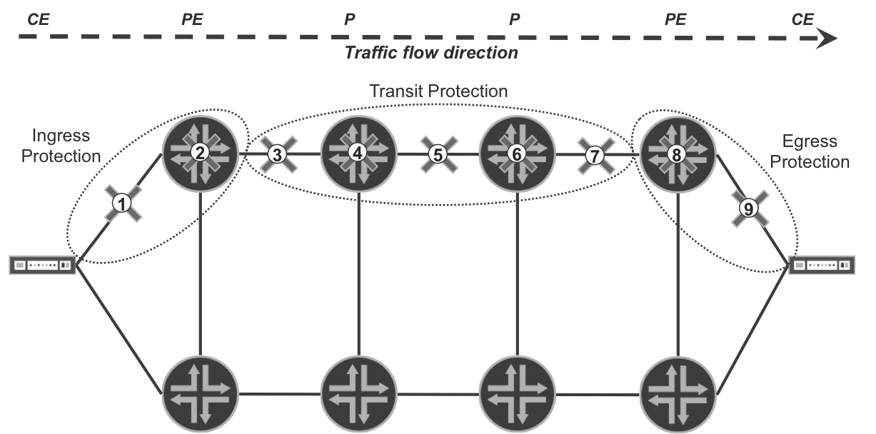
Figure 18-1. Traffic protection classification
Ingress protection isn’t typically MPLS-related; instead, it is based purely on the capabilities of some Layer 3 (L3) PE-CE protocols (e.g., BGP, OSPF, RIP, or VRRP) for L3 services, or Layer 2 (L2) protocols (LACP, some variants of Spanning Tree Protocol [STP], or OAM) for L2 services. Thus, ingress protection is not covered in this book.
Techniques that you can deploy for transit protection (LFA, MRT, RSVP-TE protection) are discussed later in this chapter and in Chapter 19, whereas techniques for egress protection are discussed in Chapter 21. Additionally, Chapter 20 covers optimization in FIB data structures allowing for faster FIB reprogramming.
Global Repair Concepts
During network failure events, the following course of actions leads to traffic redirection over a new path, which can avoid a failed link or node:
-
Failure detection
-
Time required to detect the failure
-
Various techniques are available, depending on the underlying physical transport technology
-
-
New state propagation (flooding)
-
Time required to propagate the information about failed link or node through the network
-
Typically involves IGP (IS-IS or OSPF) flooding
-
This time greatly depends on the size of the network, link distances, and so on.
-
-
Routing database update and new path (and label) computation
-
Time required to compute new paths (next hops)
-
Depends on the IGP database size
-
On modern, high-end routers, this can be approximated with around 1 μs per node (in a network with 1,000 nodes it takes approximately 1 ms to perform Shortest-Path First [SPF] calculation)
-
-
New next-hops (and labels) installation in Hardware Forwarding Information Base (HW FIB)
-
Time required to program HW FIB in the line cards with newly calculated next-hops (labels)
-
Very hardware dependent
-
Can take a relatively long time (measured in seconds) for large number of next hops in a scaled environment
-
By optimizing global convergence parameters, you can achieve subsecond convergence. However, to achieve sub-100 ms convergence, global (network-wide) convergence is no longer enough, because the state propagation, routing database update, new path calculation, and installation of new next hops in HW FIB cannot really be squeezed below a couple of 100 ms. Thus, for very demanding applications that require sub-100 ms traffic failover times during network failures, tuning global convergence parameters alone is no longer enough. In these cases, local repair comes into the picture.
Local Repair Concepts
The idea underpinning local repair is to skip most of the steps that must happen with global repair when a network failure happens. If another next hop was already installed in HW FIB, the only action that needs to be performed during failure events is to detect the failure itself and remove the next hops associated with the failed link or node from the HW FIB. All the other steps are no longer required for local repair. Strictly speaking, local repair is a complement (and not an alternative) to global repair. Indeed, local repair and global repair take place in parallel. Local repair quickly restores data forwarding by using a temporary path while global repair computes the final converged path. As its name implies, local repair is typically a local decision at the PLR and is not negotiated. Rather than on interoperability, we focus on implementation differences.
The most challenging issue with local repair is how to determine potential backup next hops. This chapter and Chapter 19 outline different local-repair techniques that you can deploy in an IP/MPLS network to protect the traffic against transit link or transit node failures, with the goal of providing sub-50 ms traffic restoration times.
Warning
In Junos, ensure that load-balance per-packet is applied, as discussed in Chapter 2. This is necessary to enable local-repair next-hop structures.
Loop-Free Alternates
The local-repair mechanism using Loop-Free Alternates (LFAs) technique is described in the following RFCs:
-
RFC 5714 - IP Fast Reroute Framework
-
RFC 5715 - A Framework for Loop-Free Convergence
-
RFC 5286 - Basic Specification for IP Fast Reroute: Loop-Free Alternates
-
RFC 6571 - Loop-Free Alternate (LFA) Applicability in SP Networks
LFA techniques require link-state IGP protocols such as IS-IS or OSPF. When LFA is deployed, in addition to standard SPF calculation, routers perform the SPF calculation from the perspective of each directly connected IGP neighbor. For example, in the topology illustrated in Figure 18-2 (which is a variant of the intradomain topology used in Chapter 16), router PE4, acting as a potential (future) PLR, performs five SPF calculations:
-
One primary SPF calculation, using the local node (PE4) as the root of the SPF tree. Routers always perform this type of SPF calculations, regardless of whether LFA is enabled, to determine primary next hops due to normal IGP operation.
-
Four backup SPF calculations, with each calculation using a different direct IGP neighbor node (P2, P5, P6, or PE3) as the root of the SPF tree. Routers perform this type of SPF calculation to determine backup next-hops only if the LFA feature is enabled.
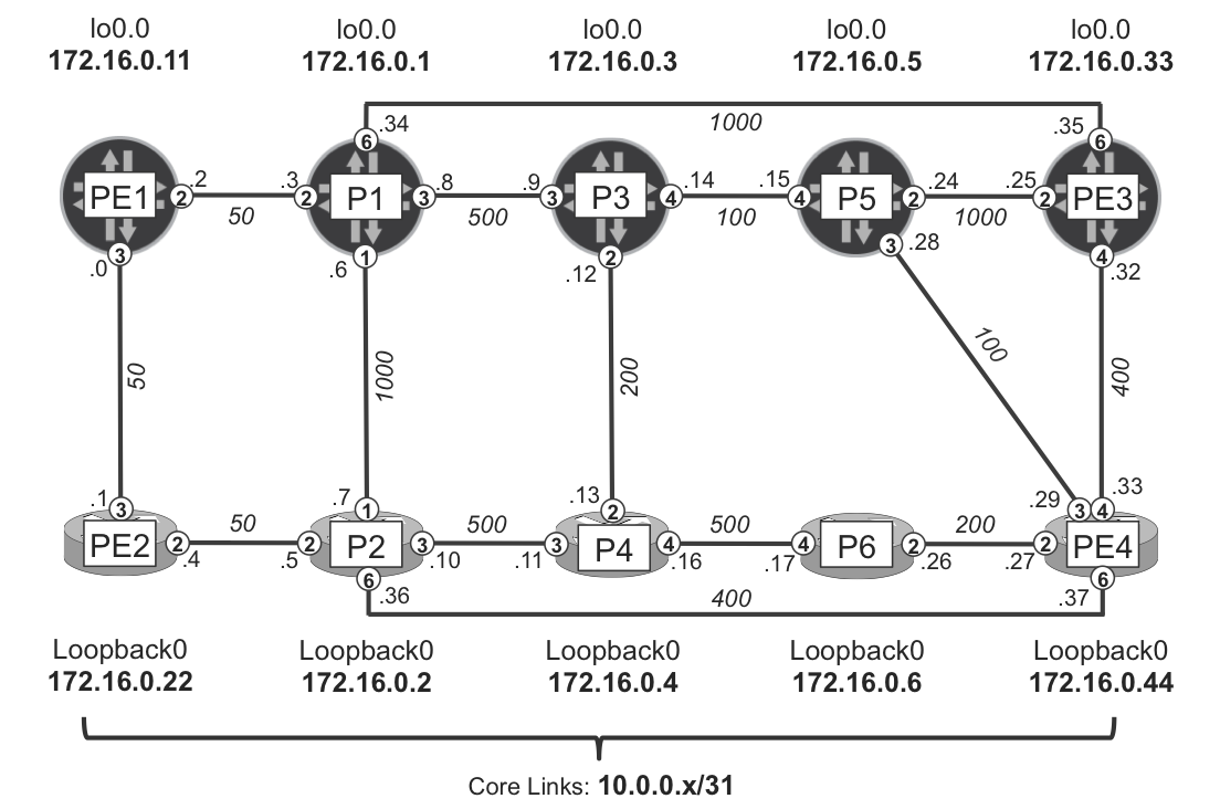
Figure 18-2. LFA topology A
The backup next hop is considered loop-free if the result of a backup SPF calculation does not point back to the node which performs the local repair. In other words, the following condition is checked to determine if the backup next hop is loop-free:
Distance(N, D) < Distance(N, S) + Distance(S, D)
where:
-
S= router performing the local repair -
D= destination under consideration -
N= neighbor node that can be used as a potential backup next hop
Note
For simplicity, and like in other examples of this book, IGP metrics are symmetrically configured, so for any two routers R1 and R2, the R1→R2 and the R2→R1 link metrics are the same.
In the example topology, P2 is the primary next hop to reach P1 from PE4. To verify whether P6 is a feasible backup next hop, you need to test for the following condition:
Distance(P6, P1) < Distance(P6, PE4) + Distance(PE4, P1)
750 (P6→PE4→P2→PE2→PE1→P1) < 200 + 550 (PE4→P2→PE2→PE1→P1)
750 < 750 (false)
So, P6 cannot be used as backup next hop, because the shortest path to reach P1 from P6 is actually via PE4. When evaluating whether P5 is a feasible backup next hop, you’ll get the following:
Distance(P5, P1) < Distance(P5, PE4) + Distance(PE4, P1)
600 (P5→P3→P1) < 100 + 550 (PE4→P5→P3→P1)
600 < 650 (true)
This makes P5 suitable as a potential backup loop-free next hop for PE4 to reach P1 because the shortest path from P5 to P1 does not traverse PE4.
Only loop-free backup next hops can be installed in the FIB and used as a real backup to forward the traffic during network failures.
There are two types of LFA:
- Per-link
- All prefixes originally reachable over a failed link use the same backup next hop. This type of protection is sometimes also called Per-Next-Hop LFA.
- Per-prefix
- Prefixes originally reachable over a failed link or node may use a different backup next hop on a per-prefix basis.
The next sections of this chapter describe both of these LFA flavors in more detail.
Per-Link LFA
Example 18-1 shows an IOS XR configuration to enable per-link LFA for all IS-IS enabled interfaces. You can simply enhance the existing configuration group (GR-ISIS) used to parameterize ISIS interface configuration.
Example 18-1. Per-Link LFA configuration (IOS XR)
group GR-ISIS
 router isis '.*'
  interface 'GigabitEthernet.*'
   address-family ipv4 unicast
    fast-reroute per-link
end-group
router isis core
 apply-group GR-ISIS
The first thing to look at is the LFA summary overview, which shows you the backup coverage percentage.
Example 18-2. Backup coverage with per-link LFA on PE4 (IOS XR)
RP/0/0/CPU0:PE4#show isis fast-reroute summary
(...)
                            High       Medium     Low        Total
                            Priority   Priority   Priority
Prefixes reachable in L2
  All paths protected       0          0          0          0
  Some paths protected      0          0          0          0
  Unprotected               0          9          15         24
  Protection coverage       0.00%      0.00%      0.00%      0.00%
You can see that there are nine medium-priority (loopbacks) and 15 low-priority (links) prefixes for which LFA protection is desired. Based on the topology from Figure 18-2, those numbers are expected. There are 10 loopbacks altogether in the topology but the local loopback is visible only as a directly connected route (not as an IS-IS route). Table 18-1 summarizes the backup coverage results for loopbacks observed on all routers in the topology. On the Junos routers in this topology, LFA is not currently configured; thus, LFA coverage on the Junos plane is not yet available.
| P1 | P2 | P3 | P4 | P5 | P6 | PE1 | PE2 | PE3 | PE4 |
|---|---|---|---|---|---|---|---|---|---|
| n/a | 9 | n/a | 9 | n/a | 9 | n/a | 0 | n/a | 0 |
| n/a | 100% | n/a | 100% | n/a | 100% | n/a | 0% | n/a | 0% |
Interestingly, for some of the routers, backup coverage is 100%. However, there are some routers for which it seems the LFA is not functioning, because all prefixes are unprotected. Let’s have a closer look at one such router (for example, PE4), focusing on the paths toward loopback prefixes.
Example 18-3. Routing table on PE4 (IOS XR)
RP/0/0/CPU0:PE4#show route isis | begin /32
i L2 172.16.0.1/32 [115/550] via 10.0.0.36, 00:06:25, Gi0/0/0/6
i L2 172.16.0.2/32 [115/400] via 10.0.0.36, 00:13:02, Gi0/0/0/6
i L2 172.16.0.3/32 [115/200] via 10.0.0.28, 00:13:00, Gi0/0/0/3
i L2 172.16.0.4/32 [115/400] via 10.0.0.28, 00:06:25, Gi0/0/0/3
i L2 172.16.0.5/32 [115/100] via 10.0.0.28, 00:13:00, Gi0/0/0/3
i L2 172.16.0.6/32 [115/200] via 10.0.0.26, 00:13:00, Gi0/0/0/2
i L2 172.16.0.11/32 [115/500] via 10.0.0.36, 00:13:02, Gi0/0/0/6
i L2 172.16.0.22/32 [115/450] via 10.0.0.36, 00:13:02, Gi0/0/0/6
i L2 172.16.0.33/32 [115/400] via 10.0.0.32, 00:13:00, Gi0/0/0/4
We can summarize the information from PE4’s routing table as such:
-
The P6 (172.16.0.6) loopback is reachable via Gi0/0/0/2.
-
The PE3 (172.16.0.33) loopback is reachable via Gi0/0/0/4.
-
P3, P4, and P5 loopbacks are reachable via Gi0/0/0/3.
-
All other loopbacks are reachable via Gi0/0/0/6.
So, if you look carefully at the link metrics, no loop-free backup next hop can be found for most of the loopbacks. Based on the link metrics deployed in the network, all backup SPF calculations for most of the loopbacks will result in the next hop pointing back to PE4. Consequently, these loopbacks do not have LFA backup coverage in this topology. But there are some exceptions; for example, the loopback of P1.
Remember that P5 is a loop-free backup for PE4 to reach P1:
Distance(P5, P1) < Distance(P5, PE4) + Distance(PE4, P1)
If a feasible backup next hop exists, why is it not used? The answer lies with per-link LFA. As already mentioned, all prefixes originally reachable over a failed link must use the same loop-free backup next hop in per-link LFA. And in this example, this is not the case. For P1 (reachable via Gi0/0/0/6 interface), a loop-free backup next hop exists (P5), but for P2, which is normally reachable via Gi0/0/0/6, too, it does not. As a result, in case of Gi0/0/0/6 failure, all traffic that originally used Gi0/0/0/6 (P2) as a next hop cannot be redirected over Gi0/0/0/3 (P5), because it would loop for some of the flows—flows destined for P2, for example, given that the shortest path from P5 to P2 is via PE4. Thus, the per-link (per-next-hop) LFA does not install any backup next-hops if the common backup next-hop cannot be used for each and every prefix originally reachable over the failed link.
On some other routers, it is better. LFA backup coverage on P2, P4, or P6 is 100%. This means that all IS-IS prefixes are covered by the LFA backup feature. Let’s verify the content of the routing table on P4, as well (see Example 18-4).
Example 18-4. Routing table on P4 (IOS XR)
RP/0/0/CPU0:P4#show route isis | begin /32
i L2 172.16.0.1/32 [115/650] via 10.0.0.10, 15:24:38, Gi0/0/0/3
                   [115/0] via 10.0.0.12, 15:24:38, Gig0/0/0/2 (!)
i L2 172.16.0.2/32 [115/500] via 10.0.0.10, 02:06:54, Gi0/0/0/3
                   [115/0] via 10.0.0.12, 02:06:54, Gi0/0/0/2 (!)
i L2 172.16.0.3/32 [115/0] via 10.0.0.17, 17:52:11, Gig0/0/0/4 (!)
                   [115/200] via 10.0.0.12, 17:52:11, Gi0/0/0/2
i L2 172.16.0.5/32 [115/0] via 10.0.0.17, 17:52:11, Gi0/0/0/4 (!)
                   [115/300] via 10.0.0.12, 17:52:11, Gi0/0/0/2
i L2 172.16.0.6/32 [115/500] via 10.0.0.17, 17:45:13, Gi0/0/0/4
                   [115/0] via 10.0.0.12, 17:45:13, Gi0/0/0/2 (!)
i L2 172.16.0.11/32 [115/600] via 10.0.0.10, 15:24:38, Gi0/0/0/3
                    [115/0] via 10.0.0.12, 15:24:38, Gi0/0/0/2 (!)
i L2 172.16.0.22/32 [115/550] via 10.0.0.10, 15:24:38, Gi0/0/0/3
                    [115/0] via 10.0.0.12, 15:24:38, Gi0/0/0/2 (!)
i L2 172.16.0.33/32 [115/0] via 10.0.0.17, 17:50:38, Gi0/0/0/4 (!)
                    [115/800] via 10.0.0.12, 17:50:38, Gi0/0/0/2
i L2 172.16.0.44/32 [115/0] via 10.0.0.17, 17:52:11, Gi0/0/0/4 (!)
                    [115/400] via 10.0.0.12, 17:52:11, Gi0/0/0/2
When you compare it to the previous case (Example 18-3), you can see that there are two next hops for each prefix. In each case, one of the next hops is marked with a mysterious (!). A more detailed view of one of the prefixes, shown in the following example, sheds more light on what is actually happening here:
Example 18-5. Detailed RIB entry with per-link LFA backup on P4 (IOS XR)
1     RP/0/0/CPU0:P4#show route 172.16.0.33/32 detail | include <pattern>
2     Known via "isis core", distance 115, metric 800, type level-2
3       10.0.0.12, from 172.16.0.33, via GigabitEthernet0/0/0/2, Protected
4         Route metric is 800
5         Path id:1       Path ref count:0
6         Backup path id:33
7       10.0.0.17, from 172.16.0.33, via GigabitEthernet0/0/0/4, Backup
8         Route metric is 0
9         Path id:33              Path ref count:1
The primary path (via Gi0/0/0/2) is marked with a Protected tag. This indicates that there must be some backup path, which protects the primary path. Additionally, the primary path contains information about the backup path (line 6), which is expanded in lines 7 through 9. In this particular case, the backup path is via Gi0/0/0/4.
If you look back at the output in Example 18-4, you should see that the primary next-hop and the backup next-hop correlation are always consistent. For example, the Gi0/0/0/2 primary next hop is coupled together with the Gi0/0/0/4 backup next hop for all prefixes that use Gi0/0/0/2 as the primary next hop. This is actually the main characteristic of per-link LFA: failure of the primary link causes redirection of all traffic originally flowing via this link over a single backup link. If a single backup link that satisfies loop-free criteria cannot be found, the backup next hop is not used at all, as we saw with PE4.
This characteristic of per-link LFA makes it very inefficient in providing high backup coverage in most real deployments. Thus, many router vendors do not implement per-link LFA in their products as more advanced LFA variants provide much better backup coverage. Additionally, per-link LFA does not provide protection against node failure (just link failure), which further reduces its usability. As of this writing, per-link LFA is available in IOS XR but not in Junos or IOS.
In addition to Routing Information Base (RIB) structures investigated previously, let’s also have a look at the Forwarding Information Base (FIB) structure.
Example 18-6. IP FIB entry with LFA backup on P4 (IOS XR)
RP/0/0/CPU0:P4#show cef 172.16.0.33/32
(...)
 Prefix Len 32, traffic index 0, precedence n/a, priority 3
   via 10.0.0.12, Gi0/0/0/2, 6 dependencies, weight 0, protected
    path-idx 0 bkup-idx 1 NHID 0x0 [0xa14d6d7c 0x0]
    next hop 10.0.0.12
     local label 24005      labels imposed {300400}
   via 10.0.0.17, Gi0/0/0/4, 6 dependencies, weight 0, backup
    path-idx 1 NHID 0x0 [0xa107024c 0x0]
    next hop 10.0.0.17
    local adjacency
     local label 24005      labels imposed {24001}
You can see that both the primary and backup next hops use some MPLS labels. In this example topology, the label is exchanged via LDP, as shown in Figure 18-3. The mechanism works fine too if you use SPRING instead of LDP.
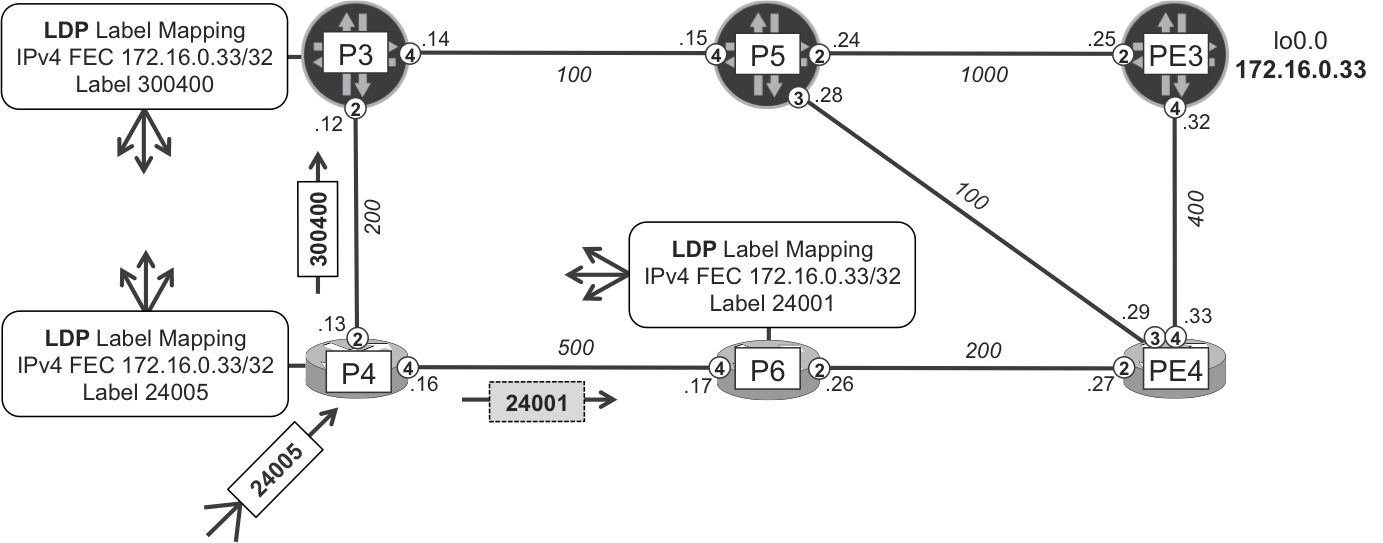
Figure 18-3. Link LFA protecting traffic from P4 to PE3
Label values are different, because P4 receives FECs over different LDP sessions. For the primary and backup next hop, P4 receives the label from P3 and P6, respectively.
The backup next hop is installed not only in the IP FIB, but also in the MPLS FIB (the LFIB). Example 18-7 shows a MPLS FIB entry for the label assigned by P4 to PE3 loopback. The entry is very similar to the IP FIB entry for PE3 loopback discussed previously.
Example 18-7. MPLS FIB entry with LFA backup on P4 (IOS XR)
RP/0/0/CPU0:P4#show cef mpls local-label 24005 EOS
(...)
 Prefix Len 21, traffic index 0, precedence n/a, priority 3
   via 40960/0, Gi0/0/0/2, 6 dependencies, weight 0, protected
    path-idx 0 bkup-idx 1 NHID 0x0 [0xa14d6d7c 0x0]
    next hop 10.0.0.12
     local label 24005      labels imposed {300400}
   via 40960/0, Gi0/0/0/4, 6 dependencies, weight 0, backup
    path-idx 1 NHID 0x0 [0xa107024c 0x0]
    next hop 10.0.0.17
    local adjacency
     local label 24005      labels imposed {24001}
Now, when the primary interface (Gi0/0/0/2) fails, P5 (depending on how quickly the failure is discovered) removes the primary next hop from FIB structures. Before global convergence completes, traffic can be forwarded based on the backup next hop preprogrammed in the FIB. After global convergence finishes, a new set of primary and backup (if a loop-free backup is found) next hops will be installed in the FIB, overriding the old backup next hop used for temporal traffic forwarding.
Per-Prefix LFA
Per-prefix LFA increases the backup coverage because it allows for different per-prefix backup next hops. Both Junos and IOS XR support it.
Per-prefix LFA in IOS XR
Recall from the discussion about per-link LFA on PE4 that the problem was because different prefixes required different backup next hops. Thus, per-link LFA was not working there. Let’s now replace per-link LFA with the per-prefix LFA configuration presented in Example 18-8 and again verify the backup coverage.
Example 18-8. Per-prefix LFA configuration (IOS XR)
group GR-ISIS
 router isis '.*'
  interface 'GigabitEthernet.*'
   address-family ipv4 unicast
    fast-reroute per-prefix
On two IOS XR routers, there was no backup coverage when per-link LFA was used, but you can now see some increase. Table 18-2 shows that the backup coverage for PE4 in particular has jumped from 0% (with per-link LFA) to 22.2% (with per-prefix LFA).
| P1 | P2 | P3 | P4 | P5 | P6 | PE1 | PE2 | PE3 | PE4 |
|---|---|---|---|---|---|---|---|---|---|
| n/a | 9 | n/a | 9 | n/a | 9 | n/a | 1 | n/a | 2 |
| n/a | 100% | n/a | 100% | n/a | 100% | n/a | 11.1% | n/a | 22.2% |
Let’s determine which prefixes are actually protected on PE4.
Example 18-9. Prefix-specific LFA information on PE4 (IOS XR)
1     RP/0/0/CPU0:PE4#show isis fast-reroute detail | begin "/32"
2     L2 172.16.0.1/32 [550/115] medium priority
3          via 10.0.0.36, Gi0/0/0/6, P2, Weight: 0
4            FRR backup via 10.0.0.28, Gi0/0/0/3, P5, Weight: 0
5            P: No, TM: 700, LC: No, NP: Yes, D: No, SRLG: Yes
6          src P1.00-00, 172.16.0.1
7     (...)
8     L2 172.16.0.4/32 [400/115] medium priority
9          via 10.0.0.28, Gi0/0/0/3, P5, Weight: 0
10           FRR backup via 10.0.0.26, Gi0/0/0/2, P6, Weight: 0
11           P: No, TM: 700, LC: No, NP: Yes, D: No, SRLG: Yes
12         src P4.00-00, 172.16.0.4
13    (...)
Now, thanks to the per-prefix LFA feature, you can use the loop-free backup next hops on a per-prefix basis and install them in the FIB. However, there are still some prefixes without a loop-free backup next hop.
Using show command outputs, you can observe the total metric (TM) of the path through the primary next hop (line 2: 550, and line 8: 400) as well as through the backup next hop (line 5: 700, and line 11: 700). Additionally, you get an indication whenever the backup path fulfills node protection (the backup path avoids the neighbor node used as primary next hop) criterion (line 5 and 11: NP: Yes).
Looking at the backup next hop for another prefix on another router (Example 18-10), you can see slightly different flag values.
Example 18-10. Prefix-specific LFA information on P2 (IOS XR)
RP/0/0/CPU0:P2#show isis fast-reroute 172.16.0.33/32 detail
L2 172.16.0.33/32 [800/115] medium priority
     via 10.0.0.37, Gi0/0/0/6, PE4, Weight: 0
       FRR backup via 10.0.0.11, Gi0/0/0/3, P4, Weight: 0
       P: No, TM: 1300, LC: No, NP: No, D: No, SRLG: Yes
     src PE3.00-00, 172.16.0.33
So, what is the difference between the backup next hops observed in these previous two examples? If you go back to the topology (Figure 18-2), you should see that in Example 18-9 the backup next hop for the P1 loopback provides protection against primary link (PE4→P2) and primary node (P2) failures. Packets redirected to the backup next hop will reach their final destination without transiting P2. In Example 18-10, however, this is not the case. The packets from P2 destined to PE3 and redirected over the backup next hop (P4) will transit the primary next hop (PE4), because the backup path is P2→P4→P3→P5→PE4→PE3. Thus, this backup path provides protection only against primary link failure, not against primary node failure. We’ll discuss the other visible flags later, but let’s have a look at a few Junos devices first.
Per-prefix LFA in Junos
Let’s now enable per-prefix LFA on our Junos devices. Whereas in IOS XR you didn’t need to specify what kind of LFA backup next hops are permitted, Junos offers two configuration options:
node-link-protection- Installs, if possible, loop-free backup next hops, which fulfill both node protection (backup path avoids neighbor node used as primary next hop) and link protection (backup path avoids original link used to reach primary next hop) criteria.
link-protection- Installs, if possible, loop-free backup next hops, which fulfill at least the link protection (backup path avoids original link used to reach primary next hop) criterion. Node protection criterion (backup path avoids neighbor node used as primary next hop) might be fulfilled as well, but is not verified or enforced.
OK, so you have choices. The first choice looks more promising (protection against both node and link failures), so let’s try it first.
Example 18-11. Per-prefix node-link-protection LFA configuration (Junos)
groups {
    GR-ISIS {
        protocols {
            isis {
                interface "<*[es]*>" {   # Matches Ethernet and SONET
                    node-link-protection;
}}}}}
protocols {
    isis {
        apply-groups GR-ISIS;
}}
Note
If you come from the RSVP-TE world, you will find it surprising the way that [node-]link-protection is interpreted for LFA. This point is discussed in greater detail in Chapter 19.
And again, the first thing you probably want to know is the LFA backup coverage you can achieve. The following example reveals this for you:
Example 18-12. Backup coverage with per-prefix node-link-protection LFA on P5 (Junos)
juniper@P5> show isis backup coverage
Backup Coverage:
Topology        Level   Node    IPv4    IPv6    CLNS
IPV4 Unicast        2  55.56%  65.00%   0.00%   0.00%
The backup coverage is 55.56% for nodes, and 65.00% for IPv4 prefixes. Because you have a single loopback per node, it basically means five loopback prefixes—out of nine—have LFA backup coverage, whereas four do not. The next column shows backup coverage for all IS-IS prefixes (loopback prefixes + link prefixes). Table 18-3 summarizes LFA backup coverage for loopbacks on all routers with the current LFA feature set enabled.
| P1 | P2 | P3 | P4 | P5 | P6 | PE1 | PE2 | PE3 | PE4 |
|---|---|---|---|---|---|---|---|---|---|
| 9 | 9 | 8 | 9 | 5 | 9 | 1 | 1 | 8 | 2 |
| 100% | 100% | 88.9% | 100% | 55.6% | 100% | 11.1% | 11.1% | 88.9% | 22.2% |
Out of ten routers, only four provide 100% backup coverage. Some of the routers provide backup coverage for a single loopback only. Let’s look for destination nodes with no LFA backup next hop from P5.
Example 18-13. Node-specific LFA information on P5 (Junos)
1     juniper@P5> show isis backup spf results no-coverage | except item
2     (...)
3     P2.00
4       Primary next-hop: ge-2/0/3.0, IPV4, PE4, SNPA:  0:50:56:8b:4e:c8
5         Root: PE4, Root Metric: 100, Metric: 400, Root Preference: 0x0
6           Not eligible, IPV4, Reason: Primary next-hop link fate sharing
7         Root: P3, Root Metric: 100, Metric: 600, Root Preference: 0x0
8           Not eligible, IPV4, Reason: Path loops
9         Root: PE3, Root Metric: 500, Metric: 800, Root Preference: 0x0
10          Not eligible, IPV4, Reason: Primary next-hop node fate sharing
11    (...)
12      4 nodes
There is a lot of information here. The no-coverage keyword was used in the show output; thus, only backup SPF results for destination nodes with no backup coverage from P5 are displayed. They are P2 (lines 3 through 10), as well as P3, P4, and P6 (not listed for brevity). The primary next hop for P2 is PE4 via ge-2/0/3.0 interface (line 4).
For each destination node (in this example, P2), you can see the list of P5’s neighbors. These neighbors are evaluated for potential backup next-hop function to reach P2 and thus used as the root of the SPF tree during backup SPF calculations. For every such neighbor, two metrics are displayed. For example, in line 5, Root Metric (100) is the metric from the PLR (P5) to the neighbor (PE4), and Metric (400) is the metric from the neighbor (PE4) to the destination (P2).
P5 cannot use the primary next hop node (PE4) as a backup next hop (lines 5 and 6), because it is already the primary next-hop node, and there is only a single direct link to the node; therefore, no other link could be used as backup. This is obvious.
P5 cannot use the P3 node as a backup next hop due to a loop (lines 7 and 8). The shortest path from P3 to P2 is via P5 (P3→P5→PE4→P2), so traffic eventually redirected to P3 would come back to P5.
Finally, P5 cannot use the PE3 node due to primary next-hop node fate sharing. What does that mean? It means that the shortest path from PE3 to P2 is via the primary next hop PE4 (PE3→PE4→P2); hence, the backup path from P5 to P2 via PE3 (and then via PE4) does not fulfill node protection criterion. Because with node-link-protection this criterion is verified and enforced, PE3 cannot be used as backup next hop. Similar analysis can be done for other nodes with no backup coverage.
Before implementing some enhancements in LFA to extend backup coverage, let’s explore the Junos RIB and FIB structures (see Example 18-14), similar to what we did for IOS XR in Example 18-6 and Example 18-7.
Example 18-14. Routing table on P5 (Junos)
1     juniper@P5> show route protocol isis table inet.0 | find "/32"
2     172.16.0.1/32      *[IS-IS/18] 03:39:20, metric 600
3                         > to 10.0.0.14 via ge-2/0/4.0
4                           to 10.0.0.29 via ge-2/0/3.0
5     172.16.0.2/32      *[IS-IS/18] 00:23:49, metric 500
6                         > to 10.0.0.29 via ge-2/0/3.0
7     172.16.0.3/32      *[IS-IS/18] 03:39:20, metric 100
8                         > to 10.0.0.14 via ge-2/0/4.0
9     172.16.0.4/32      *[IS-IS/18] 03:39:20, metric 300
10                        > to 10.0.0.14 via ge-2/0/4.0
11    172.16.0.6/32      *[IS-IS/18] 00:23:49, metric 300
12                        > to 10.0.0.29 via ge-2/0/3.0
13    172.16.0.11/32     *[IS-IS/18] 03:39:20, metric 600
14                        > to 10.0.0.29 via ge-2/0/3.0
15                          to 10.0.0.14 via ge-2/0/4.0
16    172.16.0.22/32     *[IS-IS/18] 03:39:20, metric 550
17                        > to 10.0.0.29 via ge-2/0/3.0
18                          to 10.0.0.14 via ge-2/0/4.0
19    172.16.0.33/32     *[IS-IS/18] 03:39:20, metric 500
20                        > to 10.0.0.29 via ge-2/0/3.0
21                          to 10.0.0.25 via ge-2/0/2.0
22    172.16.0.44/32     *[IS-IS/18] 03:39:20, metric 100
23                        > to 10.0.0.29 via ge-2/0/3.0
24                          to 10.0.0.25 via ge-2/0/2.0
Some of the prefixes have only a single next hop, whereas some other prefixes—apparently covered by LFA backup—have two next hops. This is to be expected, because for these prefixes, LFA backup next hop is determined and installed. Furthermore the backup next hop for prefixes using the same primary next hop might be different (lines 17 and 18, versus 20 and 21). This confirms that the Junos implementation uses per-prefix (and not per-link) LFA style. Let’s see the available next hops to reach PE2 from P5, by matching Figure 18-4 (IPv4 FECs are signaled with LDP) to Example 18-15.
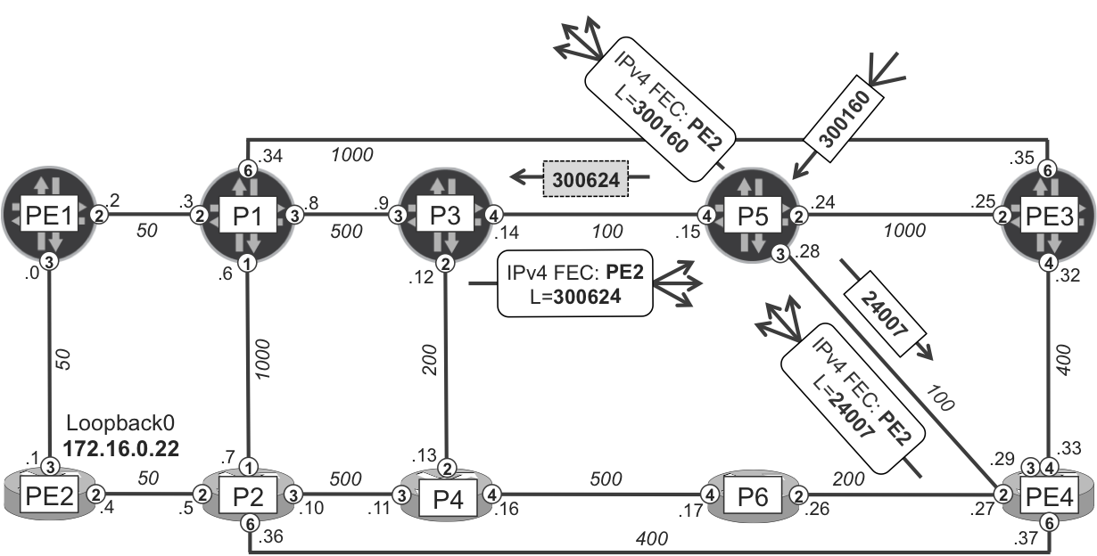
Figure 18-4. Per-prefix LFA protecting traffic from P5 to PE2
Example 18-15. IP/MPLS RIB/FIB entries with LFA backup on P5 (Junos)
juniper@P5> show route protocol isis table inet.0 172.16.0.22/32
            detail | match "Prefer|via|Metric"
 *IS-IS  Preference: 18
         Next hop: 10.0.0.29 via ge-2/0/3.0 weight 0x1, selected
         Next hop: 10.0.0.14 via ge-2/0/4.0 weight 0xf000
         Age: 3:42:33    Metric: 550

juniper@P5> show route label 300160 detail | match <pattern>
 *LDP    Preference: 9
         Next hop: 10.0.0.29 via ge-2/0/3.0 weight 0x1, selected
         Label operation: Swap 24007
         Next hop: 10.0.0.14 via ge-2/0/4.0 weight 0xf000
         Label operation: Swap 300624
         Age: 3:45:50    Metric: 550

juniper@P5> show route forwarding-table table default destination
            172.16.0.22/32 extensive | match <pattern>
Destination:  172.16.0.22/32
  Next-hop interface: ge-2/0/3.0    Weight: 0x1
  Next-hop interface: ge-2/0/4.0    Weight: 0xf000

juniper@P5> show route forwarding-table table default label 300160
            extensive | match "Dest|interface:|Weight|type"
Destination:  300160
  Next-hop type: Swap 24007          Index: 606   Reference: 1
  Next-hop interface: ge-2/0/3.0    Weight: 0x1
  Next-hop type: Swap 300624         Index: 590   Reference: 1
  Next-hop interface: ge-2/0/4.0    Weight: 0xf000
You can see that P3 is a valid backup next hop, because its shortest path to the destination is P3→P1→PE1→PE2 (metric 600), which does not go through P5.
The IP RIB/FIB as well as the MPLS RIB/FIB entries (label 300160 is locally assigned to prefix 172.16.0.22/32) contain two next hops. The primary next hop has a weight 0x1, whereas the backup next hop has a weight 0xf000. In Junos, only next hops with the numerically lowest value are actively used for traffic forwarding. If more next hops have the same (low) value, load-balancing between next hops is performed. Next hops with higher weight values are true backup next hops only. They are installed in the FIB but are not used for traffic forwarding in the absence of failures. When some failure happens, and the primary next hop is removed from the FIB, the backup next hop is used. And again, if multiple backup next hops exist, the backup next hop (or next hops) with the lowest weight value will be used for traffic forwarding.
As observed on P5 (Example 18-13), node and link protection strategy caused some inefficiency in terms of backup coverage. So let’s try using only link protection and verify backup coverage.
Example 18-16. Per-prefix link-protection LFA configuration (Junos)
groups {
    GR-ISIS {
        protocols {
            isis {
                interface "<*[es]*>" {
                    link-protection;
}}}}
Table 18-4 shows that on two nodes, backup LFA coverage increased: P5 (from 5 to 7) and PE3 (from 8 to 9). So, the design becomes better and better, but still only five nodes have LFA backup next hops for all loopback prefixes.
| P1 | P2 | P3 | P4 | P5 | P6 | PE1 | PE2 | PE3 | PE4 |
|---|---|---|---|---|---|---|---|---|---|
| 9 | 9 | 8 | 9 | 7 | 9 | 1 | 1 | 9 | 2 |
| 100% | 100% | 88.9% | 100% | 77.8% | 100% | 11.1% | 11.1% | 100% | 22.2% |
Looking back at Example 18-13, it’s clear that sometimes backup next hops were rejected due to potential loops. Changing from node and link protection style to link protection style doesn’t help in this example, unfortunately, as potential loops remain. You need to deploy some more advanced LFA features to overcome this topology limitation.
But going back to link protection style, when configuring per-prefix link-protection LFA, it seems that you can increase the backup coverage. So, the legitimate question is: What benefits can node-link protection bring? Apart from providing a backup path that can protect against primary link and node failure, are there other benefits?
Let’s check the forwarding state toward P2 loopback (172.16.0.2/32) on P5 and PE3, when the P1-P3 and P3-P4 links are temporarily disabled in order to slightly change the network topology (or, to simulate multiple failures in the network). The following two examples and Figure 18-5 assume that link (not node-link) protection is configured.
Example 18-17. FIB entry toward P2 loopback on P5 (Junos)
juniper@P5> show route forwarding-table table default
            destination 172.16.0.2/32
(...)
Destination    Type RtRef Next hop        Type Index    NhRef Netif
172.16.0.2/32  user     1                 ulst  1048596    15
                          10.0.0.29   ucst      586    29 ge-2/0/3.0
                          10.0.0.25   ucst      581    23 ge-2/0/2.0
Example 18-18. FIB entry toward P2 loopback on PE3 (Junos)
juniper@PE3> show route forwarding-table table default
             destination 172.16.0.2/32
Routing table: default.inet
Internet:
Destination    Type RtRef Next hop    Type Index    NhRef Netif
172.16.0.2/32  user     0             ulst  1048585    24
                          10.0.0.33   ucst      595    25 ge-2/0/4.0
                          10.0.0.24   ucst      542    26 ge-2/0/2.0
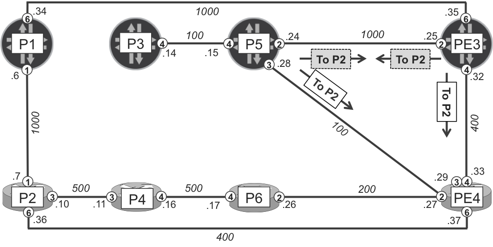
Figure 18-5. Per-prefix link-protection LFA protecting traffic from P5 and PE3 to P2 (potential microloop)
Both P5 and PE3 point to PE4 as the primary next hop. And both P5 and PE3 point to each other as backup next hops. Now, imagine PE4 fails. As discussed already, before global convergence happens, the primary next hop is removed and forwarding is based on the backup next hop. As a result, the FIB entry for 172.16.0.2/32 has the following next hops:
-
At P5’s FIB, the next hop is 10.0.0.25 (ge-2/0/2.0). In other words, PE3.
-
At PE3’s FIB, the next hop is 10.0.0.24 (ge-2/0/2.0). In other words, P5.
This is a loop! Both P5 and PE3 have only a single next hop, and they are pointing to each other. Until global convergence happens, which replaces old next hops with newly calculated next hops, there is indeed a loop. You may well ask how is this possible? The technology under discussion is called Loop-Free Alternates.
This kind of loop in LFA is called a microloop. In this particular case, LFA backup next hop protects only against a single P5-PE4 link failure, but not against PE4’s node failure. For single link failure, LFA with link-protection is loop free. However, if the failure is bigger than expected (for example multiple link failures or node failure), then micro-loops might occur if LFA had computed only link-protection backup next hop. This was recognized very early in the LFA development stage (RFC 5286, Section 1.1).
On the other hand, node protection LFA (if available) completely eliminates any chance of micro-loops during multiple link (connected to the same node) failures, at least in those basic LFA deployments where we do not impose any additional path restrictions (like SLRG). Thus, the preferred LFA deployment strategy is to use backup next hops that satisfy node protection criterion (to eliminate microloops), and use backup next hops that satisfy the link protection criterion only as last resort. This logic is implemented by default in IOS XR, whereas in Junos you need to pay extra attention to implement such logic. It is called node-link-degradation.
Example 18-19. Node-link protection with link degradation LFA (Junos)
groups {
    GR-ISIS {
        protocols {
            isis {
                interface "<*[es]*>" {
                    node-link-protection;
}}}}}
protocols {
    isis {
        apply-groups GR-ISIS;
        backup-spf-options node-link-degradation;
}}
LFA backup coverage in Table 18-4 will not change regardless of whether node-link protection with degradation or only link protection is configured. But you gain the benefits of next hops that satisfy node protection requirements (if possible) as well as next hops that otherwise satisfy only link protection requirements. On the other hand, node protection backup paths are typically longer, causing more latency for rerouted traffic during the time the protection is active. However, this typically lasts for a short period of time (few 100 ms up to few seconds in very large networks) until global IGP convergence installs new optimized paths. Before starting the discussion about techniques that can be used to extend LFA backup coverage (remember that in both IOS XR and Junos planes, the LFA backup coverage was still below 100% on some routers), let’s review another difference between default IOS XR and Junos LFA implementations. Let’s temporarily use a slightly different topology, as illustrated in Figure 18-6.
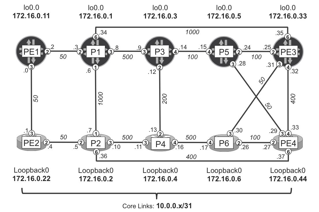
Figure 18-6. LFA topology B
Now, when you check reachability of the PE3-PE4 link prefix on P5 and P6 (see Example 18-20), you will be surprised to find some inconsistency, although P5 and P6 connectivity to PE3 and PE4 is fully symmetrical. In all of the previous cases, loopback prefixes were used to investigate LFA behavior. Loopbacks are injected into the IGP domain by a single router, whereas link prefixes are injected by two routers.
Example 18-20. RIB entry for PE3-PE4 link prefix on P5 and P6
juniper@P5> show route 10.0.0.32/31
(...)
10.0.0.32/31       *[IS-IS/18] 00:03:37, metric 450
                    > to 10.0.0.29 via ge-2/0/3.0

RP/0/0/CPU0:P6#show route isis
(...)
i L2 10.0.0.32/31 [115/450] via 10.0.0.31, 00:03:48, Gi0/0/0/3
                  [115/0] via 10.0.0.27, 00:03:48, Gi0/0/0/2 (!)
(...)
Whereas P6 (IOS XR) has primary and backup next hops, P5 (Junos) has only a primary next hop; the backup next hop is missing. On P5, the primary next-hop is PE4, so let’s see if there is any specific information in the backup SPF results for PE4.
Example 18-21. Backup SPF results for PE4 on P3 (Junos)
juniper@P5> show isis backup spf results PE4 | match <pattern>
  Primary next-hop: ge-2/0/3.0, IPV4, PE4, SNPA:  0:50:56:8b:4e:c8
    Root: PE4, Root Metric: 50, Metric: 0, Root Preference: 0x0
      Not eligible, IPV4, Reason: Primary next-hop link fate sharing
    Root: P3, Root Metric: 100, Metric: 150, Root Preference: 0x0
      Not eligible, IPV4, Reason: Path loops
    Root: PE3, Root Metric: 100, Metric: 150, Root Preference: 0x0
      Not eligible, IPV4, Reason: Path loops
Neither of P5’s neighbors is eligible to be the backup next hop toward PE4. Why is PE3 not considered as a backup next hop? From the perspective of P5, the 10.0.0.32/31 prefix has PE4 as its best originator, therefore that prefix somehow belongs to PE4. Looking at the topology and link metrics, all of P5’s neighbors will forward traffic destined for the PE4 node back via P5, causing a loop. So, what is the difference on P6? Let’s see.
Example 18-22. Backup SPF results for PE4 on P6 (IOS XR)
RP/0/0/CPU0:P6#show isis fast-reroute 10.0.0.32/31 detail
L2 10.0.0.32/31 [450/115] low priority
     via 10.0.0.31, Gi0/0/0/3, PE3, Weight: 0
       FRR backup via 10.0.0.27, Gi0/0/0/2, PE4, Weight: 0
       P: No, TM: 500, LC: No, NP: Yes, D: Yes, SRLG: Yes
     src PE3.00-00, 172.16.0.33
As you can see, P6 calculated the backup next hop, which fulfills node protection criterion. It actually means, P6 calculated a backup path that completely avoids the primary next hop PE3; in other words, to reach PE4 as a final destination, and not to reach PE3 (primary next hop) as a final destination. From P6’s perspective, PE3 is the best originator, whereas PE4 is the non-best originator of the 10.0.0.32/31 prefix, and P6 allows redirection to the non-best originator.
In Junos, by default, only the best originator is taken into account for LFA backup next-hop calculations. Thus, P5 tries to find loop-free backup next hops to reach PE4 (best originator) and does not consider the path destined to PE3 (non-best originator) as a possible backup. You can change this default behavior with the following extra configuration knob, to conform with RFC 5286, Section 6.1.
Example 18-23. Enabling non-best originator evaluation (Junos)
protocols {
    isis {
        backup-spf-options per-prefix-calculation;
 }}
Note
The terms used in the configuration knob might be a little misleading. The Junos LFA flavor is per-prefix by default (without any extra configuration), as already verified (Example 18-14)—this knob simply enables calculation of backup next hops for non-best prefix originators.
The following check confirms that after enabling the knob, the backup next hop is properly determined.
Example 18-24. RIB entry for PE3-PE4 link prefix on P3 (Junos)
juniper@P5> show route 10.0.0.32/31
(...)
10.0.0.32/31       *[IS-IS/18] 00:01:03, metric 450
                    > to 10.0.0.29 via ge-2/0/3.0
                         to 10.0.0.25 via ge-2/0/2.0
Ensuring proper LFA functionality for link prefixes is usually not crucial, because loopback prefixes (not link prefixes) are typically used as next hops for MPLS services (L2VPN, L3VPN, etc.). Proper LFA functionality for prefixes originated by multiple nodes is more important in multiarea deployments, where ABRs redistribute prefixes between adjacent areas. Typically, multiple ABRs are used for redundancy, so prefixes (loopbacks) from another IGP area are originated by multiple ABRs.
Another example is the anycast type of architectures. In such architectures, multiple nodes advertise the same virtual loopback prefix, which is used as a next hop for VPN services. Chapter 21 presents some examples for such a deployment.
The next sections are based on LFA Topology A (Figure 18-2).
Extending LFA Backup Coverage
As you discovered from the previous section, native LFA (per-prefix LFA, but especially per-link LFA) does not guarantee 100% backup coverage. The backup coverage is mainly dependent on the link metric costs and overall network topology. Thus, some extensions to native LFA are required to increase—possibly up to 100% in any arbitrary network topology—the backup coverage. Methods to extend the backup LFA coverage include the following architectures:
-
LFA with LDP ackup unnels (Remote LFA)
-
LFA with RSVP-TE backup tunnels (Topology-Independent Fast ReRoute [TI-FRR])
-
LFA with SPRING backup tunnels (Topology-Independent LFA [TI-LFA])
LFA with LDP Backup Tunnels (Remote LFA)
Remote LFA (RLFA) for link protection is specified in RFC 7490. RLFA for node protection is described in draft-ietf-rtgwg-rlfa-node-protection. This section assumes that RFC 7490 (and not the node protection draft) is implemented.
RLFA theory of operation
RLFA introduces the concepts of P-space, Q-space, and PQ-node (see Figure 18-7), which must be interpreted in the context of a given PLR and a given protected link:
- P-space
- This is a set of routers reachable from a PLR router (denoted S) using a shortest path and without traversing the protected link. In the case of ECMP, this requirement applies to all the equal-cost shortest paths from S to a node in the P-space. None of these paths can traverse the protected link; otherwise, the node is not in the P-space.
- Q-space
- This is a set of routers that can reach the primary next hop (denoted E) using a shortest path and without traversing the protected link. In the case of ECMP, this requirement applies to all the equal-cost shortest paths from a node in the Q-space to E. In Q-space calculation, only the primary next hop node, but not the actual destination node, is taken into account. Calculating the Q-space for every destination node would, in the worst case, require an SPF computation rooted on many nodes for each destination, which would be nonscalable in large networks. Therefore, the Q-space of E is used as a proxy for the Q-space of each destination. Conceptually, this is closer to per-link LFA, rather than per-prefix LFA.
- PQ-node
- This is a node that is a member of both the P-space and the Q-space. Remote LFA uses a PQ-node as a remote backup neighbor and terminates the repair tunnel on the PQ-node. The PQ-node does not need to be directly connected to S (or to E).
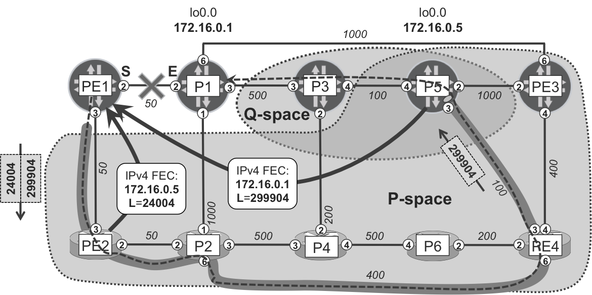
Figure 18-7. Remote LFA P- and Q-spaces for the PE1→P1 link
In the example topology, the PE1→P1 link is not protected with basic LFA. PE2, the only potential backup neighbor of PE1, uses PE1 as the next hop to reach P1, so no loop-free backup next hop is available.
Now, based on RLFA principles, almost all remaining routers (with the exception of the P3 router) belong to P-space. PE1 can reach these routers over the shortest path without crossing the PE1→P1 link. On the other hand, in this particular topology, only P3 and P5 belong to Q-space. Only P3 and P5 can reach P1 over the shortest path without crossing the PE1→P1 link. They will use the P3→P1 link to reach P1.
RLFA functions as follows: PE1 first sends the traffic to some PQ-node (only P5 in the example belongs to both P-space and Q-space). Traffic sent to the PQ-node does not traverse protected links, because this is the definition of P-space. Next, the PQ-node sends the traffic to the destination. Again, based on the definition of Q-space, this traffic does not traverse the protected link.
How does PE1 send packets to destination P1? Simply forwarding packets destined to P1 in the direction of PE2 would cause a loop, because the shortest path from PE2 to P1 is via PE1. Thus, the final destination (P1) of the packet must be invisible to PE2.
To achieve this, PE1 automatically establishes a targeted multihop LDP session to the PQ-node (P5). Over this LDP session, the PQ-Node (P5) sends IPv4 FECs, including the FEC for P1 loopback (172.16.0.1/32). Now, PE1 is able to construct the following label stack for the packets redirected via the PE1→PE2 link toward the PQ-Node.
-
In this example, the outer label is 24004. The backup neighbor (PE2) maps it to P5’s loopback and advertises it to PE1 over the standard LDP session. (In theory, other MPLS transport flavors might be supported, but that’s beyond the scope of this book’s tests.) Thanks to this outer label, which is locally significant to PE2, packets can travel from PE1 to P5.
-
In this example, the inner label is 299904. The PQ-node (P5) maps it to P1’s loopback and advertises it to PE1 over the T-LDP session. Thanks to this inner label, which is locally significant to P5, packets can travel from P5 to P1.
This label stack allows steering the traffic as demonstrated in Figure 18-7, with PHP at PE4 and P3. Because the destination happens to be the E-node (P1), only link protection can be provided; node protection does not even make sense here.
What if the destination is P3’s loopback? In this case, the outer label is the same (24004, to P5 via PE2) and the inner label is the one that the PQ-node (P5) maps to P3 and advertises to PE1 over the T-LDP session. The tunnel is exactly the one depicted in Figure 18-7 (from PE1 to P5), and the dashed-line arrow ends at P3. In this case, traffic from the PQ-node (P5) to the final destination does not traverse the E-node (P1). Said differently, node protection is achieved. This is actually a coincidence. In other topologies, traffic from the PQ-node to the final destination may traverse the E-node.
For example, if the destination is PE3’s loopback and you temporarily increase the metrics of the P5-PE3 and PE3-PE4 links to 8000, the shortest path from PE1 to reach PE3 is PE1→P1→PE3. The shortest path from the PQ-node (P5) to the destination (PE3) is P5→P3→P1→PE3. In case of P1 node failure, there would be traffic loss until the PQ-node is informed about P1’s failure.
In this example, RLFA provides protection for the PE1→P1 link failure. This is a step forward with respect to basic LFA.
RLFA configuration
Now, after discussing the RLFA theory of operation, let’s turn to the configuration for both Junos and IOS XR planes, respectively.
Example 18-25. RLFA configuration (Junos)
1     protocols {
2         isis {
3             backup-spf-options remote-backup-calculation;
4         }
5         ldp {
6             interface lo0.0;
7             auto-targeted-session;
8     }}
Example 18-26. RLFA configuration (IOS XR)
1     group GR-ISIS
2      router isis '.*'
3       interface 'GigabitEthernet.*'
4        address-family ipv4 unicast
5         fast-reroute per-prefix level 2
6         fast-reroute per-prefix remote-lfa tunnel mpls-ldp level 2
7     end-group
8     !
9     router isis core
10     apply-group GR-ISIS
11    !
12    mpls ldp
13     address-family ipv4
14      discovery targeted-hello accept
15    !
In both cases (Junos and IOS XR), you simply enable RLFA functionality with a keyword (Example 18-25, line 3; Example 18-26, line 6). You also need to ensure that local initiation and acceptance of remotely initiated targeted LDP sessions is enabled. Additionally, if filtering of IPv4 FECs is applied to targeted LDP sessions (as briefly discussed in Chapter 2, Chapter 3, and Chapter 4), these filters need to be removed now.
RLFA in action
RFC 7490 doesn’t specify the way to determine the IP address of the remote LFA repair target, referring to it as “out of scope for this document”. This caused some small interoperability problems between Junos and IOS XR. Namely, IOS XR determined the IPv4 address used to establish the targeted LDP (TLDP) session using IS-IS TLV 134 (TE Router ID), and if not available, the highest /32 prefix advertised via TLV 128 or TLV 135 (IP Reachability or Extended IP Reachability). Conversely, Junos determined the IPv4 address from IS-IS TLV 134 exclusively. Although TLV 128/135 is included by default in both Junos and IOS XR implementations, TLV 134 is advertised by default in Junos implementation only. This resulted in Junos routers that were not able to establish TLDP sessions to IOS XR routers. As a workaround, enabling full TE database announcements on IOS XR routers was required (see Chapter 2 and Chapter 13 for the exact TE configuration).
OK, after the configuration is done, take a look at Table 18-5 to check the backup coverage again.
| P1 | P2 | P3 | P4 | P5 | P6 | PE1 | PE2 | PE3 | PE4 |
|---|---|---|---|---|---|---|---|---|---|
| 9 | 9 | 9 | 9 | 9 | 9 | 9 | 3 | 9 | 8 |
| 100% | 100% | 100% | 100% | 100% | 100% | 100% | 33.3% | 100% | 88.9% |
It’s very close to achieving a final design. If you compare Table 18-5 (which shows the current LFA backup coverage) with Table 18-4, you see a considerable increase. This confirms RLFA is useful in increasing backup coverage. However, this also confirms RLFA is still topology dependent because two routers (PE2 and PE4) still do not provide full backup coverage. Later, we’ll cover more advanced techniques to finally achieve full backup coverage. But for now, let’s verify the routing states.
Example 18-27. RIB/LFA entry toward P1 loopback on PE1 (Junos)
juniper@PE1> show isis backup spf results P1 | match <pattern>
  Primary next-hop: ge-2/0/2.0, IPV4, P1, SNPA:  0:50:56:8b:8:f
    Root: P1, Root Metric: 50, Metric: 0, Root Preference: 0x0
      Not eligible, IPV4, Reason: Primary next-hop link fate sharing
    Root: PE2, Root Metric: 50, Metric: 100, Root Preference: 0x0
      Not eligible, IPV4, Reason: Path loops
    Root: P5, Root Metric: 600, Metric: 600, Root Preference: 0x0
      Eligible, Backup next-hop: ge-2/0/3.0, LSP, LDP->P5(172.16.0.5)

juniper@PE1> show isis route 172.16.0.1/32
(...)
Prefix        L Version Metric Interface   NH   Via
172.16.0.1/32 2    1107     50 ge-2/0/2.0  IPV4 P1
                               ge-2/0/3.0  LSP  LDP->P5(172.16.0.5)

juniper@PE1> show route table inet.3 172.16.0.1/32
(...)
172.16.0.1/32 *[LDP/9] 05:17:38, metric 50
          > to 10.0.0.3 via ge-2/0/2.0
            to 10.0.0.1 via ge-2/0/3.0, Push 299904, Push 24004(top)
Perfect! You can see that next-hop type for backup next hop is a LDP-based LSP pointing toward P5. Furthermore, the label stack with two labels is associated with the backup next hop. And the verification of received IPv4 FECs confirms that the top label provides reachability to P5 (PQ-node) through PE2 (direct backup next hop), whereas the bottom label provides reachability to P1 (final destination) from P5 (PQ-node).
Example 18-28. IPv4 FECs received on PE1 (Junos)
juniper@PE1> show ldp database session 172.16.0.22 | match "Inp|24004"
Input label database, 172.16.0.11:0--172.16.0.22:0
  24004      172.16.0.5/32

juniper@PE1> show ldp database session 172.16.0.5 | match "Inp|299904"
Input label database, 172.16.0.11:0--172.16.0.5:0
 299904      172.16.0.1/32
With such a trick, RLFA tunnels the traffic destined for P1 toward P5 through PE2. PE2 looks only at the outer label and politely forwards the traffic to P5. The loop doesn’t occur.
After checking the RLFA operation on a Junos device, let’s verify it on an IOS XR device. As an example let’s have a closer look at the backup for PE2→PE1 link. P-space and Q-space for this case are presented in Figure 18-8.
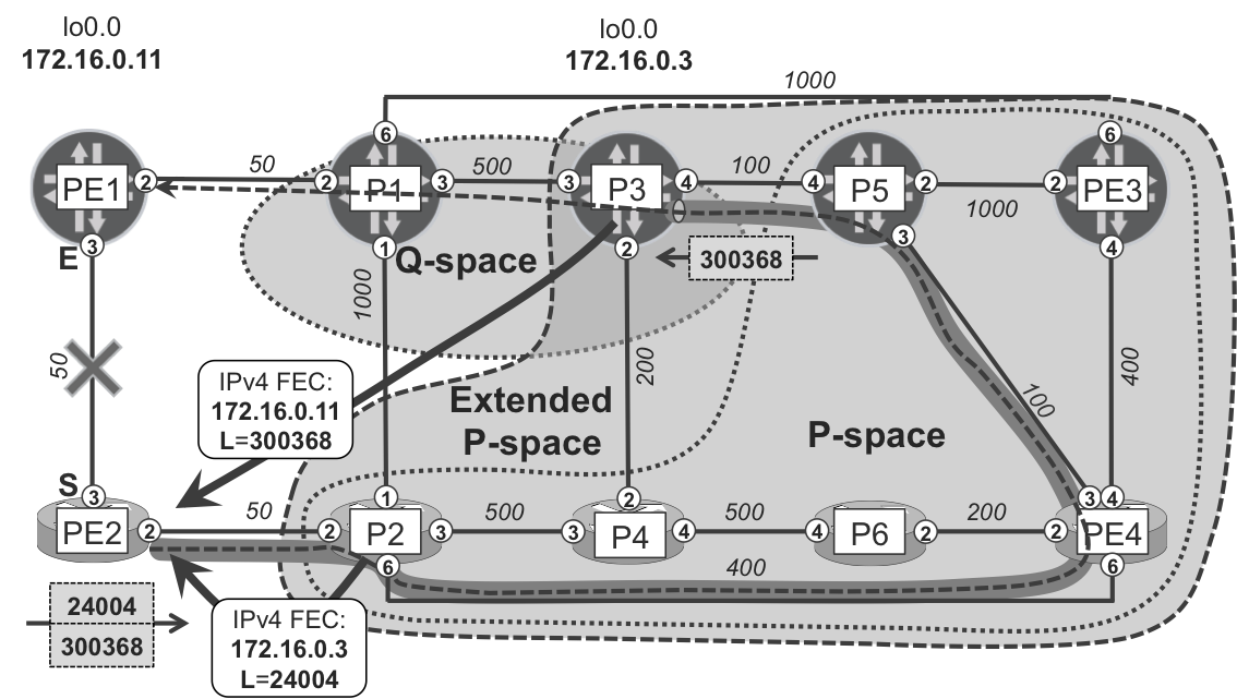
Figure 18-8. Remote LFA P-spaces and Q-space for the PE2→PE1 link
As you can see, there is no overlap between P and Q-space, so no PQ-node. However, even in such situations, there might be cases for which RLFA functionality could still be achieved. When checking protection for the PE2→PE1 link (see the example that follows), you can discover that traffic will be redirected through the LDP tunnel terminated on P3, but going via Gi0/0/0/2 (P2), which is not on the shortest path from PE2 to P3.
Example 18-29. Backup SPF results for PE1 on PE2 (IOS XR)
1     RP/0/0/CPU0:PE2#show isis fast-reroute 172.16.0.11/32 detail
2     L2 172.16.0.11/32 [50/115] medium priority
3        via 10.0.0.0, Gi0/0/0/3, PE1, Weight: 0
4          Remote FRR backup via P3 [172.16.0.3], via 10.0.0.5, Gi0/0/0/2 P2
5          P: No, TM: 650, LC: No, NP: No, D: No, SRLG: Yes
6        src PE1.00-00, 172.16.0.11
How is this possible? Let’s document the trick. PE2 receives IPv4 FECs for P3 loopback (172.16.0.3) from both direct neighbors (PE1 and P2). The shortest path from PE2 to P3 is via PE1 (PE2→PE1→P1→P3, cost 600). So normally, PE2 will send traffic to P3 via PE1, and that is the reason why P3 is not in the P-space. But what about sending the traffic destined to P3 via P2? No loop! The shortest path from P2 to P3 is via P2→P4→P5→P3 (cost 600). Thus, to protect the PE2→PE1 link, PE2 can redirect the traffic via P2, using a standard RLFA label stack (top label: P3; bottom label: PE1). This time, of course, the labels for P3’s and PE1’s loopbacks are allocated by P2 (direct LDP session) and P3 (targeted LDP session), respectively. And here is what actually happens.
Example 18-30. RIB/FIB entry for PE1 loopback on PE2 (IOS XR)
RP/0/0/CPU0:PE2#show route 172.16.0.11/32 | include "from|LFA"
    10.0.0.5, from 172.16.0.11, via Gi0/0/0/2, Backup (remote)
      Remote LFA is 172.16.0.3
    10.0.0.0, from 172.16.0.11, via Gig0/0/0/3, Protected

RP/0/0/CPU0:PE2#show cef 172.16.0.11/32 | include "weight|hop|label"
   via 10.0.0.5, Gi0/0/0/2, 10 dependencies, weight 0, backup
    next hop 10.0.0.5, PQ-node 172.16.0.3
     local label 24001      labels imposed {24004 300368}
   via 10.0.0.0, Gi0/0/0/3, 10 dependencies, weight 0, protected
    next hop 10.0.0.0
     local label 24001      labels imposed {ImplNull}
If you’re reading this correctly, how can PE2 determine which node it should use to redirect the traffic and terminate the RLFA LDP tunnel? Well, here the RLFA RFC introduces the concept of Extended P-space:
- Extended P-space
- The union of P-space computed for PLR router (denoted S) as well as P-spaces computed for each direct neighbor of S, excluding primary next-hop router (denoted E). Calculations based on extended P-space are supported by default in IOS XR and Junos.
Thus, in the example topology, you need to check what P-space is computed from P2’s point of view, as well. P2’s P-space contains all routers with the exception of PE1 and P1. It means P2 can reach all routers (except PE1 and P1) through the shortest path without crossing the PE2→PE1 link. Consequently, P-space is extended with one additional router: P3 (including PE2, the PLR, in the extended P-space does not make sense from the RLFA perspective). P3 belongs to Q-space, fortunately, so it can be used as a PQ-node to terminate the RLFA tunnel.
Note
Going back to Example 18-29, it’s worth mentioning the redefinition of total metric (TM) field. In the case of RLFA, TM means the actual total cost to the PQ-node, not to the destination.
RLFA with RSVP-TE Backup Tunnels
You have seen a lot of configurations already. You have gone through per-link protection, per-prefix protection with various options (node and link protection, link protection, node protection with link protection as fallback), and lastly, remote LFA. All these efforts, although successively increasing LFA backup coverage, did not provide you with the ultimate solution: full backup coverage on all routers. To make things more challenging, you will work on a slightly modified topology now (see Figure 18-9)—without the P2-PE4 direct link—that misses some backup coverage (even with RLFA) for both Junos and IOS XR planes. The following technique takes packets to a Q-node through a non-shortest path, hence extending the effective coverage to 100% (see Table 18-6).

Figure 18-9. LFA topology C—RLFA with RSVP-TE LSP tunnel
| P1 | P2 | P3 | P4 | P5 | P6 | PE1 | PE2 | PE3 | PE4 |
|---|---|---|---|---|---|---|---|---|---|
| 9 | 9 | 9 | 9 | 9 | 9 | 0 | 3 | 9 | 9 |
| 100% | 100% | 100% | 100% | 100% | 100% | 0% | 33.3% | 100% | 100% |
Unfortunately, as you can see in Figure 18-9, the (extended) P-space and Q-space do not share any common node for the PE1→PE2 link. Consequently, standard LDP-based RLFA does not protect the PE1→PE2 link.
What do you do in such a scenario? You could establish an explicitly (not dynamically) routed tunnel to one of the Q nodes (P2 or P4). Because the tunnel is established via the explicit path from source node (PE1) to Q node (e.g., P4), if you configure the path correctly, there is no loop possibility here. The explicit path must be defined to omit the PE1→PE2 link. LDP does not support explicitly routed tunnels, thus your choice is RSVP-TE (or, in theory, SPRING-TE, when available). So, let’s configure it! See Example 18-31.
Example 18-31. RLFA configuration with manual RSVP-TE backup (Junos)
1     protocols {
2         mpls {
3             label-switched-path PE1-->P4-LFA {
4                 backup;
5                 to 172.16.0.4;
6                 ldp-tunneling;
7                 preference 10;
8                 primary PE1-P1-P3-P4;
9             }
10            path PE1-P1-P3-P4 {
11                10.0.0.3 strict;           ## P1
12                10.0.0.9 strict;           ## P3
13                10.0.0.13 strict;          ## P4
14    }}}
Example 18-31 assumes that RLFA is already configured. In addition to enabling TE extensions on the IGP, and RSVP-TE on the interfaces, (which is discussed in Chapter 2), you need to configure an explicitly routed RSVP-TE tunnel to reach the Q-node. Additionally, you must allow the use of this tunnel as a backup tunnel (line 4) in the remote LFA architecture. To prevent the use of this tunnel for normal traffic forwarding, we recommend that you change the route preference to be numerically higher than LDP (line 7) so that the tunnel is less preferred than LDP.
A quick verification, by matching Example 18-32 to Figure 18-9, confirms proper operation. The backup RSVP-TE tunnel is established and LFA uses it as backup next hop toward the loopbacks of three nodes (P2, P4 and PE2). For brevity, the following example shows one destination (P2):
Example 18-32. States for RLFA with manual RSVP-TE backup tunnel (Junos)
juniper@PE1> show mpls lsp ingress detail | match <pattern>
From: 172.16.0.11, State: Up, ActiveRoute: 0, LSPname: PE1-->P4-LFA
ActivePath: PE1-P1-P3-P4 (primary)
LSPtype: Static Configured, Penultimate hop popping
 Computed ERO (S [L] denotes strict [loose] hops): (CSPF metric: 750)
 10.0.0.3 S 10.0.0.9 S 10.0.0.13 S
 Received RRO (ProtectionFlag 1=Available 2=InUse 4=B/W 8=Node
               10=SoftPreempt 20=Node-ID):
          10.0.0.3 10.0.0.9 10.0.0.13

juniper@PE1> show route table inet.3 172.16.0.2/32 detail
[...]*LDP    Preference: 9
             Next hop: 10.0.0.1 via ge-2/0/3.0 weight 0x1, selected
             Label operation: Push 24000
             Next hop: 10.0.0.3 via ge-2/0/2.0 weight 0x100
             Label-switched-path PE1-->P4-LFA
             Label operation: Push 24000, Push 301680(top)
             Age: 6:19:29    Metric: 100

juniper@PE1> show isis backup spf results P2 | except item
(...)
P2.00
  Primary next-hop: ge-2/0/3.0, IPV4, PE2, SNPA:  0:50:56:8b:b3:48
    Root: P4, Root Metric: 600, Metric: 500, Root Preference: 0x0
      Eligible, Backup next-hop: ge-2/0/2.0, LSP, PE1-->P4-LFA
    Root: PE2, Root Metric: 50, Metric: 50, Root Preference: 0x0
      Not eligible, IPV4, Reason: Interface is already covered
    Root: P1, Root Metric: 50, Metric: 150, Root Preference: 0x0
      Not eligible, IPV4, Reason: Interface is already covered
  1 nodes
Similar to the standard LFA case, the backup next hop has a numerically higher weight (this time it is 0x100), and a two-label stack (301680 is the top label to reach the Q-node via the RSVP-TE tunnel, and 24000 is the bottom label to reach the final destination from the Q-node via LDP) is used. Due to PHP, these labels are popped at P3 and P4, respectively.
After investigating the Junos plane, let’s do the same for the IOS XR plane. You can make a detailed analysis again about P- or Q-space for PE2→PE1. But this time let’s simply create backup RSVP-TE tunnels using the PE2→P2→P1→PE1 path to avoid the PE2→PE1 link. Again, in addition to the following configuration, you obviously must enable RSVP-TE itself (not shown for brevity):
Example 18-33. RLFA Configuration with manual RSVP-TE backup tunnel (IOS XR)
group GR-ISIS              ! This group is applied to isis (not shown)
 router isis '.*'
  interface 'GigabitEthernet.*'
   address-family ipv4 unicast
    fast-reroute per-prefix level 2
    fast-reroute per-prefix lfa-candidate interface tunnel-te11 level 2
    fast-reroute per-prefix remote-lfa tunnel mpls-ldp level 2
end-group
!
group GR-LSP-LFA
 interface 'tunnel-te.*'
  ipv4 unnumbered Loopback0
  record-route
end-group
!
explicit-path name PE2-P2-P1-PE1
 index 10 next-address strict ipv4 unicast 10.0.0.5
 index 20 next-address strict ipv4 unicast 10.0.0.6
 index 30 next-address strict ipv4 unicast 10.0.0.2
!
interface tunnel-te11
 apply-group GR-LSP-LFA
 signalled-name PE2-->PE1-LFA
 destination 172.16.0.11
 path-option 1 explicit name PE2-P2-P1-PE1

mpls ldp
 interface tunnel-te11
  address-family ipv4
The following verification confirms that everything works as expected:
Example 18-34. RLFA states with manual RSVP-TE backup tunnel (IOS XR)
RP/0/0/CPU0:PE2#show mpls traffic-eng tunnels | include <pattern>
Name: tunnel-te11  Destination: 172.16.0.11  Ifhandle:0xb80
  Signalled-Name: PE2-->PE1-LFA
    Admin:    up Oper:   up   Path:  valid   Signalling: connected
    path option 1,  type explicit PE2-P2-P1-PE1
                    (Basis for Setup, path weight 1100)

RP/0/0/CPU0:PE2#show route isis | begin /32
i L2 172.16.0.1/32 [115/0] via 172.16.0.11, tunnel-te11 (!)
                   [115/100] via 10.0.0.0, Gi0/0/0/3
i L2 172.16.0.2/32 [115/0] via 10.0.0.0, Gi0/0/0/3 (!)
                   [115/50] via 10.0.0.5, Gi0/0/0/2
i L2 172.16.0.3/32 [115/0] via 172.16.0.11, tunnel-te11 (!)
                   [115/600] via 10.0.0.0, Gi0/0/0/3
i L2 172.16.0.4/32 [115/0] via 10.0.0.0, Gi0/0/0/3 (!)
                   [115/550] via 10.0.0.5, Gi0/0/0/2
i L2 172.16.0.5/32 [115/0] via 172.16.0.11, tunnel-te11 (!)
                   [115/700] via 10.0.0.0, Gi0/0/0/3
i L2 172.16.0.6/32 [115/1000] via 10.0.0.0, Gi0/0/0/3
                   [115/0] via 10.0.0.5, Gi0/0/0/2 (!)
i L2 172.16.0.11/32 [115/0] via 172.16.0.11, tunnel-te11 (!)
                    [115/50] via 10.0.0.0, Gi0/0/0/3
i L2 172.16.0.33/32 [115/0] via 172.16.0.11, tunnel-te11 (!)
                    [115/1100] via 10.0.0.0, Gi0/0/0/3
i L2 172.16.0.44/32 [115/0] via 172.16.0.11, tunnel-te11 (!)
                    [115/800] via 10.0.0.0, Gi0/0/0/3

RP/0/0/CPU0:PE2#show isis fast-reroute 172.16.0.1/32
L2 172.16.0.1/32 [100/115] medium priority
     via 10.0.0.0, Gi0/0/0/3, PE1, Weight: 0
       FRR backup via 172.16.0.11, tunnel-te11, PE1, Weight: 0
     src P1.00-00, 172.16.0.1
It appears, by combining RLFA with the single RSVP-TE tunnel just created, that we’ve increased the backup coverage to 100 percent on PE2! (Refer back to Table 18-6 for the backup coverage without RSVP-TE tunnel.) However, backup forwarding might be suboptimal in some cases. For example, the LFA backup path to reach P1 loopback from PE2 is PE2→P2→P1→PE1→P1. First four hops (up to PE1) uses forwarding via RSVP-TE backup tunnel, and the last hop uses forwarding via plain LDP. P1 is visited twice, which is certainly not optimal.
Before moving on to the next LFA flavor, keep in mind the following characteristics of the “RLFA with RSVP-TE Backup Tunnels” models that we have just discussed:
-
It is an extension of classic RLFA, which only considered LDP backup tunnels, and was originally conceived to provide link protection. In some cases (look back at Figure 18-8), node protection is coincidentally achieved, but that requirement is only considered if
node-link-protectionis configured and draft-ietf-rtgwg-rlfa-node-protection is implemented. -
If protection can be achieved with classic RLFA (without RSVP-TE backup tunnels), then RSVP-TE tunnels, even if configured, are not used.
Neither of these two bullet points hold true in the context of the technology that we’ll look at next.
Topology Independent Fast ReRoute
By introducing additional backup RSVP-TE tunnels (for example, a tunnel originated at PE2 and terminated on P1), you could achieve more optimal forwarding over backup paths. However, in complex network topologies, determining and manually configuring backup RSVP-TE tunnels might be a challenging task. Thus, Junos offers an option for automatic creation of RSVP-TE tunnels used for LFA backups: Topology-Independent Fast ReRoute (TI-FRR), which is based on draft-esale-ldp-node-frr.
Note
As of this writing, IOS XR doesn’t support TI-FRR. However, IOS XR already supports Topology-Independent LFA (TI-LFA), which is based on SPRING tunnels instead of RSVP-TE bypass tunnels. TI-LFA is discussed later in this chapter.
Junos offers two options for automatic bypass RSVP-TE tunnels: tunnels fulfilling link-protection criterion, or tunnels fulfilling node-protection criterion, with fallback to link-protection criterion in case a node-protection tunnel is not possible. Obviously, to provide backup coverage against both node and link failures, we recommend node-link protection bypass RSVP-TE tunnels. So, let’s add node and link-protection tunnels to all the routers in the Junos plane. Following is an example for PE1:
Example 18-35. LFA configuration with dynamic RSVP-TE bypass — PE1 (Junos)
protocols {
    ldp {
        auto-targeted-session;
        interface lo0.0;
        interface ge-2/0/2.0 {
            node-link-protection {         ## or 'link-protection'
                dynamic-rsvp-lsp;
            }
        }
        interface ge-2/0/3.0 {
            node-link-protection {         ## or 'link-protection'
                dynamic-rsvp-lsp;
}}}}
Let’s verify the proper operation. For brevity, the example that follows first shows all of the dynamic LSPs originated at the source node (PE1), but it later focuses on one destination node (P3) only. The protected link is PE1→P1, and the protected next-hop node is P1.
Example 18-36. States for MPLS LFA with dynamic RSVP-TE backup tunnel (Junos)
1     juniper@PE1> show mpls lsp ingress
2     To           From         LSPname
3     172.16.0.1   172.16.0.11  ge-2/0/2.0:BypassLSP->172.16.0.1
4     172.16.0.2   172.16.0.11  Pnode:172.16.0.1:BypassLSP->172.16.0.2
5     172.16.0.2   172.16.0.11  Pnode:172.16.0.22:BypassLSP->172.16.0.2
6     172.16.0.3   172.16.0.11  Pnode:172.16.0.1:BypassLSP->172.16.0.3
7     172.16.0.22  172.16.0.11  ge-2/0/3.0:BypassLSP->172.16.0.22
8     172.16.0.33  172.16.0.11  Pnode:172.16.0.1:BypassLSP->172.16.0.33
9
10    juniper@PE1> show mpls lsp ingress detail | match <pattern>
11    172.16.0.1
12     From: 172.16.0.11, State: Up, ActiveRoute: 0,
13                        LSPname: ge-2/0/2.0:BypassLSP->172.16.0.1
14     ActivePath:  (primary)
15     LSPtype: Dynamic Configured, Penultimate hop popping
16      Computed ERO (S [L] denotes strict [loose]): (CSPF metric: 1100)
17    10.0.0.1 S 10.0.0.5 S 10.0.0.6 S
18       Received RRO:
19              10.0.0.1 10.0.0.5 10.0.0.6
20    (...)
21    172.16.0.3
22     From: 172.16.0.11, State: Up, ActiveRoute: 0,
23                        LSPname: Pnode:172.16.0.1:BypassLSP->172.16.0.3
24     ActivePath:  (primary)
25     LSPtype: Dynamic Configured, Penultimate hop popping
26      Computed ERO (S [L] denotes strict [loose] hops): (CSPF metric: 100)
27     10.0.0.1 S 10.0.0.5 10.0.0.11 10.0.0.12 S
28        Received RRO:
29              10.0.0.1 10.0.0.5 10.0.0.11 10.0.0.12
30    (...)
31
32    juniper@PE1> show isis backup spf results P3 | except item
33    (...)
34    P3.00
35      Primary next-hop: ge-2/0/2.0, IPV4, P1, SNPA:  0:50:56:8b:8:76
36        Root: P3, Root Metric: 550, Metric: 0, Root Preference: 0x0
37          Eligible, Backup next-hop: ge-2/0/3.0, LSP,
38                    Pnode:172.16.0.1:BypassLSP->172.16.0.3, Prefixes: 3
39    (...)
40
41    juniper@PE1> show route table inet.3 172.16.0.3/32 detail | match ...
42        *LDP    Preference: 9
43                Next hop: 10.0.0.3 via ge-2/0/2.0 weight 0x1, selected
44                Label operation: Push 299776
45                Next hop: 10.0.0.1 via ge-2/0/3.0 weight 0x100
46                Label-switched-path Pnode:172.16.0.1:BypassLSP->172.16.0.3
47                Label operation: Push 24031
48                Age: 9  Metric: 550
The bypass RSVP-TE tunnels are dynamically established, and LFA can use these tunnels as backup next hops for all prefixes that still don’t have a backup next hop. You can see the following protection tunnels:
-
Two link-protection tunnels (lines 3 and 7), whose name encodes the protected interface name as well as the router ID of the next-hop node, where the LSP is terminated.
-
Four node-protection tunnels (lines 4 through 6 and line 8), whose name encodes the next-hop node being protected, and the next-next-hop node, where the LSP is terminated.
Two link-protection tunnels are pretty obvious: PE1 has only two links. But, why do you see four node-protection tunnels for two neighbor nodes? Well, there are four possible ways to reach a next-next-hop:
-
PE1→P1→P2 (protected via Pnode:172.16.0.1:BypassLSP->172.16.0.2)
-
PE1→PE2→P2 (protected via Pnode:172.16.0.22:BypassLSP->172.16.0.2)
-
PE1→P1→P3 (protected via Pnode:172.16.0.1:BypassLSP->172.16.0.3)
-
PE1→P1→PE3 (protected via Pnode:172.16.0.1:BypassLSP->172.16.0.33)
To put it simply, PE1 can send traffic to one of the following next hops: P1 or PE2. Then, P1 has three possible next hops (excluding the undesirable option of returning the traffic to PE1): P2, P3, and PE3. In turn, PE2 has one single possible next hop: P2.
In the absence of failures, PE1 sends packets destined to P3 via the PE1→P1 link. PE1 can choose between a link-protection bypass (lines 3, and 11 through 19) and a node-protection bypass (lines 6, and 21 through 29). According to the configuration, PE1 prefers the node-protection bypass (lines 38 and 46).
When TI-FRR is enabled, backup LFA or RLFA next hops are no longer used. All backup next hops point to bypass RSVP-TE tunnels. This time the backup next hop has a weight of 0x100 (line 45). As you explore different local-repair techniques used in Junos platforms, you’ll see that each of them uses a different weight for backup next hops, therefore it is easy to determine the relative priority of the different next hops.
Let’s verify the overall coverage provided by TI-FRR.
Example 18-37. States for TI-FRR (Junos)
juniper@PE1> show isis backup coverage
Backup Coverage:
Topology        Level   Node    IPv4    IPv6    CLNS
IPV4 Unicast        2 100.00% 100.00%   0.00%   0.00%
Now you have finally achieved 100 percent backup coverage! And, it is completely topology independent. Whatever the topology the backup coverage is always 100 percent.
Modifying the default LFA selection algorithm
In many cases, multiple feasible (loop-free) backup next hops might be available. These backup next hops could be direct (for plain per-prefix LFA) or point to a remote PQ-node (when using Remote LFA). A legitimate question would be then: How do you select the best backup next hop among those that are possible? And immediately a second question arises: How do you actually define best? Best for one network operator might not be the best for another. Typically, a default algorithm selects the best backup next hop. Just for reference, default tie-breakers in the LFA backup next-hop selection process, for both Junos and IOS XR, are as follows:
- Junos
-
-
Prefer direct (another primary) ECMP next hop.
-
For multihomed prefixes, if PLR is the penultimate router, prefer direct backup next hop to another (non-best) originator if
per-prefix-calculationis configured. -
Prefer backup next hop (direct or PQ-node), which provides node protection if
node-link-protectionconfigured. -
Prefer backup next hop (direct or PQ-node), which provides link protection, if
link-protectionornode-link-degradationconfigured. -
Prefer backup next hop (direct or PQ-node) over a link with LDP synchronization enabled and LDP
in-syncstate. -
Prefer backup next hop (direct or PQ-node) closest to the destination.
-
Prefer backup next hop (direct or PQ-node) closest to PLR.
-
Prefer backup next hop (direct or PQ-node) with lowest System ID.
-
- IOS XR
-
-
Prefer direct (another primary) ECMP next-hop.
-
Prefer backup next hop with the lowest-total-metric (actually, lowest
TM) backup path. -
Prefer backup next hop reachable using different line card than the primary next hop.
-
Prefer backup next hop, which provides node protection.
-
Note
Keep rule 1 in mind. If a backup next hop is not installed, the reason might simply be that another primary next hop (ECMP) is already providing the desired protection.
Even at first sight, the default LFA backup next hop selection process is different. And, of course, it might not suit every operator’s needs. Therefore, it should be possible to influence the default LFA backup next-hop selection process. The requirements for this are provided in draft-ietf-rtgwg-lfa-manageability: Operational management of Loop Free Alternates.
Both IOS XR and Junos offer a wide range of selection criteria, and provide ways to specify the order in which these criteria should be evaluated:
- Junos
- Backup path administrative constraints:
-
-
Based on administrative groups (affinity bits)
-
Based on Shared Risk Link Group (SRLG)
-
- Bandwidth: For example, the bandwidth over the backup path should be greater or equal to the bandwidth available over primary path.
- Protection type:
-
-
Link protection
-
Node and link protection
-
Node protection with fallback to link protection if node protection not available
-
- Downstream paths only.
- Backup neighbors preference:
-
-
Preference list based on IP addresses
-
Preference list based on ISIS tags
-
- Metrics:
-
-
Metric from PLR to backup neighbor: highest of lowest
-
Metric from backup neighbor to destination: highest or lowest
-
- IOS XR
- Backup path administrative constraints:
-
-
Based on SRLG
-
- Protection type:
-
-
Node protection with fallback to link protection if node protection not available
-
- Downstream paths preferred.
- Metrics:
-
-
Backup path with lowest total metric (actually, lowest
TM) preferred
-
- Line card disjoint backup path preferred
- ECMP:
-
-
ECMP path preferred
-
Non-ECMP path preferred
-
Due to the great variety of possible options, this book selects a few in order to introduce policy-based LFA backup next-hop selection. You are encouraged to test the others.
Modifying the default LFA selection algorithm in Junos
In the topology illustrated in Figure 18-10, let’s assume that RLFA (without RSVP-TE backup tunnels, and with node-link-protection) is configured on PE3. Figure 18-10 illustrates three paths from the source node (PE3) to the destination node (P2):
-
The (shortest-path) primary path, which is PE3→P1→PE1→PE2→P2.
-
The backup path that PE3 calculates according to the default backup next-hop selection algorithm, which chooses P4 as PQ-node. PE3 pushes a bottom (TLDP) label to go from P4 to P2, and a top (LDP) label for the tunnel PE3→P5→P3→P4. This LDP tunnel does not follow the shortest path from PE3 to P4. The reason will be explained later in this section.
-
The backup path that PE3 calculates according to a modified backup next-hop selection algorithm. This modification consists of reversing Step 6 (prefer backup next hop closest to the destination) with Step 7 (prefer backup next hop closest to PLR). PE3 pushes a bottom (TLDP) label to go from P4 to P2, and a top (LDP) label for the tunnel PE3→PE4→P6→P4.
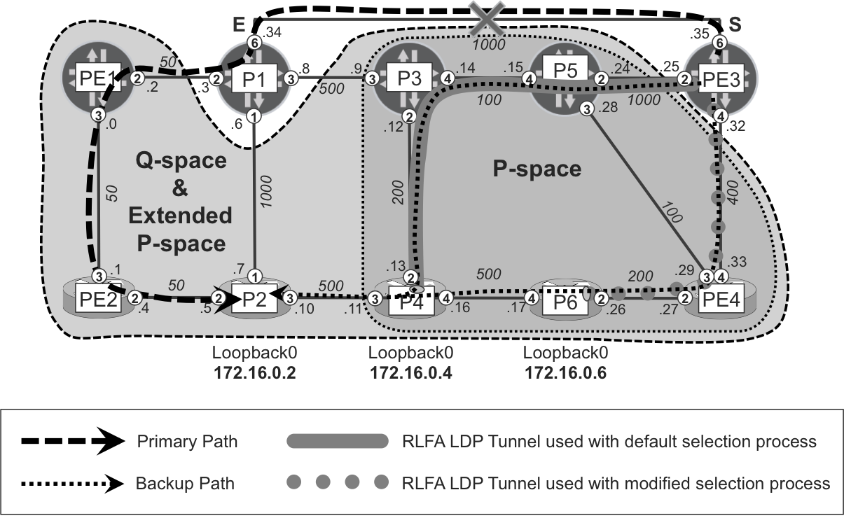
Figure 18-10. Modified LFA next-hop selection process (Junos)
First, let’s check at PE3 the backup next hop selected by the default LFA selection process implemented in Junos.
Example 18-38. States toward P2 with default LFA selection process—PE3 (Junos)
1     juniper@PE3> show isis backup spf results P2 | except item
2     (...)
3     P2.00
4      Primary next-hop: ge-2/0/6.0, IPV4, P1, SNPA:  0:50:56:8b:16:af
5        Root: P2, Root Metric: 1150, Metric: 0, Root Preference: 0x0
6          Not eligible, LSP, Reason: Primary next-hop node fate sharing
7        Root: PE2, Root Metric: 1100, Metric: 50, Root Preference: 0x0
8          Not eligible, LSP, Reason: Primary next-hop node fate sharing
9        Root: PE1, Root Metric: 1050, Metric: 100, Root Preference: 0x0
10         Not eligible, LSP, Reason: Primary next-hop node fate sharing
11       Root: P1, Root Metric: 1000, Metric: 150, Root Preference: 0x0
12         Not eligible, IPV4, Reason: Primary next-hop link fate sharing
13       Root: P4, Root Metric: 800, Metric: 500, Root Preference: 0x0
14         Eligible, Backup next-hop: ge-2/0/2.0, LSP, LDP->P4(172.16.0.4)
15                                    Prefixes: 1
16       Root: P3, Root Metric: 600, Metric: 650, Root Preference: 0x0
17         Not eligible, IPV4, Reason: Primary next-hop node fate sharing
18         Not eligible, LSP, Reason: Interface is already covered
19       Root: P5, Root Metric: 500, Metric: 750, Root Preference: 0x0
20         Not eligible, IPV4, Reason: Primary next-hop node fate sharing
21       Root: PE4, Root Metric: 400, Metric: 850, Root Preference: 0x0
22         Not eligible, IPV4, Reason: Primary next-hop node fate sharing
23       Root: P6, Root Metric: 600, Metric: 1000, Root Preference: 0x0
24         Not eligible, IPV4, Reason: Missing primary next-hop
25         Not eligible, LSP, Reason: Interface is already covered
26
27    juniper@PE3> show route table inet.3 172.16.0.2/32 detail | match ...
28    172.16.0.2/32 (1 entry, 1 announced)
29             Next hop: 10.0.0.34 via ge-2/0/6.0 weight 0x1, selected
30             Label operation: Push 301168
31             Next hop: 10.0.0.24 via ge-2/0/2.0 weight 0xf100
32             Label operation: Push 24003, Push 300800(top)
Example 18-38 illustrates that the shortest path from PE3 to P2 is via P1 (lines 4 and 29). Currently the (remote) backup next hop, selected using the default LFA backup next hop selection process, is P4 (line 14). In most of the other evaluated backup next hops, their reason for noneligibility is Primary next-hop node fate sharing. That basically means that the end-to-end backup path through these next hops crosses P1, which is the primary node. Because node-link-protection is used in this example, these backup paths do not provide the required node diversity.
The only exception is P6. It says Missing primary next-hop (line 24) for IPv4, which means that P6 cannot be used as a direct backup next hop, because it is not directly connected to PE3. It also says Interface is already covered (line 25) for LSP, which means that P6 is not used as remote (PQ-node) backup next-hop, because a better backup next hop has been already selected.
But why exactly has P4 been selected as the best LFA backup next hop? Why not P6? Let’s try to evaluate the default LFA backup next-hop selection criteria specified earlier.
-
Prefer direct (another primary) ECMP next hop.
P2 is reachable via single (no ECMP) primary next-hop, so this verification criterion is invalid for all feasible next hops.
-
For multihomed prefixes, if PLR is the penultimate router, prefer direct backup next hop to another (non-best) originator.
Loopback of P2 is single-homed, so this verification criterion is invalid for all feasible next hops.
-
Prefer backup next hop (direct or PQ-node), which provides node protection if
node-link-protectionis configured.In this example,
node-link-protectionhas been configured. It means that at this step only backup next hops that offer node protection are selected. Let’s evaluate all feasible next hops:P1 P1 is the primary next hop, so it cannot be used as backup next hop
P2 The shortest path to reach P2 from PE3 is via PE3→P1→PE1→PE2→P2. So, P2 does not belong to PE3 P-space, because the path crosses a primary link (PE3→P1). On the other hand, P2 belongs to extended P-space, because the shortest path from PE3’s neighbors (P5→P3→P1→PE1→PE2→P2 and PE4→P5→P3→P1→PE1→PE2→P2) does not use the PE3→P1 link. However, in both cases the path traverses a primary next hop (P1), thus P2 as a backup next hop does not provide node protection, just link protection, and is therefore disqualified as potential backup next hop.
PE1, PE2 The situation is similar to P2. PE1 or PE2 do not belong to P-space; rather, they belong to extended P-space. And again, the path from PE3’s neighbors to PE1 or PE2 traverses P1, so they provide only link protection, but not node protection; therefore they are disqualified as potential backup next hops.
P4 The shortest path to reach P4 from PE3 is via PE3→PE4→P5→P3→P4. And further, the shortest path from P4 to P2 is via direct link. Thus, you can conclude that P4 belongs to P-space, and neither path from PE3 to P4, nor from P4 to P2, crosses P1. As a result, P4 provides both node and link protection.
P6 The shortest path to reach P6 from PE3 is via PE3→PE4→P6. And further, the shortest path from P6 to P2 is via P6→P4→P2. Thus, P6 provides both node and link protection.
P3 The shortest path to reach P3 from PE3 is via PE3→PE4→P5→P3, so it does not cross P1. However, the shortest path from P3 to P2 is P3→P1→PE1→PE2→P2. Thus, P3 provides only link protection and therefore is not used as potential backup next-hop.
P5, PE4 Both nodes are direct neighbors of PE3 and feasible backup next hops. The shortest path ([PE4→]P5→P3→P1→PE1→PE2→P2) from either node to P2 crosses P1. Thus, these next hops provide only link protection, so again they are disqualified.
Consequently, you can conclude that the only possible backup next hops in this step of the selection process are P4 and P6.
-
Prefer backup next hop (direct or PQ-node), which provides link protection if
link-protectionornode-link-degradationis configured.Both previously selected backup next-hops (P4 and P6) provide link protection (in addition to node protection) so this criterion is equal for all selected backup next-hops.
-
Prefer backup next hop (direct or PQ-node) over a link with LDP synchronization enabled and LDP
in-syncstate.Network is stable, thus all LDP adjacencies are in
in-syncstate. -
Prefer backup next hop (direct or PQ-node) closest to the destination.
The path cost from P4 to P2 is 500 (P4→P2), whereas the path cost from P6 to P2 is 1000 (P6→P4→P2). Therefore, in this step, P4 is selected as preferred next hop.
-
Prefer backup next hop (direct or PQ-node) closest to PLR
Single-backup next hop is already selected.
-
Prefer backup next hop (direct or PQ-node) with lowest System ID
Single backup next hop is already selected.
So, after a detailed analysis of the default LFA backup next hop selection process, you can conclude that the backup path is PE3→P5→P3→P4→P2. Why is PE4 skipped? PE3 is clever enough to realize that the shortest path from PE3 to P4 goes via P5, which is a directly connected neighbor. RLFA makes this exception to the “LDP follows the IGP” rule.
Now, let’s make the appropriate configuration changes to influence the selection process.
Example 18-39. Policy LFA (tie-breakers) configuration on PE3 (Junos)
1     routing-options {
2         backup-selection {
3             destination 172.16.0.2/32 {
4                 interface all {
5                     root-metric lowest;
6                     dest-metric lowest;
7                     metric-order [ root dest ];
8                     evaluation-order metric;
9     }}}}
In this configuration example, the LFA backup path selection process is changed only for a single prefix (172.16.0.2/32) regardless of what the primary interface for the prefix is (lines 3 and 4). Furthermore, lower metrics are preferred from the PLR to the backup next hop (line 5) and from the backup next hop to the destination (line 6). Next, you specify the order in which the metrics should be evaluated (line 7).
Your choice is to first evaluate the metric from PLR to the backup next hop, and only after that, evaluate the metric from the backup next hop to the destination. If you recall the Junos default LFA selection process, this is just the opposite. And, finally (in line 8), the only specified criterion in the overall LFA backup next-hop selection process is the metric. In this particular case, you don’t specify other selection criteria, so the evaluation order consists of a single item. If you specified additional criteria, such as bandwidth requirements, you could indicate if the bandwidth or the metric should be evaluated first in the LFA backup next-hop selection process.
Okay, let’s check to see if the selection has changed.
Example 18-40. States toward P2 with modified LFA selection process—PE3 (Junos)
1     juniper@PE3> show isis backup spf results P2 | except item
2     (...)
3     P2.00
4      Primary next-hop: ge-2/0/6.0, IPV4, P1, SNPA:  0:50:56:8b:16:af
5     (...)
6        Root: P4, Root Metric: 800, Metric: 500, Root Preference: 0x0
7          Eligible, Backup next-hop: ge-2/0/2.0, LSP, LDP->P4(172.16.0.4)
8                                     Prefixes: 0
9     (...)
10       Root: P6, Root Metric: 600, Metric: 1000, Root Preference: 0x0
11          Eligible, Backup next-hop: ge-2/0/4.0, LSP, LDP->P6(172.16.0.6)
12                                     Prefixes: 1
13
14    juniper@PE3> show route table inet.3 172.16.0.2/32 detail | match ...
15    172.16.0.2/32 (1 entry, 1 announced)
16                 Next hop: 10.0.0.34 via ge-2/0/6.0 weight 0x1, selected
17                 Label operation: Push 301168
18                 Next hop: 10.0.0.33 via ge-2/0/4.0 weight 0x101
19                 Label operation: Push 24006, Push 24003(top)
Let’s compare this output to that of Example 18-38. First, backup SPF results now include all possible backup next hops in the Eligible state. So, the RLFA tunnel to P6 (line 10) is now explicitly mentioned. Second, the remote (PQ-node) backup next hop has changed to P6 as indicated by the nonzero number of protected prefixes (line 12). Why did the backup next hop change? Based on the configuration changes in Example 18-39, the path cost from PLR to backup next hop (step 7 in the original selection process) is now evaluated before the path cost from the backup next hop to destination (Step 6 in original selection process). The path cost from PE3 to P6 is 600, whereas the path cost from PE3 to P4 is 800. Thus, P6 is selected as the backup next hop.
Because P6 is reachable via PE4, the direct backup next hop changed from P5 to PE4 (line 18). If you compare the outputs carefully, you will also realize that the weight of the backup next hop changed (from 0xf100 to 0x101). In Junos, every type of backup next hop uses a different weight, and now the backup next hop is delivered by the nondefault LFA selection algorithm. Basically, the backup path changed from PE3→P5→P3→P4→P2 to PE3→PE4→P6→P4→P2, successfully modifying the LFA selection!
Let’s explore other verification commands related to policy-based LFA.
Example 18-41. Modified LFA selection process verification—PE3 (Junos)
juniper@PE3> show backup-selection
Prefix: 172.16.0.2/32
 Interface: all
  Protection Type: Link, Downstream Paths Only: Disabled, SRLG: Loose
  B/w >= Primary: Disabled, Root-metric: lowest, Dest-metric: lowest
  Metric Evaluation Order: Root-metric, Dest-metric
  Policy Evaluation Order: Metric

juniper@PE3> show isis route 172.16.0.2/32
(...)
Prefix         Interface  NH   Via                    Backup Score
172.16.0.2/32  ge-2/0/6.0 IPV4 P1
               ge-2/0/4.0 LSP  LDP->P6(172.16.0.6) 0000000000000010
The show backup-selection command displays the information about nondefault LFA backup selection elements and reflects the configuration specified in Example 18-39. The show isis route command now displays a Backup Score value. While evaluating the LFA selection policy, each backup path is assigned a backup score, which is a composite, 64-bit entity containing 8 blocks of 8 bits. Each of the evaluation criteria contributes to an 8-bit block in the backup score. The evaluation-order (see Example 18-39, line 8) determines the offset of the block. The criterion at the beginning of the evaluation-order list is assigned the biggest offset, such that its block becomes most significant. Because a single evaluation criterion is listed in the example, the offset for that criterion is null, so it occupies the rightmost block. Finally, the result with the biggest score wins.
Modifying the default LFA selection algorithm in IOS XR
After checking the modified LFA selection process in Junos devices, let’s verify the feature in the IOS XR plane. The topology depicted in Figure 18-11 shows three different paths from the source node (PE4) to the destination node (P2). You can modify the selection process by introducing SRLG verification, which by default, is not evaluated in the standard LFA selection process. First, let’s examine the results of the default selection process.
Example 18-42. States toward P2 with default LFA selection process—PE4 (IOS XR)
1     RP/0/0/CPU0:PE4#show isis fast-reroute 172.16.0.2/32 detail
2     L2 172.16.0.2/32 [850/115] medium priority
3       via 10.0.0.28, Gi0/0/0/3, P5, SRGB Base: 0, Weight: 0
4         FRR backup via 10.0.0.26, Gi0/0/0/2, P6, SRGB Base: 0, Weight: 0
5         P: No, TM: 1200, LC: No, NP:Yes, D: No, SRLG: No
6       src P2.00-00, 172.16.0.2
7
8     RP/0/0/CPU0:PE4#show cef 172.16.0.2/32 | include "via|label"
9        via 10.0.0.26, Gi0/0/0/2, 7 dependencies, weight 0, backup
10         local label 24007      labels imposed {24006}
11       via 10.0.0.28, Gi0/0/0/3, 7 dependencies, weight 0, protected
12         local label 24007      labels imposed {300864}
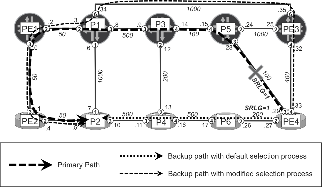
Figure 18-11. Modified LFA next-hop selection process—IOS XR
Note
As you can see in Example 18-42, there is no label stacking. Conversely, if PE4 ran Junos, there would be label stacking by default, because PE4 would select the backup neighbor closest to the destination. In this case, it is PQ-node P4 (instead of the direct neighbor P6) reachable via an LDP tunnel..
Example 18-42 shows that the shortest path from PE4 to P2 is via P5 (lines 3 and 11). Currently the backup next hop (selected using the default LFA backup next hop selection process) is P6 (lines 4 and 9). The end-to-end backup path is PE4→P6→P4→P2 with a cost of 1200 (TM: 1200 statement in line 5). Additionally, the current backup path not only provides link protection, but also node protection (see NP: Yes in line 5), which means the backup path does not cross P5.
Furthermore, for this example, the same SRLG value is assigned to PE4-P5 and PE4-P6 links, by using the configuration discussed in Chapter 13. Therefore, the current backup path via P6 shares the same SRLG value with the primary path via P5. In other words, the primary and backup paths are not SRLG disjoint. This is emphasized via the SRLG: No statement (line 5), which is expected, because the default LFA backup next-hop selection algorithm does not take SRLG into consideration.
Let’s change this. Obviously, as was discussed in Chapter 13, SRLG is used on purpose—to signify that links with the same SRLG value share the risk. During network failure (for example, a cut fiber) they might fail at the same time. Therefore, there is no point in placing primary and backup paths over links that use the same SRLG value. Let’s reflect that into the configuration.
Example 18-43. LFA tie-breakers configuration on PE4 (IOS XR)
router isis core
 address-family ipv4 unicast
  fast-reroute per-prefix tiebreaker srlg-disjoint index 1
Let’s verify and see if any of the changes can be observed.
Example 18-44. States for P2 with modified LFA selection process—PE4 (IOS XR)
1     RP/0/0/CPU0:PE4#show isis fast-reroute 172.16.0.2/32 detail
2     L2 172.16.0.2/32 [850/115] medium priority
3       via 10.0.0.28, Gi0/0/0/3, P5, SRGB Base: 0, Weight: 0
4         FRR backup via 10.0.0.32, Gi0/0/0/4, PE3, SRGB Base: 0, Weight: 0
5         P: No, TM: 1550, LC: No, NP: Yes, D: No, SRLG: Yes
6       src P2.00-00, 172.16.0.2
7
8     RP/0/0/CPU0:PE4#show cef 172.16.0.2/32 | include "via|label"
9        via 10.0.0.28, Gi0/0/0/3, 7 dependencies, weight 0, protected
10         local label 24007      labels imposed {300864}
11       via 10.0.0.32, Gi0/0/0/4, 7 dependencies, weight 0, backup
12         local label 24007      labels imposed {300352}
Perfect! The backup next hop changed to PE3 (lines 4 and 11). The total cost of the backup path certainly increased (TM: 1550 in line 5), and now the backup path is completely different (PE4→PE3→P1→PE1→PE2→P2). Node protection is still achieved (P5 is not used by the backup path), and, remarkably, the new backup path is SRLG disjoint with the primary path (SRLG: Yes in line 5).
There are many possible ways to influence the default LFA backup next-hop selection process. Some examples were provided in this section for you to understand the concepts. Again, you should explore more possibilities on your own; the limited space of this book does not allow us to have all the fun we want, so we’ve only explored the topic in scant detail.
Topology-Independent LFA
Topology-Independent LFA (TI-LFA), as the name suggests, is another approach to provide backup coverage independent of the network topology. TI-LFA, as opposed to TI-FRR (which uses RSVP-TE bypass tunnels), is based on the SPRING technology discussed in Chapter 2, and it is defined in draft-francois-rtgwg-segment-routing-ti-lfa: Topology Independent Fast Reroute using Segment Routing.
There are two main characteristics of TI-LFA:
- When calculating the backup path, TI-LFA temporarily removes the protected resource (link or node) from the topology database, and runs standard SPF. Therefore, the backup path calculated by TI-LFA has, among all the paths that skip the protected resource, the lowest total metric to the final destination. This is called the shortest post-convergence path.
- TI-LFA constructs traffic engineered repair tunnel to follow this backup path using SPRING machinery. It uses the repair label list, which is a combination of Node and Adjacency Segment IDs, as already discussed in Chapter 2 (see for example Figure 2-9). Depending on the backup path calculation results, one of the following options are possible:
- Option 1: The repair node is a direct neighbor
- When the repair node (backup next hop) is a direct neighbor, the outgoing interface is set to that neighbor and the repair label list is empty (there is no repair label).
- This is comparable to the plain per-prefix LFA local repair discussed earlier.
- Option 2: The repair node is a PQ-node
- When the repair node (remote backup next hop) is a PQ-node, the repair label list comprises a single Node Segment ID to the repair node (PQ-node).
- This is comparable to the RLFA architecture discussed previously. Of course, now the backup tunnel to PQ-node is established via SPRING model, rather than LDP.
- Option 3: The repair is a Q-node, direct neighbor of the P-node
- When the repair node (a Q-node, used as remote backup next hop) is directly connected to the P-node, the repair label list comprises two segments: a Node Segment ID to the P-node, and an Adjacency Segment ID from that P-node to the repair node (Q-node).
- This protection method is called Direct LFA (DLFA) and it requires the advertisement of a label (Adjacency Segment ID) for each IGP adjacency, which is the default in both Junos and IOS XR.
- Option 4: Connecting distant (nondirectly connected) P-nodes and Q-nodes
- In some cases, there might not be any adjacent P-nodes and Q-nodes. However, the PLR can perform additional computations to compute a list of segments (combination of Node and Adjacency Segment IDs) that represent a loop-free path from P to Q. The actual computation algorithm is not specified in the TI-LFA draft; it is left to the actual implementation. Furthermore, the computation in this option is CPU intensive.
For link protection, TI-LFA with Options 1 through 3 provides full coverage in any arbitrary redundant network topology with symmetrical link metrics. TI-LFA Option 4 – computationally the most expensive – might be required for link protection only in topologies with asymmetric link metrics. On the other hand, for node or SRLG protection, in order to provide 100% coverage, option 4 might be required even in topologies with symmetrical link metrics. Option 4 was not tested by the authors.
Note
The standard label, based on Node-SID associated with the final destination, is added below the repair label list when sending traffic via the backup next hop (unless the repair label list already takes the packet to the destination node).
As of this writing, TI-LFA was still in early standardization state, therefore the implementation status for both vendors was different, as shown next. IOS XR implemented TI-LFA for link protection only (no node protection) using a backup path computation algorithm that calculated the optimized (lowest total cost) post-convergence path (as specified in TI-LFA draft). After calculating this path, it encoded the repair tunnel via SPRING repair label list according to the options listed previously. Therefore, IOS XR’s TI-LFA provided full link-protection coverage in any arbitrary topology with symmetrical IGP metrics, but did not provide node-protection coverage. Junos, on the other hand, didn’t use the backup path computation method specified in TI-LFA draft. Instead, Junos used the standard LFA or RLFA backup next-hop selection procedure discussed in the “Modifying the default LFA selection algorithm” section. The resulting repair path uses a SPRING repair list from either Option 1 (direct backup neighbor, no label) or Option 2 (PQ-node as remote backup neighbor, node-SID label), but no Option 3 yet. Therefore, the backup tunnel was not necessarily on the shortest post-convergence path to the destination. In conclusion, Junos SPRING implementation provided protection for both link and node failures, but not for arbitrary topologies. Therefore, to avoid any misunderstanding, we will refer in this book to Junos implementation as simply SPRING-(R)LFA.
Note
Junos actually implements the shortest post-convergence path logic for a different flavor of local protection. Check the “RSVP-TE one-to-one protection” section in Chapter 19 for more details.
So, let’s configure SPRING-(R)LFA/TI-LFA on both Junos and IOS XR planes, exploiting the LFA topology C we already used in the previous section (see Figure 18-9). Both planes are configured for pure SPRING operation (LDP-related configuration parts are removed) with the addition of (TI)-LFA specific configuration. For reference, these configurations are presented in the following two examples.
Example 18-45. TI-LFA configuration on PE4 (IOS XR)
group GR-ISIS
 router isis '.*'
  interface 'GigabitEthernet.*'
   address-family ipv4 unicast
    fast-reroute per-prefix level 2
    fast-reroute per-prefix ti-lfa level 2
end-group
!
router isis core
 apply-group GR-ISIS
 address-family ipv4 unicast
  segment-routing mpls
 !
 interface Loopback0
  address-family ipv4 unicast
   prefix-sid index 44
Example 18-46. SPRING-(R)LFA configuration on PE3 (Junos)
groups {
    GR-ISIS {
        protocols {
            isis {
                interface "<*[es]*>" {
                    node-link-protection;
}}}}}
protocols {
    isis {
        apply-groups GR-ISIS
        backup-spf-options {
            remote-backup-calculation;
            node-link-degradation;
        }
        source-packet-routing {
            use-mpls-forwarding;
            node-segment {
                ipv4-index 33;
                index-range 256;
}}}}
And again, you first check the LFA backup coverage. As Table 18-7 confirms, full backup coverage is achieved on (almost) all routers, so it is truly topology independent. On PE1 (Junos, no support for Option 3 or Option 4), you can extend backup coverage by using the backup RSVP-TE tunnel method, also discussed earlier, in this case for primary tunnels based on SPRING instead of LDP.
| P1 | P2 | P3 | P4 | P5 | P6 | PE1 | PE2 | PE3 | PE4 |
|---|---|---|---|---|---|---|---|---|---|
| 9 | 9 | 9 | 9 | 9 | 9 | 0 | 9 | 9 | 9 |
| 100% | 100% | 100% | 100% | 100% | 100% | 0% | 100% | 100% | 100% |
Note
As of this writing, SPRING-(R)LFA on Junos platforms was not truly topology independent, due to missing Option 3 and Option 4 in the Junos implementation. On the other hand, TI-FRR provided topology-independent backup coverage on Junos.
TI-LFA with direct repair node
Our first scenario for the repair tunnel is the situation in which the repair node (backup next hop) is a direct neighbor of PLR, as demonstrated next for IOS XR. In the following example, PE2 is the source node, P6 is the destination node, and P2 is the repair node:
Example 18-47. TI-LFA with direct repair node (IOS XR)
1     RP/0/0/CPU0:PE2# show isis fast-reroute 172.16.0.6/32 detail
2     L2 172.16.0.6/32 [1000/115] medium priority
3      via 10.0.0.0, Gi0/0/0/3, PE1, SRGB Base: 800000, Weight: 0
4       FRR backup via 10.0.0.5, Gi0/0/0/2, P2, SRGB Base: 16000, Weight: 0
5       P: No, TM: 1050, LC: No, NP: Yes, D: No, SRLG: Yes
6      src P6.00-00, 172.16.0.6, prefix-SID index 6, R:0 N:1 P:0 E:0 V:0 L:0
7
8     RP/0/0/CPU0:PE2#show cef 172.16.0.6/32 | include "via|label"
9        via 10.0.0.5, Gi0/0/0/2, 20 dependencies, weight 0, backup
10         local label 24007      labels imposed {16006}
11       via 10.0.0.0, Gi0/0/0/3, 20 dependencies, weight 0, protected
12         local label 24007      labels imposed {800006}
Example 18-47 is not illustrated, but it is based on LFA Topology C (see Figure 18-9 or Figure 18-12). On PE2, P6 loopback is reachable via PE1 (lines 3 and 11) as the primary next hop (via PE2→PE1→P1→P3→P5→PE4→P6, with path cost 1000), and a standard LFA selects P2 (lines 4 and 9) as the backup next hop (via PE2→P2→P4→P6, with path cost 1050). Because the standard LFA is able to find a backup next-hop, no repair label list is used. Simply put, for the primary next hop (PE1), PE2 combines P6’s Node-SID index 6 (line 6) with PE1’s node SRGB 800000 (line 3) to calculate label 800006 (line 12). If the PE2→PE1 link (or the PE1 node) fails, PE2 redirects traffic destined for P6 over the backup next hop (P2), by combining P6’s Node-SID index 6 (line 6) with P2’s SRGB 16000 (line 4) to calculate label 16006 (line 10).
Now, let’s see the feature in Junos. In the following example, PE3 is the source node, P3 is the destination node, and P5 is the repair node:
Example 18-48. SPRING-(R)LFA with direct repair node (Junos)
juniper@PE3> show isis backup spf results P3
(...)
P3.00
  Primary next-hop: ge-2/0/4.0, IPV4, PE4, SNPA:  0:50:56:8b:0:43
    Root: P5, Root Metric: 500, Metric: 100, Root Preference: 0x0
      Eligible, Backup next-hop: ge-2/0/2.0, IPV4, P5
(...)
juniper@PE3> show route table inet.3 172.16.0.3/32 detail |
             match "entry|via|oper"
172.16.0.3/32 (1 entry, 1 announced)
            Next hop: 10.0.0.33 via ge-2/0/4.0 weight 0x1, selected
            Label operation: Push 16003
            Next hop: 10.0.0.24 via ge-2/0/2.0 weight 0xf000
            Label operation: Push 800003
Similarly, in the Junos plane, the Node-SID index of final destination (P3), coupled with the SRGB of the primary next-hop (PE4: 16000), or the backup next-hop (P5: 800000), is used to determine the outgoing label.
TI-LFA with PQ repair node
The second scenario mentioned in the TI-LFA draft deals with the PQ-node and is similar to the RLFA case discussed previously. This scenario is illustrated in Figure 18-12.
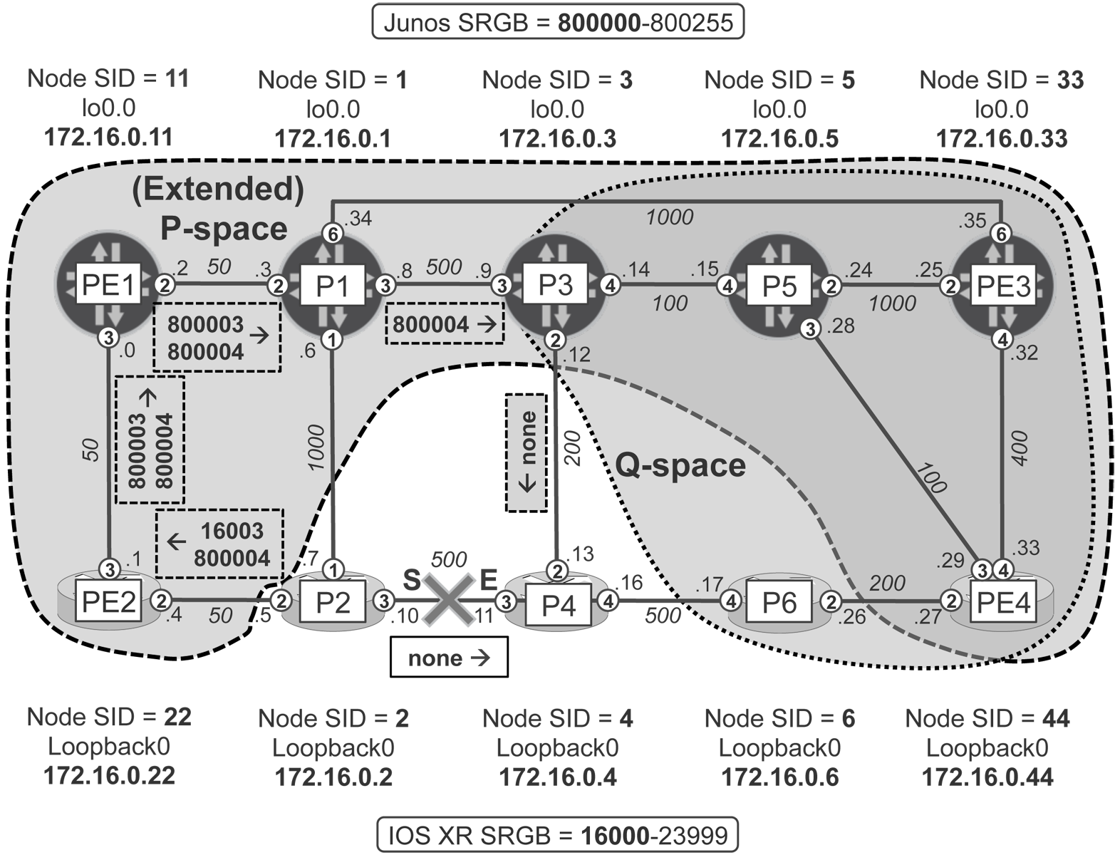
Figure 18-12. TI-LFA with RLFA (PQ-node) Style Repair
Let’s see this TI-LFA flavor in IOS XR. In the following example (illustrated in Figure 18-12), P2 is the source node, P4 is the destination node, and P3 is the repair node:
Example 18-49. TI-LFA with PQ-node (IOS XR)
1     RP/0/0/CPU0:P2#show isis fast-reroute 172.16.0.4/32 detail
2     L2 172.16.0.4/32 [500/115] medium priority
3       via 10.0.0.11, Gi0/0/0/3, P4, SRGB Base: 16000, Weight: 0
4         TI-LFA backup via P3 (PQ) [172.16.0.3]
5         via 10.0.0.4, Gi0/0/0/2 PE2, SRGB Base: 16000
6         Label stack [16003, 800004]
7         P: No, TM: 850, LC: No, NP: No, D: No, SRLG: Yes
8       src P4.00-00, 172.16.0.4, prefix-SID index 4, R:0 N:1 P:0 E:0 V:0 L:0
9
10    RP/0/0/CPU0:P2#show cef 172.16.0.4/32 | include "via|label"
11       via 10.0.0.4, Gi0/0/0/2, 10 dependencies, weight 0, backup
12         local label 24006      labels imposed {16003 800004}
13       via 10.0.0.11, Gi0/0/0/3, 10 dependencies, weight 0, protected
14         local label 24006      labels imposed {ImplNull}
As with the RLFA case, the label stack associated with the backup next hop ensures delivery to the PQ-node first, and then delivery from the PQ-node to the final destination. The PQ-node is P3 (line 4); thus, the top label is derived from P3’s Node-SID: P3’s Node-SID index 3 + PE2’s (backup next hop) SRGB 16000 (line 5) = 16003 (lines 6 and 12). The second label is derived from P4’s (final destination) Node-SID index 4 (line 8) + P3’s (PQ-Node) SRGB (800000) = 800004 (lines 6 and 12). When the packet is forwarded on the backup path (P2→PE2→PE1→P1→P3→P4) the first label is swapped to the label derived from P3’s Node-SID. The penultimate hop for P3 (P1) removes the first label; consequently, the packet arrives at P3 with a single label only (based on P4’s Node-SID). And again, the penultimate hop for P4 (P3) removes that single label, so the packet arrives to P4 without any label.
For the primary next hop, there are no labels (line 14) due to Penultimate Hop Popping (PHP). P4 is directly connected to P2; thus, P2 is the penultimate hop for P4.
In the Junos plane the situation is similar. Let’s verify it. In the following example, P5 is the source node, P4 is the destination node, and P2 is the repair node:
Example 18-50. SPRING-(R)LFA with PQ-node (Junos)
1     juniper@P5> show isis backup spf results P4
2     (...)
3     P4.00
4      Primary next-hop: ge-2/0/4.0, IPV4, P3, SNPA:  0:50:56:8b:e6:da
5       Root: P2, Root Metric: 750, Metric: 500, Root Preference: 0x0
6        Eligible, Backup next-hop: ge-2/0/2.0, LSP, SPRING->P2(172.16.0.2)
7     (...)
8     juniper@P5> show route table inet.3 172.16.0.4/32 detail | match ...
9     172.16.0.4/32 (1 entry, 1 announced)
10              Next hop: 10.0.0.14 via ge-2/0/4.0 weight 0x1, selected
11              Label operation: Push 800004
12              Next hop: 10.0.0.25 via ge-2/0/2.0 weight 0xf000
13              Label operation: Push 16004, Push 800002(top)
For example, to reach P4 from P5, the PQ-node is P2 (line 6). Thus, the top label is derived from P2’s Node-SID: P2’s Node-SID index 2 + PE3’s (backup next hop) SRGB 800000 = 800002 (line 13). The second label is derived from P4’s (final destination) Node-SID index 4 + P2’s (PQ-Node) SRGB (16000) = 16004 (line 13). For the primary next hop, there is a single label derived from P4’s Node-SID coupled with P3’s SRGB: 4 + 800000 = 800004 (line 11).
TI-LFA with direct LFA (DLFA) repair
The third scenario describes the situation in which P-node and Q-node are disjointed but directly connected. In this situation, using the Direct LFA model, traffic can be forced to flow from the P-node toward the Q-node, despite the fact the IGP shortest path from P-node to Q-node does not necessarily go over the direct link. Let’s investigate PE2→PE1 traffic, as illustrated in Figure 18-13.
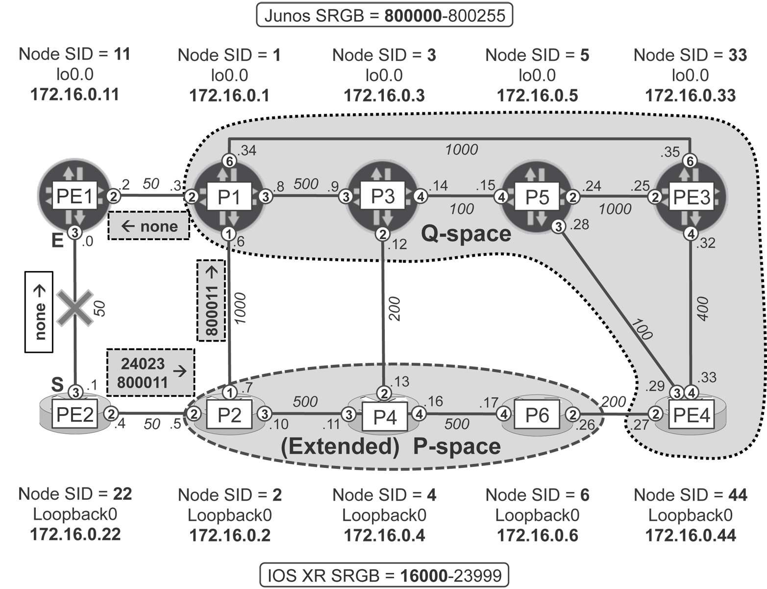
Figure 18-13. TI-LFA with DLFA (adjacent P- and Q-node)–style repair
For the PE2→PE1 link, the P-space (nodes that PE2 can reach over shortest path without going via the PE2→PE1 link) and the Q-space (nodes that can reach PE1 over shortest path without going via the PE2→PE1 link) do not overlap, and therefore there is no PQ-node. RLFA-style protection is consequently not possible.
The good news is that by using Adj-SID, you can force the traffic to go from the P-node via a direct link to the Q-node. And fortunately, there are a couple of adjacent P- and Q-nodes, for example, P1 and P2.
So, let’s see how it looks in the network.
Example 18-51. TI-LFA with disjoint but adjacent P-node and Q-node (IOS XR)
1     RP/0/0/CPU0:PE2#show isis fast-reroute 172.16.0.11/32 detail
2     L2 172.16.0.11/32 [50/115] medium priority
3          via 10.0.0.0, Gi0/0/0/3, PE1, SRGB Base: 800000, Weight: 0
4            TI-LFA backup via P2 (P) [172.16.0.2], P1 (Q) [172.16.0.1]
5            via 10.0.0.5, GigabitEthernet0/0/0/2 P2, SRGB Base: 16000
6            Label stack [ImpNull, 24023, 800011]
7            P: No, TM: 1100, LC: No, NP: No, D: No, SRLG: Yes
8          src PE1.00-00, 172.16.0.11, prefix-SID index 11, R:0 N:1 ...
9
10    RP/0/0/CPU0:PE2#show cef 172.16.0.11/32 | include "via|label"
11       via 10.0.0.5, Gi0/0/0/2, 18 dependencies, weight 0, backup
12         local label 24003    labels imposed {ImplNull 24023 800011}
13       via 10.0.0.0, Gi0/0/0/3, 18 dependencies, weight 0, protected
14         local label 24003    labels imposed {ImplNull}
15
16    RP/0/0/CPU0:PE2#show isis database P2 verbose | include "IS|SRGB|SID"
17    IS-IS core (Level-2) Link State Database
18        Segment Routing: I:1 V:0, SRGB Base: 16000 Range: 8000
19      Metric: 50         IS-Extended PE2.00
20        ADJ-SID: F:0 B:0 V:1 L:1 S:0 weight:0 Adjacency-sid:24025
21      Metric: 500        IS-Extended P4.00
22        ADJ-SID: F:0 B:0 V:1 L:1 S:0 weight:0 Adjacency-sid:24024
23      Metric: 1000       IS-Extended P1.00
24        ADJ-SID: F:0 B:0 V:1 L:1 S:0 weight:0 Adjacency-sid:24023
25        Prefix-SID Index: 2, R:0 N:1 P:0 E:0 V:0 L:0
The primary next hop for PE2→PE1 traffic is PE1 itself, with no label (PHP) associated (line 14). The label stack associated with the backup next hop must ensure three actions:
-
PE2 must send the traffic to P-node (P2).
This is similar to reaching the PQ-node discussed in the previous case. The label is derived from the Node-SID of the P-node. In the particular case of Figure 18-13, however, the P-node (P2) is directly connected to PE2, thus there is no label associated with this step due to penultimate hop popping (see
ImpNullin lines 6 and 12). -
P-node (P2) must send the traffic to Q-node (P1) over direct link.
This is a new action, not discussed previously. If the label derived from P1 Node-SID was used for this purpose, traffic would be forwarded from P2 to P1 over the shortest path: P2→PE2→PE1→P1, which isn’t good, because the backup path must avoid the PE2→PE1 link. Therefore, instead of Node-SID used in all previous cases, Adj-SID is used. P2 advertises Adj-SID labels for each IGP adjacency: PE2, P1, or P4. The label associated with neighbor P1 is 24023 (line 24). Any packet arriving to P2 with this label will be sent to P1 not using the shortest path, but over a direct link. This is good for the TI-LFA scenario because it allows forcing the traffic to the directly-connected Q-node. Therefore, this label is used as a second label in the label stack (lines 6 and 12). This behavior is called Direct LFA.
-
Q-node (P1) must send the traffic to the final destination (PE1).
There’s nothing new here compared to the previous case. PE1’s Node-SID index 11 (line 8) is used in combination with SRGB of the Q-node to reach PE1 through the Q-node (P1). P1’s SRGB (800000) is used, therefore the resulting label is 800011 (line 6 and line 12).
Note
In LDP-based RLFA, the TM field in show isis fast-reroute output encodes the path cost to the PQ-node (Example 18-29, line 5). In TI-LFA, however, the TM field retains its original meaning: total cost of the backup path (Example 18-49, line 7; Example 18-51, line 7).
Another example of TI-LFA protection with disjoint but adjacent P-nodes and Q-nodes, is the protection for PE2→PE4 traffic, which uses PE2→PE1→P1→P3→P5→PE4 as a primary path. P4 is P-node and P3 the Q-node, as is shown in the following capture:
Example 18-52. TI-LFA with disjoint but adjacent P-node and Q-node (IOS XR)
RP/0/0/CPU0:PE2#show isis fast-reroute 172.16.0.44/32
L2 172.16.0.44/32 [800/115]
     via 10.0.0.0, Gi0/0/0/3, PE1, SRGB Base: 800000, Weight: 0
       TI-LFA backup via P4 (P) [172.16.0.4], P3 (Q) [172.16.0.3]
       via 10.0.0.5, Gi0/0/0/2 P2, SRGB Base: 16000
       Label stack [16004, 24011, 800044]
In this example, the following labels are used:
-
16004: Node-SID to reach P4 (P-node) from PE2 via P2
-
24001: Adj-SID to reach P3 (Q-node) via direct link from P4 (P-node)
-
800044: Node-SID to reach PE4 from P3
Theoretically P3 Node-SID could be used to forward traffic between P4 (P-node) and P3 (Q-node), because the shortest path between P4 and P3 is via a direct link. Moreover, the label stack with two labels only—skipping Adj-SID between P4 and P3—would be enough, too, because the shortest path from P4 (P-node) to PE4 (final destination) does not cross the PE2→PE1 link. However, such additional verification of the shortest path between the P-node and the Q-node or final destination node requires additional SPF calculation, where the P-node is placed as the SPF root. In large networks (hundreds of nodes with potentially hundreds or thousands of P-nodes), that would eventually mean the PLR needs to perform hundreds (if not thousands) of SPF calculations on each IGP topology change. This is very challenging from a performance perspective, and as a result, such additional optimization is typically not implemented in the TI-LFA process.
The last case mentioned in the TI-LFA draft differs from previous cases in that the P-node and the Q-node are not directly connected. Thus, simple Adj-SID to force the traffic from the P-node to the Q-node cannot be used. However, the PLR can perform additional computations to compute a list of segments (combination of Node and Adjacency Segment IDs) from these particular P-nodes. Depending on the network size and the topology, this computation might cause performance challenges.
The resulting list of segments is explicitly path-encoded in the label stack to forward traffic from the P-node to the nonadjacent Q-node. Again, depending on the network topology the list of segments (and corresponding label stack size) might be long. This puts additional requirements on routers to support larger label stacks, which might not be available on all router hardware platforms.
Maximally Redundant Trees
Maximally Redundant Trees (MRT) is another approach that provides local-repair-based protection capabilities in LDP-signaled networks. All previously discussed techniques were based on SPF calculations (performed from the perspective of the node in question as well as the node’s neighbors, and eventually the node’s neighbors’ neighbors) to find a loop-free backup next hop. Then, various techniques were discussed to patch the network with some backup tunnels (LDP, RSVP-TE, or SPRING–based) to eventually extend backup coverage.
As of this writing, MRT was still in draft state and defined in several drafts.
MRT provides answers to all of the issues learned during our LFA deployments:
-
It provides protection in any arbitrary topology. In other words, MRT is topology independent.
-
It provides protection for both unicast and multicast traffic flows from day one (LFA focuses primarily on unicast traffic).
-
MRT computation efforts are low (comparable to three SPF computations) in any arbitrary topology (RLFA computation efforts depend on the number of neighbors and neighbors’ neighbors).
So, what is MRT? In MRT, three forwarding paths (essentially next hops) are always computed to reach the final destination. One forwarding path (next hop) is computed by using an ordinary SPF algorithm. The other two forwarding paths (next hops) are computed using a newly defined (draft-ietf-rtgwg-mrt-frr-algorithm) computation algorithm. This, rather complex to understand, algorithm does not try to optimize the forwarding paths based on metrics, distance, or hop count. Such optimization is the responsibility of standard SPF algorithm. On the other hand, MRT ensures that both MRT forwarding paths (called MRT-red and MRT-blue) are disjointed (do not share common links or nodes) to the maximum possible degree; hence, the name: Maximally Redundant Trees. As a result of such computation, during protection events (lasting few 100 ms up to few seconds) MRT might redirect the traffic over a suboptimal path.
Note
The details of MRT (or ordinary SPF) computation algorithm are not covered in this book. You are encouraged to study the appropriate drafts for further information on the MRT computation algorithm itself.
Different MPLS labels distinguish all three forwarding paths. Therefore, MRT extensions to the LDP protocol allow allocation of three labels for each IPv4 prefix advertised by LDP.
Note
As of this writing, MRT was not supported in production routing software, but you can try it in Junosphere. Unlike xLFA solution, MRT is a global solution requiring other IGP nodes to contribute to the protection. Hence it requires global deployment in the IGP, or at least in the context of routing islands.
Now, after this very short overview and introduction, let’s verify MRT operation in practice. In addition to standard (node-link protection) LFA (not shown for brevity) you need to enable MRT operation.
Example 18-53. MRT backup configuration (Junos)
routing-options mrt;
After enabling MRT on all routers in the topology, let’s check different LDP traceroutes to the same destination using standard SPF, as well as MRT-red and MRT-blue forwarding paths.
Example 18-54. LDP traceroute to PE1 using SPF, MRT-red, and MRT-blue forwarding—P3 (Junos)
juniper@P3> show route table inet.3 172.16.0.11/32 detail | match ...
*LDP  Preference: 9
      Next hop: 10.0.0.8 via ge-0/0/3.0 weight 0x1        ## Primary
      Next hop: 10.0.0.13 via ge-0/0/2.0 weight 0xf000    ## Backup

juniper@P3> traceroute mpls ldp 172.16.0.11/32
  ttl    Label  Protocol    Address     Previous Hop     Probe Status
    1   300608  LDP         10.0.0.8    (null)           Success
    2        3  LDP         10.0.0.2    10.0.0.8         Egress
(...)
juniper@P3> traceroute mpls ldp 172.16.0.11/32 mrt-red
  ttl    Label  Protocol    Address     Previous Hop     Probe Status
    1   300576  LDP         10.0.0.13   (null)           Success
    2   300144  LDP         10.0.0.10   10.0.0.13        Success
    3   300704  LDP         10.0.0.4    10.0.0.10        Success
    4        3  LDP         10.0.0.0    10.0.0.4         Egress
juniper@P3> traceroute mpls ldp 172.16.0.11/32 mrt-blue
  ttl    Label  Protocol    Address     Previous Hop     Probe Status
    1   300368  LDP         10.0.0.15   (null)           Success
    2   300400  LDP         10.0.0.29   10.0.0.15        Success
    3   300528  LDP         10.0.0.32   10.0.0.29        Success
    4   300688  LDP         10.0.0.34   10.0.0.32        Success
    5        3  LDP         10.0.0.2    10.0.0.34        Egress
(...)
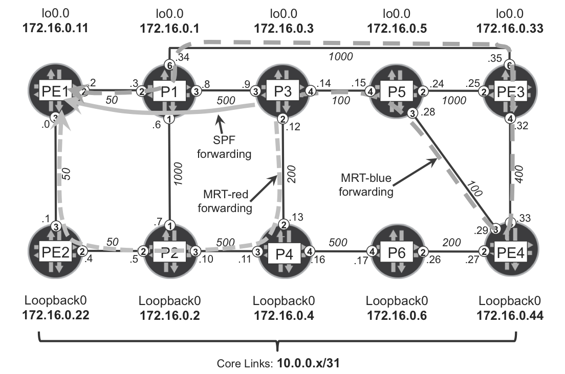
Figure 18-14. Forwarding paths from P3 to PE1 Using SPF, MRT-red, and MRT-blue forwarding topologies
As you can see, MPLS-red and MPLS-blue use disjointed paths to reach PE1 from P3. In this particular case, neither MRT-red nor MRT-blue uses the same path as the SPF path. Depending on the actual topology, though, it may happen that one of the MRT paths equals the SPF path.
But why does forwarding over (nonshortest) MRT paths not cause loops? For example, the shortest paths from P5 to PE1 is via P3; thus, theoretically, the packet destined to PE1 arriving from P3 at P5 should be sent back to P3 causing a loop. The trick that MRT uses, as we’ve briefly mentioned, is the allocation of three MPLS labels for each loopback. And, of course, implementation of appropriate extensions to LDP to ensure that the three labels for each prefix can be advertised.
Example 18-55. LDP SPF and MRT FECs on P3 (Junos)
juniper@P3> show ldp database | match "Input|Output|172.16.0.11/32"
Input label database, 172.16.0.3:0--172.16.0.1:0
 300608      172.16.0.11/32
 300752      172.16.0.11/32, MRT Red
 300688      172.16.0.11/32, MRT Blue
Output label database, 172.16.0.3:0--172.16.0.1:0
 299872      172.16.0.11/32
 300064      172.16.0.11/32, MRT Red
 299968      172.16.0.11/32, MRT Blue
Input label database, 172.16.0.3:0--172.16.0.4:0
 300336      172.16.0.11/32
 300576      172.16.0.11/32, MRT Red
 300848      172.16.0.11/32, MRT Blue
Output label database, 172.16.0.3:0--172.16.0.4:0
 299872      172.16.0.11/32
 300064      172.16.0.11/32, MRT Red
 299968      172.16.0.11/32, MRT Blue
Input label database, 172.16.0.3:0--172.16.0.5:0
 300320      172.16.0.11/32
 300512      172.16.0.11/32, MRT Red
 300368      172.16.0.11/32, MRT Blue
Output label database, 172.16.0.3:0--172.16.0.5:0
 299872      172.16.0.11/32
 300064      172.16.0.11/32, MRT Red
 299968      172.16.0.11/32, MRT Blue
The computation algorithms to calculate SPF, MRT-red, and MRT-blue forwarding trees are consistent on all routers. It means that each forwarding topology (SPF, MRT-red, and MRT-blue) is loop-free. Based on the forwarding topology calculation, appropriate forwarding states are configured in the forwarding plane. The forwarding states for SPF topology uses SPF labels, whereas the forwarding states for the MRT-red or MRT-blue topologies use labels allocated for MRT-red or MRT-blue, respectively. As soon as the packet is sent with, for example, an MRT-blue label, it is switched (loop-free) through the network using MRT-blue labels only.
Now, when the standard LFA backup next hop cannot be found, the MRT next hop (either from MRT-red or MRT-blue—whichever is different from SPF next hop) will be used as the backup LFA next hop. Let’s have a look for example at PE3.
Example 18-56. MRT—LDP routes on PE3 (Junos)
juniper@PE3> show ldp route | find 172.16.0.1/32
 172.16.0.1/32  ge-0/0/6.0                  10.0.0.34 IP
                ge-0/0/2.0                  10.0.0.24 IP
                ge-0/0/4.0                  10.0.0.33 MRT Red
                ge-0/0/6.0                  10.0.0.34 MRT Blue
 172.16.0.2/32  ge-0/0/6.0                  10.0.0.34 IP
                MRT Backup->10.0.0.33(no LDP tunneling)MRT Backup LSP
                ge-0/0/4.0                  10.0.0.33 MRT Red
                ge-0/0/6.0                  10.0.0.34 MRT Blue
 172.16.0.3/32  ge-0/0/4.0                  10.0.0.33 IP
                ge-0/0/2.0                  10.0.0.24 IP
                ge-0/0/4.0                  10.0.0.33 MRT Red
                ge-0/0/6.0                  10.0.0.34 MRT Blue
 172.16.0.4/32  ge-0/0/4.0                  10.0.0.33 IP
                ge-0/0/2.0                  10.0.0.24 IP
                ge-0/0/4.0                  10.0.0.33 MRT Red
                ge-0/0/6.0                  10.0.0.34 MRT Blue
 172.16.0.5/32  ge-0/0/4.0                  10.0.0.33 IP
                ge-0/0/2.0                  10.0.0.24 IP
                ge-0/0/4.0                  10.0.0.33 MRT Red
                ge-0/0/6.0                  10.0.0.34 MRT Blue
 172.16.0.6/32  ge-0/0/4.0                  10.0.0.33 IP
                MRT Backup->10.0.0.34(no LDP tunneling)MRT Backup LSP
                ge-0/0/4.0                  10.0.0.33 MRT Red
                ge-0/0/6.0                  10.0.0.34 MRT Blue
 172.16.0.11/32 ge-0/0/6.0                  10.0.0.34 IP
                MRT Backup->10.0.0.33(no LDP tunneling)MRT Backup LSP
                ge-0/0/4.0                  10.0.0.33 MRT Red
                ge-0/0/6.0                  10.0.0.34 MRT Blue
 172.16.0.22/32 ge-0/0/6.0                  10.0.0.34 IP
                MRT Backup->10.0.0.33(no LDP tunneling)MRT Backup LSP
                ge-0/0/4.0                  10.0.0.33 MRT Red
                ge-0/0/6.0                  10.0.0.34 MRT Blue
 172.16.0.33/32 lo0.0                       IP
 172.16.0.44/32 ge-0/0/4.0                  10.0.0.33 IP
                ge-0/0/2.0                  10.0.0.24 IP
                ge-0/0/4.0                  10.0.0.33 MRT Red
                ge-0/0/6.0                  10.0.0.34 MRT Blue
As you can see, for the five loopbacks (P1, P3, P4, P5, and PE4) the basic LFA provides backup next hops (you see two IP next hops for each of these loopbacks). For the other four loopbacks (P2, P6, PE1, and PE2), the backup next hop is provided by MRT. The backup next hop for P2, PE1, and PE2 is inherited from MRT-red. MRT-blue cannot be used as a backup next hop, because the MRT-blue next-hop matches the SPF next hop for these loopbacks in this particular topology. For the P6 loopback, it is just the opposite. The SPF next hop matches the MRT-red next hop; thus, the MRT-blue is used as the backup next hop. This is confirmed with the following detailed backup SPF output:
Example 18-57. LFA states for P6 loopback on PE3 (Junos)
juniper@PE3> show ospf backup spf 172.16.0.6
(...)
172.16.0.6
  Self to Destination Metric: 600
  Parent Node: 172.16.0.44
  Primary next-hop: ge-0/0/4.0 via 10.0.0.33
  Backup next-hop: Push 300336
  Backup Neighbor: 172.16.0.1
  Alternate Source: MRT Blue
   Neighbor to Destination Metric: 0, Neighbor to Self Metric: 1000
   Self to Neighbor Metric: 1000, Backup preference: 0x0
   Eligible, Reason: Contributes backup next-hop
  Backup Neighbor: 172.16.0.44
  Alternate Source: LFA
   Neighbor to Destination Metric: 200, Neighbor to Self Metric: 400
   Self to Neighbor Metric: 400, Backup preference: 0x0
   Not eligible, Reason: Primary next-hop node fate sharing
  Backup Neighbor: 172.16.0.5
  Alternate Source: LFA
   Neighbor to Destination Metric: 300, Neighbor to Self Metric: 500
   Self to Neighbor Metric: 500, Backup preference: 0x0
   Not eligible, Reason: Primary next-hop node fate sharing
  Backup Neighbor: 172.16.0.1
  Alternate Source: LFA
   Neighbor to Destination Metric: 900, Neighbor to Self Metric: 1000
   Self to Neighbor Metric: 1000, Backup preference: 0x0
   Not eligible, Reason: Primary next-hop node fate sharing

juniper@PE3> show ldp database session 172.16.0.1 | match ...
Input label database, 172.16.0.33:0--172.16.0.1:0
 300384      172.16.0.6/32, MRT Red
 300336      172.16.0.6/32, MRT Blue
Output label database, 172.16.0.33:0--172.16.0.1:0
 300960      172.16.0.6/32, MRT Red
 300752      172.16.0.6/32, MRT Blue
In case of the primary link or primary node (PE4) failure, traffic destined for P6 will be switched to the MRT-blue forwarding topology and forwarded with the MRT-blue label over interfaces towards P1. P1, again using the MRT-blue forwarding topology, not SPF forwarding topology, forwards the traffic further over the appropriate interface.
And, what is a very important aspect of MRT, Table 18-8 shows that full backup coverage is always achieved, regardless of the network topology.
Example 18-58. LFA backup coverage with MRT extensions on PE3 (Junos)
juniper@PE3> show ospf backup coverage
(...)
Area             Covered  Total  Percent
                   Nodes  Nodes  Covered
0.0.0.0                9      9  100.00%

Route Coverage:

Path Type  Covered   Total  Percent
            Routes  Routes  Covered
Intra           20      24   83.33%
Inter            0       0  100.00%
Ext1             0       0  100.00%
Ext2             0       0  100.00%
All             20      24   83.33%
Note
The coverage output for routes does not reach 100 percent, because local prefixes (in the case of the three PE3 link prefixes and one loopback prefix) are always counted as noncovered.
| P1 | P2 | P3 | P4 | P5 | P6 | PE1 | PE2 | PE3 | PE4 |
|---|---|---|---|---|---|---|---|---|---|
| 9 | 9 | 9 | 9 | 9 | 9 | 9 | 9 | 9 | 9 |
| 100% | 100% | 100% | 100% | 100% | 100% | 100% | 100% | 100% | 100% |