
Chapter 2. The Four MPLS Builders
Depending on the function of a Multiprotocol Label Switching (MPLS) label, it can receive many names: transport label, service label, VPN label, entropy label, and so on. This chapter focuses on the original and primary function of MPLS labels: the transport of data packets through a labeled tunnel.
Chapter 1 describes how MPLS tunnels are provisioned by using a static label-mapping technique. However, this approach is limited in terms of scalability, operability, failure detection, and redundancy. There is fortunately a classic solution at hand: signaling the tunnels with protocols that create MPLS paths in a dynamic manner. What protocols? There are actually a few of them, each with their pros and cons.
This chapter covers the following alternatives:
-
Two pure MPLS signaling protocols: Label Distribution Protocol (LDP) and Resource Reservation Protocol with Traffic Engineering (RSVP-TE)
-
The modern MPLS extensions of classic IP routing protocols: Border Gateway Protocol (BGP), Intermediate System–to–Intermediate System (IS-IS), and Open Shortest-Path First (OSPF)
BGP has had MPLS extensions since the early times, and they keep evolving. As for IS-IS and OSPF, their MPLS extensions have come more recently with a technology called SPRING or Segment Routing. SPRING, which was still in IETF draft state at the time of the publication of this book, also has extensions for BGP.
The four MPLS Builders are therefore: LDP, RSVP-TE, BGP, and the Interior Gateway Protocol (IGP). LDP was already proposed in the 1990s, so why are there so many other MPLS signaling protocols? First, LDP did not cover the Traffic Engineering use case, so RSVP-TE was soon proposed for that purpose. And because neither LDP nor RSVP-TE nicely solved the interdomain use case, new BGP extensions were defined to achieve it. Some scenarios are a good fit for LDP, or for RSVP-TE, or for BGP, or for a combination of them. As for SPRING, most of its use cases can be covered by a combination of other protocols (LDP, RSVP-TE, and BGP), but it is a recent technology whose applications are diversifying, it brings deterministic labels to the table, and it is very interesting to see how you can use the IGP to build MPLS LSPs.
Let’s begin with LDP, probably the most classic and widespread of them all. The baseline topology is borrowed from Chapter 1. For convenience, it is also displayed here in Figure 2-1.
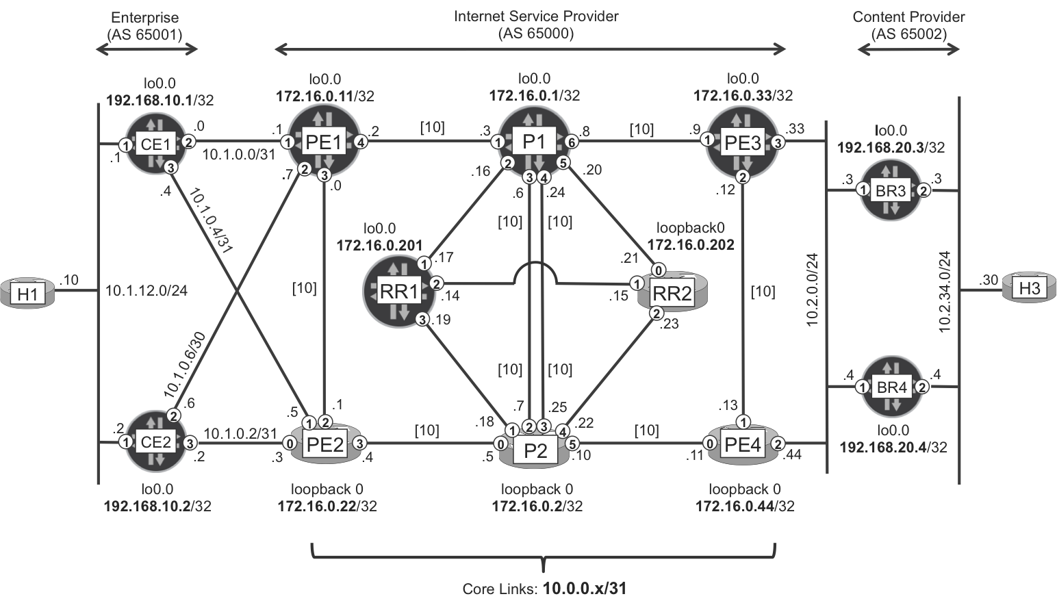
Figure 2-1. Basic MPLS topology
Note
In this chapter, all the IGP core link IS-IS metrics are set to the default value (10). This makes internal load-balancing scenarios more interesting.
LDP
Despite its simple appearance, LDP (RFC 5036) is not that easy to understand. Indeed, LDP can signal three types of transport Label-Switched Paths (LSPs): multipoint-to-point (MP2P), point-to-multipoint (P2MP), and multipoint-to-multipoint (MP2MP). Unlike its fellow RSVP-TE, LDP does not signal the LSP type that happens to be the most intuitive of them all: point-to-point (P2P) LSPs. This chapter focuses on unicast traffic, which in the context of LDP is transported in MP2P LSPs. These go from any ingress provider edge (PE) to a given egress PE. Last but not least, LDP does not implement Traffic Engineering.
So, why is LDP such a popular MPLS transport protocol? Several characteristics make it highly scalable and operationally attractive. First, label signaling takes place on TCP connections, achieving reliable delivery with minimal refresh. Second, MP2P LSPs involve a significant state reduction. And finally, when it comes to configuring transport LSPs, LDP is plug-and-play. You just enable LDP on the core interfaces, and the magic is done.
Example 2-1. LDP configuration at PE1 (Junos)
protocols {
    ldp {
        track-igp-metric;
        interface ge-0/0/3.0;
        interface ge-0/0/4.0;
}}
The track-igp-metric knob couples LDP to the IGP and it is a best practice for loop avoidance. Remember that throughout this entire book, it is assumed that all the MPLS interfaces are declared under [edit protocols mpls] and have family mpls enabled, as in Chapter 1.
Following is a basic LDP configuration in IOS XR.
Example 2-2. LDP configuration at PE2 (IOS XR)
mpls ldp
 interface GigabitEthernet0/0/0/3
 interface GigabitEthernet0/0/0/4
Note
In IOS XR, MPLS often relies on LDP to be globally enabled. If the network runs a different MPLS label signaling protocol, you don’t need to configure any interfaces under mpls ldp, but the global statement is typically needed.
LDP Discovery and LDP Sessions
As soon as LDP is enabled on an interface, a process called basic discovery begins. The LSR begins to send and receive LDP hello messages on each of the configured interfaces. Let’s focus on the message exchange between P1 and P2, which is illustrated in Figure 2-2.
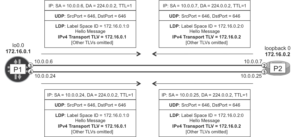
Figure 2-2. LDP hello messages
In the basic discovery process, LDP hello messages are encapsulated as follows:
-
First, in a UDP header, with source and destination port 646
-
Then, in an IPv4 header with TTL=1 and destination address 224.0.0.2, the all-routers link-local multicast address
These packets are not routable, and their purpose is to establish adjacencies between directly connected neighbors only. Note that there is another method called extended discovery, also known as targeted LDP, whereby the LDP hellos are unicast and multihop (TTL>1). This is described later in this chapter.
The basic discovery process builds LDP hello adjacencies. There is one per LDP-enabled interface, so P1 and P2 establish two hello adjacencies.
Example 2-3. LDP hello adjacencies at P1 (Junos)
juniper@P1> show ldp neighbor
Address            Interface          Label space ID      Hold time
10.0.0.2           ge-2/0/1.0         172.16.0.11:0         13
10.0.0.7           ge-2/0/3.0         172.16.0.2:0          12
10.0.0.25          ge-2/0/4.0         172.16.0.2:0          12
10.0.0.9           ge-2/0/6.0         172.16.0.33:0         14
Example 2-4. LDP hello adjacencies at P2 (IOS XR)
RP/0/0/CPU0:P2#show mpls ldp discovery brief

Local LDP Identifier: 172.16.0.2:0

Discovery Source  VRF Name       Peer LDP Id    Holdtime Session
----------------- -------------- -------------- -------- -------
Gi0/0/0/0         default        172.16.0.22:0     15       Y
Gi0/0/0/2         default        172.16.0.1:0      15       Y
Gi0/0/0/3         default        172.16.0.1:0      15       Y
Gi0/0/0/5         default        172.16.0.44:0     15       Y
The LDP hello messages originated by P1 have two key pieces of information:
-
The label space 172.16.0.1:0, whose format is <LSR ID>:<label space ID>. The <LSR ID> is simply P1’s router ID.
But, what do the label space and the transport address stand for?
Let’s begin with the transport address. LDP discovery triggers the establishment of one LDP-over-TCP session between each pair of neighboring LSRs. The endpoints of these multihop TCP sessions are precisely the transport addresses encoded in the UDP-based hellos, as shown in Example 2-5.
Example 2-5. LDP over TCP session (CE1)
juniper@P1> show system connections | match "proto|646"
Proto Recv-Q Send-Q  Local Address   Foreign Address    (state)
tcp4       0      0  172.16.0.1.646  172.16.0.2.51596   ESTABLISHED
tcp4       0      0  172.16.0.1.646  172.16.0.33.50368  ESTABLISHED
tcp4       0      0  172.16.0.1.646  172.16.0.11.49804  ESTABLISHED
tcp4       0      0  *.646           *.*                LISTEN
udp4       0      0  *.646           *.*
It is important to configure the router ID to the same value as a reachable loopback address; otherwise, the LDP session cannot be established.
Note
Even though P1 and P2 have more than one LDP hello adjacency, they only establish one LDP session, from loopback to loopback.
After they establish the TCP connection via the classic three-way handshake, P1 and P2 exchange LDP initialization messages and finally the label information. Let’s have a look at the LDP sessions.
Example 2-6. LDP sessions at P1 (Junos)
juniper@P1> show ldp session
  Address       State        Connection     Hold time  Adv. Mode
172.16.0.2      Operational  Open             24         DU
172.16.0.11     Operational  Open             21         DU
172.16.0.33     Operational  Open             20         DU
Example 2-7. LDP Sessions at P2 (IOS XR)
RP/0/0/CPU0:P2#show mpls ldp neighbor brief

Peer               GR  NSR  Up Time   Discovery  Address  IPv4 Label
-----------------  --  ---  --------- -------    -------  ----------
172.16.0.22:0      N   N    1d04h            1        6          25
172.16.0.44:0      N   N    1d04h            1        5          23
172.16.0.1:0       N   N    00:02:02         2        6          10
The terminology becomes a bit confusing across vendors, so we’ve summarized the concepts. This book uses the RFC terms.
| RFC 5036 | LDP hello adjacencies (UDP) | LDP sessions (TCP) |
|---|---|---|
| Junos | show ldp neighbor |
show ldp session |
| IOS XR | show mpls ldp discovery |
show mpls ldp neighbor |
There are two types of heartbeat mechanisms in LDP:
-
LDP-over-UDP Hello messages to maintain LDP Hello Adjacencies
-
LDP-over-TCP keepalives to maintain LDP Sessions (TCP already provides a keepalive mechanism, but LDP keepalives are more frequent and hence more robust)
LDP Label Mapping
As soon as two neighbors establish an LDP session, they begin to exchange label mapping messages that associate IPv4 prefixes to MPLS labels. These label mappings make up a Label Information Base (LIB).
IPv4 prefixes are one example of Forwarding Equivalence Class (FEC) elements. According to RFC 5036, “The FEC associated with an LSP specifies which packets are ‘mapped’ to that LSP.”
Translated to this chapter’s example topology, PE1 needs an LSP terminated at PE3 in order to send packets beyond PE3. And the FEC associated to that LSP is represented by 172.16.0.33/32, PE3’s loopback address. Although it is not the most precise expression, you could say that 172.16.0.33/32 is a FEC. The ingress PE (in this example, PE1) does not necessarily tunnel traffic destined to the FEC itself. Most typically, the packet matches a route at PE1 whose BGP next hop is 172.16.0.33. This is the association between the packet and the FEC. Good old MPLS logic!
Probably the best way to understand LDP is to see it at work. Let’s focus on one IPv4 prefix or FEC: the loopback address of PE3 (172.16.0.33/32).
In Figure 2-3, you can see that all of the core routers in the network advertise a label mapping for this prefix. This is a bit surprising because PE3 receives from its neighbors label mappings for its own loopback address! As its name implies, LDP is just that, a label distribution protocol, not a routing protocol. It simply distributes label mappings and does not care about whether these announcements make topological sense.
Looking carefully at Figure 2-3, you can see that each router advertises the same label mapping on every LDP session. For example, P1 advertises the mapping [FEC element 172.16.0.33/32, label 300000] to all its neighbors. This is a local label binding at P1. Indeed, P1 locally binds the label 300000 to 172.16.0.33/32, and it’s telling its LDP peers: if you want me to tunnel a packet toward PE3, send it to me with a topmost MPLS header containing label 300000.
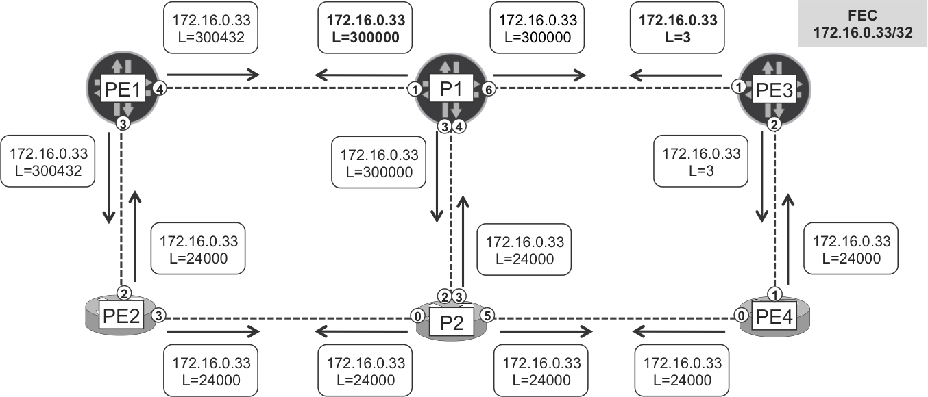
Figure 2-3. LDP label mapping messages for 172.16.0.33
This assignment has only local significance and must be interpreted in the context of label space 172.16.0.1:0. How is the label space decoded? The first field is P1’s router ID, and the second field (zero) translates to a platform label space. What does this mean? Label lookup takes place in P1 regardless of the interface on which the MPLS packet arrives. If P1 receives a packet whose outer MPLS label is 300000, no matter the input interface, P1 will place it on a LSP toward PE3. The mapping (172.16.0.33/32, 3000000) has platform-wide significance within P1.
Note
Both Junos and IOS XR use a platform label space.
RFC 3031 also defines per-interface label spaces, wherein each input interface has its own LIB: an incoming MPLS packet’s label is interpreted in the context of the input interface. Although per-interface label spaces are not implemented, Chapter 21 covers a more generic concept: context-specific label spaces, defined in RFC 5331.
Back to Figure 2-3. Because MPLS labels have local significance, each router typically advertises a different label mapping for a given FEC. However, there is no rule that enforces the labels to be different. For example, PE2, P2, and PE4 happen to all be advertising the same label for 172.16.0.33/32. This is completely fine because each label belongs to a different platform (LSR) label space. It’s a simple coincidence.
Note
LDP label mappings are dynamic and may change upon route flap.
LDP signaling and MPLS forwarding in the Junos plane
Example 2-8 gives us a chance to look at a live demonstration; in this case, a loopback-to-loopback traceroute from CE1 to BR3 traversing the Junos plane (PE1, P1, PE3).
Example 2-8. Traceroute through the Junos LDP plane
juniper@CE1> traceroute 192.168.20.3 source 192.168.10.1
traceroute to 192.168.20.3 (192.168.20.3) from 192.168.10.1 [...]
 1  PE1 (10.1.0.1)  7.962 ms  4.506 ms  5.145 ms
 2  P1 (10.0.0.3)  16.347 ms  10.390 ms  10.131 ms
     MPLS Label=300000 CoS=0 TTL=1 S=1
 3  PE3 (10.0.0.9)  9.755 ms  7.490 ms  7.409 ms
 4  BR3 (192.168.20.3)  8.266 ms  10.196 ms  6.466 ms
Let’s interpret the output step by step. As you saw in Chapter 1, PE1 has a BGP route toward BR3’s loopback, and the BGP next hop of this route is PE3. Then, PE1 resolves this BGP next hop by looking at the inet.3 auxiliary table, and this is how the Internet route (to BR3) gets a labeled forwarding next hop.
Tip
If an IPv4 BGP route does not have a BGP next hop in inet.3, Junos tries to find it in inet.0. You can disable this second lookup and make inet.3 the only resolution Routing Information Base (RIB) for IPv4 routes by using this command: set routing-options resolution rib inet.0 resolution-ribs inet.3
Let’s see the BGP next-hop resolution process in detail.
Example 2-9. MPLS forwarding at ingress PE1 (Junos)
juniper@PE1> show route 192.168.20.3 active-path detail
[...]
                Protocol next hop: 172.16.0.33

juniper@PE1> show route table inet.3 172.16.0.33

inet.3: 9 destinations, 9 routes (9 active, 0 holddown, 0 hidden)
+ = Active Route, - = Last Active, * = Both

172.16.0.33/32     *[LDP/9] 11:00:49, metric 20
                    > to 10.0.0.3 via ge-2/0/4.0, Push 300000

juniper@PE1> show route forwarding-table destination 192.168.20.3
Routing table: default.inet
Internet:
Destination      Type Next hop  Type       Index  NhRef Netif
192.168.20.3/32  user           indr     1048574  3
                      10.0.0.3  Push 300000  593  2     ge-2/0/4.0
Note
This double table lookup takes place only at the control plane. Transit packets are processed according to the forwarding table, which already has the resolved forwarding next hop.
PE1 pushes an MPLS header with label 300000 and sends the packet to the forwarding next hop P1. Why label 300000? The answer is in Figure 2-3 and in Example 2-10. This is the label that P1 maps to FEC 172.16.0.33/32.
Example 2-10. Label Mappings at ingress PE1 (Junos)
juniper@PE1> show ldp database | match "put|172.16.0.33"
Input label database, 172.16.0.11:0--172.16.0.1:0
 300000      172.16.0.33/32
Output label database, 172.16.0.11:0--172.16.0.1:0
 300432      172.16.0.33/32
Input label database, 172.16.0.11:0--172.16.0.22:0
  24000      172.16.0.33/32
Output label database, 172.16.0.11:0--172.16.0.22:0
 300432      172.16.0.33/32
This is an interesting command. It lets you know the label mappings that PE1 is learning (Input label database) and advertising (Output label database). This usage of the input and output keywords is sometimes a bit confusing:
-
The Input label database contains MPLS labels that PE1 must add to a packet when sending it out to a neighbor. This is input for the control or signaling plane (LDP), but output for the forwarding (MPLS) plane.
-
The
Output label databasecontains MPLS labels that PE1 expects to receive from its neighbors. This is output for the control or signaling plane (LDP), but it’s input for the forwarding (MPLS) plane.
After this point is clarified, let’s answer the most important question of this LDP section. If PE1 learns label 300000 from space 172.16.0.1:0, and label 24000 from space 172.16.0.22:0, why is it choosing the first mapping to program the forwarding plane? The answer is on the IGP. Although most of the example topologies in this book use IS-IS, OSPF is an equally valid option and (unless specified otherwise), every statement henceforth applies to IS-IS and OSPF indistinctly.
The shortest path to go from PE1 to PE3 is via P1, so among the several label mappings available for 172.16.0.33/32, PE1 chooses the one advertised by P1. This tight coupling with the IGP is the conceptual key to understanding LDP.
Let’s move on to P1, a pure LSR or P-router.
Example 2-11. LDP signaling and MPLS forwarding at P1 (Junos)
juniper@P1> show ldp database | match "put|172.16.0.33"
Input label database, 172.16.0.1:0--172.16.0.2:0
  24000      172.16.0.33/32
Output label database, 172.16.0.1:0--172.16.0.2:0
 300000      172.16.0.33/32
Input label database, 172.16.0.1:0--172.16.0.11:0
 300432      172.16.0.33/32
Output label database, 172.16.0.1:0--172.16.0.11:0
 300000      172.16.0.33/32
Input label database, 172.16.0.1:0--172.16.0.33:0
      3      172.16.0.33/32
Output label database, 172.16.0.1:0--172.16.0.33:0
 300000      172.16.0.33/32

juniper@P1> show route table mpls.0 label 300000

mpls.0: 12 destinations, 12 routes (12 active, 0 holddown, 0 hidden)
+ = Active Route, - = Last Active, * = Both

300000             *[LDP/9] 00:47:20, metric 10
                    > to 10.0.0.9 via ge-2/0/6.0, Pop
300000(S=0)        *[LDP/9] 00:47:20, metric 10
                    > to 10.0.0.9 via ge-2/0/6.0, Pop

juniper@P1> show route forwarding-table label 300000 table default
Routing table: default.mpls
MPLS:
Destination  Type RtRef Next hop         Index    NhRef Netif
300000       user     0 10.0.0.9   Pop     605     2    ge-2/0/6.0
300000(S=0)  user     0 10.0.0.9   Pop     614     2    ge-2/0/6.0
The IGP tells P1 that the next router in the path toward PE3 is PE3 itself. Naturally! And PE3 maps label 3 to FEC 172.16.0.33/32, its own loopback. This is a reserved label value called implicit null. It is not a real label, but a forwarding instruction that translates to pop the label. In other words, an MPLS packet never carries the label value 3, which is simply a signaling artifact. So, the IPv4 packet arrives unlabeled to PE3, and PE3 has the BGP route to reach BR3. The traceroute trip finishes here. This behavior is called Penultimate Hop Popping (PHP).
There is no label swap operation in a two-hop LSP with PHP. For a longer LSP such as PE1-P1A-P1B-PE3, P1A would perform a label swap.
Note
You can disable PHP and configure explicit null (value 0 for IPv4, value 2 for IPv6), therefore making a real transport MPLS header arrive at the egress PE. One of the applications of explicit null is to keep independent class of service policies for IP and MPLS.
So, is this an LSP? Yes, it is Label-Switched Path; there are MPLS labels after all. But it is signaled in a particular way. The Label Mapping messages depicted in Figure 2-3 allow any router in the network to send MPLS-labeled traffic toward PE3. This is a many-to-one or, in other words, an MP2P LSP.
Let’s finish with a useful toolset described in RFC 4379: MPLS ping and traceroute. These tools don’t require any specific configuration in Junos and they inject UDP-over-IPv4 data packets in an LSP. In that sense, they are very useful to test an LSP’s forwarding plane. The destination IPv4 address of these packets is in the range 127/8, which is reserved for loopback use and is not routable. The appropriate MPLS labels are pushed in order to reach the destination PE, in this case 172.16.0.33. Following is an MPLS traceroute.
Example 2-12. MPLS LDP traceroute (Junos)
juniper@PE1> traceroute mpls ldp 172.16.0.33
  Probe options: ttl 64, retries 3, wait 10, paths 16, exp 7[...]

  ttl    Label  Protocol    Address     Previous Hop   Probe Status
    1   300000  LDP         10.0.0.3    (null)         Success
  FEC-Stack-Sent: LDP
  ttl    Label  Protocol    Address     Previous Hop   Probe Status
    2        3  LDP         10.0.0.9    10.0.0.3       Egress
  FEC-Stack-Sent: LDP

  Path 1 via ge-2/0/4.0 destination 127.0.0.64
LDP signaling and MPLS forwarding in the IOS XR plane
Figure 2-4 presents a similar example, this time focusing on the IOS XR plane (PE2, P2, PE4). The logic is practically identical.
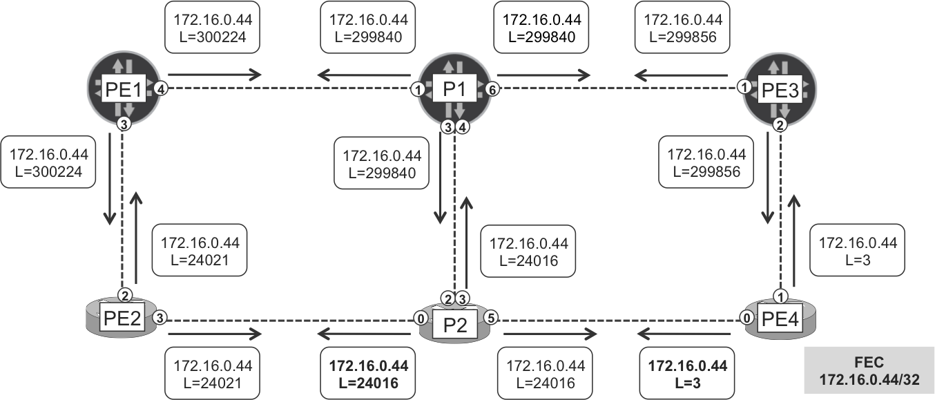
Figure 2-4. LDP label mapping messages for 172.16.0.44
Following is an IPv4 (non MPLS) traceroute from CE2 to BR4.
Example 2-13. Traceroute through the IOS XR Plane
juniper@CE2> traceroute 192.168.20.4 source 192.168.10.2
traceroute to 192.168.20.4 (192.168.20.4) from 192.168.10.2 [...]
 1  PE2 (10.1.0.3)  4.358 ms  2.560 ms  5.822 ms
 2  P2 (10.0.0.5)  9.627 ms  8.049 ms  9.261 ms
     MPLS Label=24016 CoS=0 TTL=1 S=1
 3  PE4 (10.0.0.11)  8.869 ms  7.833 ms  9.193 ms
 4  BR4 (192.168.20.4)  10.627 ms  11.592 ms  11.593 ms
PE2 has a BGP route toward BR4’s loopback, and the BGP next hop of this route is PE4. As is expained in Chapter 1, IOS XR does not have an auxiliary table such as inet.3 in Junos. The actual forwarding is ruled by the Cisco Express Forwarding (CEF) entry for 172.16.0.44/32.
Example 2-14. MPLS forwarding at ingress PE2 (IOS XR)
RP/0/0/CPU0:PE2#show route 192.168.20.4

Routing entry for 192.168.20.4/32
  Known via "bgp 65000", distance 200, metric 0
  Tag 65002, type internal
  Installed Nov 17 08:32:32.941 for 00:30:58
  Routing Descriptor Blocks
    172.16.0.44, from 172.16.0.201
      Route metric is 0
  No advertising protos.

RP/0/0/CPU0:PE2#show cef 172.16.0.44
172.16.0.44/32, version 91, internal [...]
 local adjacency 10.0.0.5
 Prefix Len 32, traffic index 0, precedence n/a, priority 3
   via 10.0.0.5, GigabitEthernet0/0/0/3, 6 dependencies [...]
    path-idx 0 NHID 0x0 [0xa0eb34a4 0x0]
    next hop 10.0.0.5
    local adjacency
     local label 24021      labels imposed {24016}
PE2 pushes an MPLS header with label 24016 and sends the packet to the forwarding next hop P2. Why label 24016? As you can see in Figure 2-4 and in Example 2-15, this is the label that P2 maps to FEC 172.16.0.44/32.
Example 2-15. Label mappings at ingress PE2 (IOS XR)
RP/0/0/CPU0:PE2# show mpls ldp bindings 172.16.0.44/32
172.16.0.44/32, rev 85
        Local binding: label: 24021
        Remote bindings: (2 peers)
            Peer                Label
            -----------------   ---------
            172.16.0.2:0        24016
            172.16.0.11:0       300224
Now, let’s see the LDP signaling and the forwarding state on P2, the next hop LSR.
Example 2-16. LDP signaling and MPLS forwarding at P2 (IOS XR)
RP/0/0/CPU0:P2# show mpls ldp bindings 172.16.0.44/32
172.16.0.44/32, rev 36
        Local binding: label: 24016
        Remote bindings: (3 peers)
            Peer                Label
            -----------------   ---------
            172.16.0.1:0        299840
            172.16.0.22:0       24021
            172.16.0.44:0       ImpNull

RP/0/0/CPU0:P2#show mpls forwarding labels 24016
Local  Outgoing  Prefix         Outgoing   Next Hop     Bytes
Label  Label     or ID          Interface               Switched
------ --------- -------------- ---------- ------------ ----------
24016  Pop       172.16.0.44/32 Gi0/0/0/5  10.0.0.11    379266
Unlike Junos, IOS XR uses MPLS forwarding to reach internal IPv4 prefixes. So, a plain IPv4 traceroute from PE2 to PE4 shows the label, too (although it provides less information than MPLS traceroute).
Example 2-17. IPv4 Traceroute from PE2 to PE4 (IOS XR)
RP/0/0/CPU0:PE2#traceroute ipv4 172.16.0.44
[...]
 1  p2 (10.0.0.5) [MPLS: Label 24016 Exp 0] 9 msec  0 msec  0 msec
 2  pe4 (10.0.0.11) 0 msec  *  0 msec
LDP and Equal-Cost Multipath
According to the IGP metric, there is no single shortest path from PE1 to PE4. Instead, there are four possible equal-cost paths: PE1-PE2-P2-PE4, PE1-P1-PE3-PE4, and two times PE1-P1-P2-PE4 (there are two parallel links between P1 and P2). This condition is called Equal-Cost Multipath (ECMP). With ECMP, each next hop is distinct from a Layer 3 (L3) perspective.
Similarly, a popular technology called Link Aggregation Group (LAG), or Link Bundling, also results in several equal-cost paths. Some common LAG variants are Aggregated Ethernet (AE) and Aggregated SONET (AS). In this case, a single L3 interface can span several physical links that are bundled together. Finally, you can achieve complex equal-cost topologies by combining ECMP and LAG together (e.g., one of the P1-P2 connections could be a LAG).
As soon as there are equal-cost paths to a destination, a natural question arises: which path do the packets follow? Well, they are load balanced, according to a certain logic that is explained later in this section.
Let’s step back for a moment and revisit LDP. Because LDP is coupled to the IGP, it implements ECMP natively. You can check this easily by using MPLS traceroute from PE1 to PE4 (different 127/8 destination IPv4 addresses are automatically used to trigger load balancing); see Example 2-18.
Example 2-18. LDP ECMP (Junos)
juniper@PE1> traceroute mpls ldp 172.16.0.44/32
  Probe options: ttl 64, retries 3, wait 10, paths 16, exp 7 [...]

  ttl    Label  Protocol  Address    Previous Hop   Probe Status
    1    24021  LDP       10.0.0.1   (null)         Success
  FEC-Stack-Sent: LDP
  ttl    Label  Protocol  Address    Previous Hop   Probe Status
    2    24016  Unknown   10.0.0.5   10.0.0.1       Success
  FEC-Stack-Sent: LDP
  ttl    Label  Protocol  Address    Previous Hop   Probe Status
    3        3  Unknown   10.0.0.11  10.0.0.5       Egress
  FEC-Stack-Sent: LDP

  Path 1 via ge-2/0/3.0 destination 127.0.0.64

  ttl    Label  Protocol  Address    Previous Hop   Probe Status
    1   299840  LDP       10.0.0.3   (null)         Success
  FEC-Stack-Sent: LDP
  ttl    Label  Protocol  Address    Previous Hop   Probe Status
    2   299856  LDP       10.0.0.9   10.0.0.3       Success
  FEC-Stack-Sent: LDP
  ttl    Label  Protocol  Address    Previous Hop   Probe Status
    3        3  LDP       10.0.0.13  10.0.0.9       Egress
  FEC-Stack-Sent: LDP

  Path 2 via ge-2/0/4.0 destination 127.0.1.64

  ttl    Label  Protocol  Address    Previous Hop   Probe Status
    2    24016  LDP       10.0.0.25  10.0.0.3       Success
  FEC-Stack-Sent: LDP
  ttl    Label  Protocol  Address    Previous Hop   Probe Status
    3        3  Unknown   10.0.0.11  10.0.0.25      Egress
  FEC-Stack-Sent: LDP

  Path 3 via ge-2/0/4.0 destination 127.0.1.65

  ttl    Label  Protocol  Address    Previous Hop   Probe Status
    2    24016  LDP       10.0.0.7   10.0.0.3       Success
  FEC-Stack-Sent: LDP
  ttl    Label  Protocol  Address    Previous Hop   Probe Status
    3        3  Unknown   10.0.0.11  10.0.0.7       Egress
  FEC-Stack-Sent: LDP

  Path 4 via ge-2/0/4.0 destination 127.0.1.69
Note
You must explicitly enable MPLS Operations, Administration and Management (OAM) in IOS XR by using the global configuration command mpls oam.
The LSP from PE1 to PE4 has four possible equal-cost paths. So, not only the LDP LSPs are MP2P, they are also ECMP-aware. This makes it more challenging to perform fault isolation on very meshed LDP networks.
Here’s what happens from the point of view of a given LSR:
-
When a packet arrives at a specific interface and with a given MPLS label, is it easy to determine the interface to which the LSR will switch the packet out? If there is just one shortest path to the egress PE, it’s easy. But if there is ECMP toward the destination FEC, only advanced vendor-specific tools (beyond the scope of this book) can help to predict the result of the load-balancing decision.
-
When the LSR switches a packet out of an interface with a given MPLS label, it is not easy to guess the previous history of that packet. Which ingress PE did inject it in the MPLS core? At which interface did the packet arrive to the LSR? It is tricky to answer these questions because these LSPs are MP2P and the LDP label space is per platform.
Note that in the previous example, TTL=1 entry for paths 3 and 4 is the same as in path 2; therefore, in the interest of brevity, Junos does not display it. All of these paths traverse P-routers at both planes: Junos (P1) and IOS XR (P2). With the software versions used in this book, MPLS OAM has an interoperability issue that causes the Protocol to be displayed as Unknown. This issue is specific of MPLS OAM only: as far as plain transport LDP is concerned, interoperability is perfect.
In practice, load balancing in LDP networks takes place on a hop-by-hop basis. PE1 has two equal-cost next hops to reach PE4: P1 and PE2. In turn, P1 has three equal-cost next hops to reach PE4: PE3 and twice P2. And so on.
Load-balancing hash algorithm
Load balancing is a complex topic that is intimately related to the hardware implementation of each platform. The good news is that Junos and IOS XR are both capable of doing per-flow load balancing of IP and MPLS traffic. Unlike stateful firewalls, LSRs perform packet-based (not flow-based) forwarding, so what is a flow in the context of a LSR?
A flow is a set of packets with common values in their headers. For example, all the packets of a TCP connection from a client to a server (or of a voice stream between two endpoints), have several fields in common: source and destination address, transport protocol, source and destination ports, and so on. To guarantee that all the packets of a given flow arrive to the destination in the correct order, they should all follow exactly the same path; indirectly, this means that they share respectively the same MPLS label values, hop by hop.
Note
The set of fields that are selected from the packet headers depends on the platform and on the configuration. These fine-tuning details are beyond the scope of this book.
On the other hand, different flows should be evenly distributed across equal-cost next hops such as ECMP, LAG, and so on. Otherwise, some links would not be utilized and others would quickly saturate. This phenomenon is commonly called traffic polarization.
Let’s see how routers achieve per-flow load balancing. For every single packet, the router selects some header fields (plus a fixed local randomization seed) and applies a mathematical algorithm to them called a hash. This algorithm is very sensitive to small variations of its input values. The hash result determines (modulus the number of equal-cost next hops) the actual forwarding next hop to which the packet is mapped. All the packets of a given flow receive the same hash value and are hence forwarded out to the same next hop.
Basic per-flow load balancing is enabled by default in IOS XR, but it requires explicit configuration in Junos, which performs per-destination route hashing by default.
Example 2-19. Enabling per-flow load balancing in Junos
policy-options {
    policy-statement PL-LB {
      then load-balance per-packet;
}}
routing-options {
  forwarding-table export PL-LB;
}
Note
The per-packet syntax remains for historical reasons, but the way it is implemented in modern Junos versions is per-flow (hash based).
Let’s forget for a moment that the topology has two vendor-specific planes. This is a vendor-agnostic analysis of an IP flow from CE1 to BR4:
-
The ingress PE1 receives plain IPv4 packets from CE1 and applies a hash to them. Because all the packets belong to the same flow, the result of the hash is the same and they are all forwarded to the same next hop: P1 or PE2. If the next hop is PE2, there is only one shortest path remaining and the load-balancing discussion stops here.
-
Let’s suppose that the next hop is P1. So, P1 receives MPLS packets and applies a hash to them. This hash takes into account the MPLS label value(s) and it might also consider the inner (e.g., IPv4) headers. As a result, all the packets of this flow are sent out to one and only one of the available next hops: PE3, P2-link1, or P2-link2.
MPLS hash and Entropy Labels
Many LSRs in the industry are able to include MPLS packet payload fields (like IP addresses, TCP/UDP ports) into the load-balancing hash algorithm. But some low-end (or old) platforms from different vendors cannot do that. This can be an issue if the number of active FECs is low. For example, in a domestic Internet Service Provider (ISP) that sends all the upstream traffic up to only two big Internet gateways, most of the packets carry either label L1 (mapped to FEC gateway_1) or label L2 (mapped to FEC gateway_2). Two different label values are clearly not enough to spread traffic across multiple equal-cost paths.
To ensure that there is enough randomness to achieve good load balancing on these devices, RFC 6790 introduces the concept of Entropy Labels. These labels have a per-flow random value and do not have any forwarding significance. In other words, they are not mapped to any FEC. Their goal is just to ensure smooth load balancing along the available equal cost paths. You can read more about Entropy Labels in Chapter 6.
There is a similar technology called Flow-Aware Transport (FAT, RFC 6391), but it is specific of Layer 2 (L2) services. Chapter 6 also covers this in greater detail.
LDP Implementation Details
Although Junos and IOS XR have behaved similarly in the examples so far, their LDP implementation is actually quite different. Let’s follow the LDP advertising flow, starting at the egress PE.
Local FEC label binding/allocation
As shown earlier, PE3 and PE4 both advertise their own loopback mapped to the implicit null label. The following command shows all of the local (or egress) FECs that PE3 and PE4 advertise.
Example 2-20. Default label bindings for local routes (Junos, IOS XR)
juniper@PE3> show ldp database session 172.16.0.44 | match "put|  3"
Input label database, 172.16.0.33:0--172.16.0.44:0
      3      10.0.0.10/31
      3      10.0.0.12/31
      3      10.2.0.0/24
      3      10.255.0.0/16
      3      172.16.0.44/32
Output label database, 172.16.0.33:0--172.16.0.44:0
      3      172.16.0.33/32
The only local FEC that PE3 (Junos) advertises via LDP is its primary lo0.0 address. This is a default behavior that you can change by applying an egress-policy at the [edit protocols ldp] hierarchy. A common use case covered in Chapter 3 is the advertisement of nonprimary lo0.0 IP addresses. Additionally, LDP export policies provide granular per-neighbor FEC advertisement.
On the other hand, PE4 (IOS XR) advertises label mappings for all its directly connected routes by default. Most services use LSPs whose endpoints are loopback addresses, though. In that sense, you can configure IOS XR to do the following:
-
Only advertise /32 FECs by using
mpls ldp address-family ipv4 label local allocate for host-routes -
Granular label binding and advertisement with policies applied at
mpls ldp address-family ipv4 label.
The benefit is a lower amount of state to be kept and exchanged in the LIBs.
What about remote (nonlocal) FECs? By default, both Junos and IOS XR advertise label mappings for IGP routes, regardless of their mask. Again, the previously listed knobs make it possible to change this default behavior.
Label advertisement modes
Figure 2-3 and Figure 2-4 illustrate the Downstream Unsolicited (DU) LDP label advertisement (or distribution) mode that both Junos and IOS XR use by default. This elicits two questions:
-
Why downstream? When it advertises label mapping (300000, 172.16.0.33/32), P1 is telling its neighbors: if you want to use me as a downstream LSR to reach 172.16.0.33/32, send me the packets with this label. So, P1 becomes a potential downstream LSR for that FEC.
-
Why unsolicited? P1’s neighbors do not request any label mappings from P1; however, P1 sends the messages.
Chapter 16 briefly mentions another label distribution method called Downstream on Demand (DoD), which is also used by RSVP-TE.
Label distribution control modes
There are two label distribution control modes: ordered and independent. Junos implements the ordered mode, whereas IOS XR implements the independent mode.
In the ordered mode, the following sequence takes place in strict chronological sequence (see Figure 2-3):
-
PE3 advertises the label mapping (172.16.0.33/32, 3) to its neighbors.
-
P1 receives this label mapping from PE3, the egress LSR, and the shortest-path next hop from P1 to 172.16.0.33 is precisely the direct link P1→PE3.
-
P1 binds label 300000 to this FEC, installs the forwarding entry (300000→ pop to 10.0.0.9) in its Label Forwarding Information Base (LFIB) and advertises the Label Mapping (172.16.0.33/32, 300000) to its neighbors.
-
PE1 receives the label mapping from P1, and the shortest path next hop from PE1 to 172.16.0.33 is precisely P1.
-
PE1 binds label 300432 to the FEC, installs the forwarding entry (300432→ swap 300000 to 10.0.0.3) in its LFIB and advertises the label mapping (172.16.0.33/32, 300432) to its neighbors.
In a nutshell, before binding a label to a remote FEC, Junos LSRs first need to receive a label mapping from the shortest-path downstream LSR en route to the FEC. Likewise, if it loses the downstream labeled state to the FEC (due to an LDP event or to a topology change), after some time the Junos LSR removes the label binding and sends a Label Withdraw message out to its neighbors.
The ordered mode guarantees a strong consistency between the control and the forwarding plane; on the other hand, it requires a potentially higher time to establish the LSPs.
How about independent mode? P2 (IOS XR) binds and announces label mappings regardless of the FEC’s downstream label state.
Suppose that P2 has not established any LDP session yet. Nevertheless, P2 binds labels to local and remote FECs. Then, suppose that the LDP session between P2 and PE2 (and only this session) comes up. At this point, P2 advertises all the label mappings to PE2. These mappings include (172.16.0.33/32, 24000) and (172.16.0.44/32, 24016). As you can see in Example 2-21, the resulting LFIB entries at P2 are marked as Unlabelled.
Example 2-21. Unlabeled bindings in independent mode (IOS XR)
RP/0/0/CPU0:P2#show mpls forwarding
Local  Outgoing    Prefix          Outgoing   Next Hop   Bytes
Label  Label       or ID           Interface             Switched
------ ----------- --------------- ---------- ---------- ---------
[...]
24000  Unlabelled  172.16.0.33/32  Gi0/0/0/2  10.0.0.6   25110
       Unlabelled  172.16.0.33/32  Gi0/0/0/3  10.0.0.24  2664
       Unlabelled  172.16.0.33/32  Gi0/0/0/5  10.0.0.11  2664
24016  Unlabelled  172.16.0.44/32  Gi0/0/0/5  10.0.0.11  134
[...]
What if P2 receives a packet whose outer MPLS label is 24000? The Unlabelled instruction means pop all the labels and forward to the next hop(s) in the LFIB. This is different from the Pop instruction, which just pops the outer label.
The outcome depends on the traffic flows:
-
Internet traffic from CE2 to BR4 successfully reaches its destination.
-
Internet traffic from CE2 to BR3 is forwarded by P2 across three equal-cost next hops. Two of them point to P1, which has no route toward the destination and thus drops the packets.
-
VPN traffic with several labels in the stack might be mapped to the master routing instance (and likely discarded) by the next hop.
When all the LDP sessions come up and P2 receives all the label mapping messages from its neighbors, P2’s LFIB is programmed with the appropriate Swap (to a given label) and Pop instructions.
Example 2-22. Labeled bindings in independent mode (IOS XR)
RP/0/0/CPU0:P2#show mpls forwarding
Local  Outgoing    Prefix          Outgoing   Next Hop   Bytes
Label  Label       or ID           Interface             Switched
------ ----------- --------------- ---------- ---------- ---------
[...]
24000  300000      172.16.0.33/32  Gi0/0/0/2  10.0.0.6   25110
       300000      172.16.0.33/32  Gi0/0/0/3  10.0.0.24  2664
       24000       172.16.0.33/32  Gi0/0/0/5  10.0.0.11  2664
24016  Pop         172.16.0.44/32  Gi0/0/0/5  10.0.0.11  134
[...]
The ordered and independent label distribution control modes are radically different and each has its pros and cons in terms of control and delay. The final state after LDP converges is the same, regardless of the implemented mode.
Label retention modes
Both Junos and IOS XR implement Liberal Label Retention Mode (as opposed to Conservative) by default, meaning that the LSRs accept and store all the incoming label mapping messages. For example, PE1 receives label mappings for FEC 172.16.0.33/32 from both P1 and PE2. Even though the forwarding next hop is P1, PE1 decides to store both label mappings. Why? Potentially, a topology change in the future might turn PE2 into the next hop. Therefore, PE1 keeps all the states, just in case.
FEC aggregation
Looking back at Example 2-20, PE4 advertises five different local FECs to PE3, all of them mapped to the implicit null label. Let’s focus on two of them: 172.16.0.44/32 and 10.0.0.10/31. By default, PE3 advertises them with the same label to P1.
This default behavior in Junos is called FEC aggregation, and you can disable it by configuring set protocols ldp deaggregate. Here is the outcome:
Example 2-23. Default FEC aggregation (Junos)
juniper@PE3> show ldp database | match "put|172.16.0.44|10.0.0.10"
[...]
Output label database, 172.16.0.33:0--172.16.0.1:0
 299856      10.0.0.10/31
 299856      172.16.0.44/32
Input label database, 172.16.0.33:0--172.16.0.44:0
      3      10.0.0.10/31
      3      172.16.0.44/32
Example 2-24. FEC de-aggregation (Junos)
juniper@PE3> show ldp database | match "put|172.16.0.44|10.0.0.10"
[...]
Output label database, 172.16.0.33:0--172.16.0.1:0
 299920      10.0.0.10/31
 299856      172.16.0.44/32
Input label database, 172.16.0.33:0--172.16.0.44:0
      3      10.0.0.10/31
      3      172.16.0.44/32
Note
IOS XR does not perform FEC aggregation by default. In other words, it performs FEC de-aggregation by default.
LDP Inter-Area
Looking back at Figure 2-1, let’s suppose the following:
-
PE1 and PE2 are L2-only IS-IS routers in Area 49.0001.
-
PE3 and PE4 are L1-only IS-IS routers in Area 49.0002.
-
P1 and P2 are IS-IS L1-L2 routers, present in both Areas.
In this scenario, PE3 and PE4 only have a default route to reach PE1 and PE2. And the same would happen with OSPF stub areas. A default route is not specific enough for PE3 and PE4 to process the LDP label mappings for 172.16.0.11/32 and 172.16.0.22/32. This breaks MPLS forwarding.
RFC 5283 proposes a clean solution to this problem, but it is not implemented yet. Is there a workaround? Yes: selective IS-IS L2-to-L1 route leaking, or non-stub OSPF areas. However, this approach has an impact on routing scalability. Chapter 16 covers a clean solution to this challenge, called Seamless MPLS.
Protecting LDP Networks from Traffic Blackholing
Because it is tightly coupled to the IGP but it is not the IGP, plain LDP builds fragile MPLS networks that can easily cause traffic blackholing. Let’s see why, and how to make it more robust.
LDP IGP Synchronization (RFC 5443)
What happens if PE1 and P1 bring up an IS-IS adjacency together, but for whatever reason (routing/filtering issue, misconfiguration, etc.), they do not establish an LDP session to each other? From the point of view of PE1, the shortest path to PE3 is still PE1-P1-PE3. Unfortunately, this path is unlabeled, so P1 discards the customer traffic. In other words, CE1 can no longer ping BR3.
The LDP IGP Synchronization feature increases the IGP metric of a link if LDP is down on it. This way, the network dynamically skips unlabeled links and restores the service. Following is the syntax for IS-IS, which is very similar to the one for OSPF.
Example 2-25. LDP IGP Synchronization in Junos and IOS XR
/* Junos sample configuration */
protocols {
  isis {
     interface ge-0/0/4.0 ldp-synchronization;
 }}

/* IOS XR sample configuration */
router isis mycore
 interface GigabitEthernet0/0/0/3
  address-family ipv4 unicast
   mpls ldp sync
In the following example, the LDP IGP Synchronization feature is turned on for all the network core links, and all the LDP sessions are up except for the one between PE1 and P1. The customer traffic finds its way through a longer yet labeled path. So the end-to-end service is fine.
Example 2-26. LDP IGP Synchronization in action
juniper@PE1> show isis database level 2 PE1.00-00 extensive
[...]
    IS extended neighbor: P1.00, Metric: default 16777214
    IS extended neighbor: PE2.00, Metric: default 10
[...]

juniper@PE1> show isis database level 2 P1.00-00 extensive
[...]
    IS extended neighbor: PE1.00, Metric: default 16777214
    IS extended neighbor: P2.00, Metric: default 10
    IS extended neighbor: P2.00, Metric: default 10
    IS extended neighbor: PE3.00, Metric: default 10
[...]

juniper@CE1> traceroute 192.168.20.3 source 192.168.10.1
traceroute to 192.168.20.3 (192.168.20.3) from 192.168.10.1 [...]
 1  PE1 (10.1.0.1)  7.577 ms  3.113 ms  3.478 ms
 2  PE2 (10.0.0.1)  14.778 ms  13.087 ms  11.303 ms
     MPLS Label=24000 CoS=0 TTL=1 S=1
 3  P2 (10.0.0.5)  11.723 ms  12.630 ms  14.843 ms
     MPLS Label=24000 CoS=0 TTL=1 S=1
 4  P1 (10.0.0.24)  14.599 ms  15.018 ms  23.803 ms
     MPLS Label=300032 CoS=0 TTL=1 S=1
 5  PE3 (10.0.0.9)  13.564 ms  20.615 ms  25.406 ms
 6  BR3 (192.168.20.3)  18.587 ms  15.589 ms  19.322 ms
Both Junos and IOS XR support this feature on IGP interfaces configured as point-to-point, which is the recommended mode for core links. In addition, IOS XR also supports it on broadcast links.
LDP Session Protection
Session Protection is another LDP robustness enhancement, based on the Targeted Hello functionality that is defined on RFC 5036. With this feature, two directly connected LDP peers exchange two kinds of LDP-over-UDP Hello packets:
- LDP Link Hellos
- Single-hop (TTL=1) multicast packets sourced at the link address, destined to 224.0.0.2 and sent independently on each link. These packets achieve basic discovery (see Figure 2-2).
- LDP Targeted Hellos
- Multihop (TTL>1) loopback-to-loopback unicast packets, enabled by using the Session Protection feature.
Note
LDP-over-UDP Targeted Hellos are not the same thing as LDP-over-TCP keepalive messages; they coexist.
LDP Session Protection, as it name implies, maintains the LDP session up upon a link flap. Even if the direct PE1-P1 link goes down, the LDP-over-TCP session and the LDP-over-UDP targeted hello adjacency are both multihop. These packets are routed across the alternate PE1-PE2-P2-P1 path, and in this way the LDP session and the LDP hello adjacency between PE1 and P1 both remain up. The routers keep all the LDP label mappings, which adds forwarding plane robustness to the network.
Let’s look at the configuration and its outcome in Junos:
Example 2-27. LDP Session Protection in Junos (PE1)
protocols {
    ldp {
        interface lo0.0;
        session-protection;
}}

juniper@PE1> show ldp session
  Address           State        Connection  Hold time  Adv. Mode
172.16.0.1          Operational  Open          26         DU
172.16.0.22         Operational  Open          29         DU

juniper@PE1> show ldp neighbor
Address            Interface          Label space ID   Hold time
10.0.0.1           ge-2/0/3.0         172.16.0.22:0      13
10.0.0.3           ge-2/0/4.0         172.16.0.1:0       14
172.16.0.1         lo0.0              172.16.0.1:0       44
172.16.0.22        lo0.0              172.16.0.22:0      41
PE1 does not have parallel links to any neighboring router. So, there are two hello adjacencies to each peer (identified by a common Label space ID): the link hello and the targeted hello adjacency.
Finally, let’s see it on IOS XR:
Example 2-28. LDP Session Protection in IOS XR (PE2)
mpls ldp
 session protection

RP/0/0/CPU0:PE2#show mpls ldp discovery brief

Local LDP Identifier: 172.16.0.22:0

Discovery Source     VRF Name   Peer LDP Id      Holdtime Session
-------------------- ---------- ---------------- -------- -------
Gi0/0/0/2            default    172.16.0.11:0       15       Y
Gi0/0/0/3            default    172.16.0.2:0        15       Y
Tgt:172.16.0.2       default    172.16.0.2:0        90       Y
Tgt:172.16.0.11      default    172.16.0.11:0       45       Y
RSVP-TE
RSVP was initially defined in RFC 2205 as a protocol to make resource reservations along paths in the Internet. Although this original specification did not have much success in terms of industry adoption and real deployments, RSVP was further evolved into the popular RSVP-TE (RFC 3209, Extensions to RSVP for LSP Tunnels), the most flexible and powerful of all the MPLS signaling protocols—which requires more state in the network. Although the TE in the acronym RSVP-TE stands for Traffic Engineering, RSVP-TE has its own place in the MPLS world, and it is a valid deployment choice even for scenarios in which TE is not required. This section covers basic RSVP-TE, and leaves Traffic Engineering to Chapter 13, Chapter 14, and Chapter 15. Very often, this book refers to RSVP-TE simply as RSVP.
RSVP-TE is easier to understand than LDP. It builds two types of LSPs: P2P and P2MP. IP unicast traffic is tunneled in P2P LSPs. Unlike the MP2P LSPs (from-any-to-one) signaled with LDP, RSVP-TE P2P LSPs (from-one-to-one) have a clear head-end. Conceptually, they are very similar to the static LSPs of Chapter 1, except that this time they are dynamically signaled with a protocol: RSVP-TE.
On the other hand, RSVP-TE is not as plug-and-play as LDP. The first necessary (but not sufficient) step is to enable Traffic Engineering in the IGP (IS-IS, in this example) and to configure RSVP on the core interfaces, except for the links to the RRs.
Example 2-29. RSVP-TE configuration at PE1 (Junos)
protocols {
    isis {
        level 2 wide-metrics-only;
    }
    rsvp {
        interface ge-0/0/3.0;
        interface ge-0/0/4.0;
}}
Tip
In Junos, IS-IS Traffic Engineering extensions are turned on by default. OSPF TE extensions require explicit configuration by using the set protocols ospf traffic-engineering command.
Example 2-30. RSVP-TE configuration at PE2 (IOS XR)
1     router isis mycore
2      address-family ipv4 unicast
3       metric-style wide
4       mpls traffic-eng level-2-only
5       mpls traffic-eng router-id Loopback0
6     !
7     rsvp
8      interface GigabitEthernet0/0/0/3
9      interface GigabitEthernet0/0/0/4
10    !
11    mpls traffic-eng
12     interface GigabitEthernet0/0/0/3
13     interface GigabitEthernet0/0/0/4
Note
Lines 7 through 9 are actually not needed for basic RSVP-TE operation, but it is a good practice to add them.
The configuration in Example 2-29 and Example 2-30 does not bring up any RSVP-TE neighbors or LSPs. As you can see in Example 2-31, it just enables the RSVP protocol on the interfaces.
Example 2-31. RSVP-TE baseline state at PE1 and PE2
juniper@PE1> show rsvp neighbor
RSVP neighbor: 0 learned

juniper@PE1> show rsvp interface
RSVP interface: 2 active
                  Active Subscr- Static   Available Reserved[...]
Interface   State resv   iption  BW       BW        BW      [...]
ge-2/0/3.0  Up         0   100%  1000Mbps 1000Mbps  0bps    [...]
ge-2/0/4.0  Up         0   100%  1000Mbps 1000Mbps  0bps    [...]

RP/0/0/CPU0:PE2#show rsvp neighbors
RP/0/0/CPU0:PE2#show rsvp interface

RDM: Default I/F B/W %: 75% [default] (max resv/bc0), 0% [default]

Interface   MaxBW (bps)  MaxFlow (bps) Allocated (bps) MaxSub (bps)
----------- ------------ ------------- --------------- ------------
Gi0/0/0/2             0              0        0 (  0%)       0
Gi0/0/0/3             0              0        0 (  0%)       0
The lack of neighbors is expected. Unlike LDP and IGPs, the role of hello packets in RSVP-TE is quite secondary. RSVP-TE LSPs have their own refresh mechanism and it is not mandatory to have hello adjacencies on the interfaces. RSVP hello adjacencies are typically established when at least one RSVP-TE LSP traverses the link.
RSVP-TE LSP Fundamentals
Unless you use a central controller (see Chapter 15), you need to configure RSVP LSPs explicitly at the ingress PE. There are basically two ways of doing it: defining LSPs one by one, or enabling a certain level of endpoint autodiscovery. Let’s begin with the first approach, which has the advantage of providing more control and flexibility for each individual LSP. Despite its power, the need for manual LSP configuration is one of the reasons why some designers prefer LDP to RSVP, and reserve RSVP for scenarios in which Traffic Engineering is required.
RSVP-TE Tunnels, LSPs, and Sessions
Table 2-2 summarizes the different terminology used by RFC 3209, Junos, and IOS XR.
| RFC 3209 | Tunnel | LSP |
|---|---|---|
| Junos | LSP | Session |
| IOS XR | Tunnel | Path, Session |
In the terms of RFC 3209, you configure tunnels on the ingress PE. A tunnel is incarnated through one or more LSPs. There are several reasons why you may have more than one LSP per tunnel, for example:
-
A tunnel has a primary LSP protected by a standby LSP. This topic is discussed in Chapter 19. This type of tunnel has two persistent LSPs.
-
A tunnel has only one primary LSP but it is being resignaled upon failure, reoptimization, or a change in TE constraints such as bandwidth. In these cases, the tunnel may transitorily have more than one LSP.
You can view an LSP as an incarnation of a tunnel. Two LSPs that belong to the same tunnel share the Tunnel ID value and have a different LSP ID that differentiates them.
In this book, the different vendor terminologies are used and you might see the words tunnel and LSP used in a relatively relaxed and interchangeable manner. This chapter uses the Junos terminology.
RSVP-TE LSP configuration
RSVP-TE LSPs are configured at the head-end (ingress) PE. This makes sense for P2P LSPs, because MPLS LSPs in general—with the exception of MP2MP—are unidirectional. So, even with no specific LSP configuration at PE3 and PE4, Example 2-32 and Example 2-33 are enough to signal the following LSPs.
From PE1 (Junos) to: PE2, PE3, and PE4.
Example 2-32. RSVP-TE LSP configuration at PE1 (Junos)
1     groups {
2         GR-LSP {
3             protocols {
4                 mpls label-switched-path <*> adaptive;
5     }}}
6     protocols {
7         mpls {
8             apply-groups GR-LSP;
9             label-switched-path PE1--->PE2 to 172.16.0.22;
10            label-switched-path PE1--->PE3 to 172.16.0.33;
11            label-switched-path PE1--->PE4 to 172.16.0.44;
12    }}
From PE2 (IOS XR) to: PE1, PE3, and PE4.
Example 2-33. RSVP-TE LSP configuration at PE2 (IOS XR)
group GR-LSP
 interface 'tunnel-te.*'
  ipv4 unnumbered Loopback0
  autoroute announce
  record-route
  path-option 1 dynamic
end-group
!
interface tunnel-te11
 apply-group GR-LSP
 signalled-name PE2--->PE1
 destination 172.16.0.11
!
interface tunnel-te33
 apply-group GR-LSP
 signalled-name PE2--->PE3
 destination 172.16.0.33
!
interface tunnel-te44
 apply-group GR-LSP
 signalled-name PE2--->PE4
 destination 172.16.0.44
Bidirectional end-to-end traffic (such as a successful ping between CE1 and BR3) also requires right-to-left LSPs for the return traffic. As a result, unless another MPLS flavor such as LDP or SPRING is enabled in the core, you also need to configure RSVP-TE LSPs rooted from PE3 and from PE4.
In this way, the network has a full mesh of PE→PE RSVP LSPs.
In “RSVP-TE in Action”, you will see that PE1 (Junos) automatically installs 172.16.0.33/32 in the inet.3 auxiliary table, pointing to LSP PE1--->PE3. On the other hand, PE2 (IOS XR) needs the autoroute announce command to make the CEF entry 172.16.0.44/32 point to interface tunnel-te44 (LSP PE2--->PE4). But this command has more implications, as you can see at the end of Chapter 3.
The Traffic Engineering Database
What happens directly after you configure a RSVP-TE LSP? By default, the ingress PE doesn’t leave anything to fate. It decides in advance the LSP’s exact itinerary by building an ordered list of the hops that the LSP should go through. This list is encoded in an Explicit Route Object (ERO). But where does the ingress PE find the information to compute the ERO? It finds it in the Traffic Engineering Database (TED).
Let’s have a sneak peek on a Junos router’s TED.
Example 2-34. TED at PE1 (Junos)
juniper@PE1> show ted database PE1.00
TED database: 7 ISIS nodes 7 INET nodes
ID                            Type Age(s) LnkIn LnkOut Protocol
PE1.00(172.16.0.11)           Rtr     198     2      2 IS-IS(2)
    To: P1.00(172.16.0.1), Local: 10.0.0.2, Remote: 10.0.0.3
    To: PE2.00(172.16.0.22), Local: 10.0.0.0, Remote: 10.0.0.1

juniper@PE1> show ted database P1.00
TED database: 7 ISIS nodes 7 INET nodes
ID                            Type Age(s) LnkIn LnkOut Protocol
P1.00(172.16.0.1)             Rtr      92     4      4 IS-IS(2)
    To: PE1.00(172.16.0.11), Local: 10.0.0.3, Remote: 10.0.0.2
    To: PE3.00(172.16.0.33), Local: 10.0.0.8, Remote: 10.0.0.9
    To: P2.00(172.16.0.2), Local: 10.0.0.6, Remote: 10.0.0.7
    To: P2.00(172.16.0.2), Local: 10.0.0.24, Remote: 10.0.0.25

juniper@PE1> show ted database PE3.00
TED database: 7 ISIS nodes 7 INET nodes
ID                            Type Age(s) LnkIn LnkOut Protocol
PE3.00(172.16.0.33)           Rtr     133     2      2 IS-IS(2)
    To: P1.00(172.16.0.1), Local: 10.0.0.9, Remote: 10.0.0.8
    To: PE4.00(172.16.0.44), Local: 10.0.0.12, Remote: 10.0.0.13
Similarly, PE2 (IOS XR) also has a TED (Example 2-35).
Example 2-35. TED at PE2 (IOS XR)
RP/0/0/CPU0:PE2#show mpls traffic-eng topology brief 172.16.0.22
[...]
IGP Id: 1720.1600.0022.00, MPLS TE Id: 172.16.0.22 Router Node
  (IS-IS mycore level-2)
  Link[0]:Point-to-Point, Nbr IGP Id:1720.1600.0002.00 [...]
  Link[1]:Point-to-Point, Nbr IGP Id:1720.1600.0011.00 [...]

RP/0/0/CPU0:PE2#show mpls traffic-eng topology brief 172.16.0.2
[...]
IGP Id: 1720.1600.0002.00, MPLS TE Id: 172.16.0.2 Router Node
  (IS-IS mycore level-2)
  Link[0]:Point-to-Point, Nbr IGP Id:1720.1600.0022.00 [...]
  Link[1]:Point-to-Point, Nbr IGP Id:1720.1600.0001.00 [...]
  Link[2]:Point-to-Point, Nbr IGP Id:1720.1600.0001.00 [...]
  Link[3]:Point-to-Point, Nbr IGP Id:1720.1600.0044.00 [...]

RP/0/0/CPU0:PE2#show mpls traffic-eng topology brief 172.16.0.44
[...]
IGP Id: 1720.1600.0044.00, MPLS TE Id: 172.16.0.44 Router Node
  (IS-IS mycore level-2)
  Link[0]:Point-to-Point, Nbr IGP Id:1720.1600.0002.00 [...]
  Link[1]:Point-to-Point, Nbr IGP Id:1720.1600.0033.00 [...]
Note
Although not shown due to the restrictions of space, the TEDs for PE1 and PE2 also contain the nodes from the other vendor’s plane.
The TED looks very much like a Link State Database (LSDB). Indeed, protocols such as IS-IS or OSPF feed the information to build the TED. In addition, both the LSDB and the TED contain per-link Traffic Engineering information that you can see by using the extensive keyword.
Here are the main differences between the IS-IS (or OSPF) LSDB and the TED:
-
The TED is protocol agnostic. It can be populated by IS-IS, OSPF, or even BGP (with a special address family).
-
The TED is unique and there is one separate LSDB per IGP (OSPF, IS-IS) instance or process.
-
The IS-IS (or OSPF) LSDB has information about MPLS and non-MPLS interfaces, whereas the TED only contains MPLS interfaces.
And how can you tell from the LSDB whether a link has MPLS turned on? Let’s temporarily remove family mpls from PE1’s interface ge-2/0/4 (connected to P1). Or, alternatively, delete ge-2/0/4 from protocols rsvp | mpls. Example 2-36 shows PE1’s Link State Packet.
Example 2-36. Link State Packet with MPLS and non-MPLS interfaces (Junos)
juniper@PE1> show isis database PE1 extensive
[...]
  TLVs:
    IS extended neighbor: PE2.00, Metric: default 10
      IP address: 10.0.0.0
      Neighbor's IP address: 10.0.0.1
      Local interface index: 336, Remote interface index: 0
      Current reservable bandwidth:
        Priority 0 : 1000Mbps
        Priority 1 : 1000Mbps
        Priority 2 : 1000Mbps
        Priority 3 : 1000Mbps
        Priority 4 : 1000Mbps
        Priority 5 : 1000Mbps
        Priority 6 : 1000Mbps
        Priority 7 : 1000Mbps
      Maximum reservable bandwidth: 1000Mbps
      Maximum bandwidth: 1000Mbps
      Administrative groups:  0 <none>
    IS extended neighbor: P1.00, Metric: default 10
      IP address: 10.0.0.2
      Neighbor's IP address: 10.0.0.3
      Local interface index: 337, Remote interface index: 0

juniper@PE1> show ted database PE1
TED database: 11 ISIS nodes 7 INET nodes
ID                            Type Age(s) LnkIn LnkOut Protocol
PE1.00(172.16.0.11)           Rtr     601     2      1 IS-IS(2)
    To: PE2.00(172.16.0.22), Local: 10.0.0.0, Remote: 10.0.0.1
      Local interface index: 336, Remote interface index: 0
Note
The acronym LSP can stand for Label-Switched Path or for Link State Packet. In this book, it typically has the first meaning.
Only the MPLS link (PE1-PE2) contains Traffic Engineering sub–Type Length Value (sub-TLVs), and as a result this is the only interface at PE1 that makes it to the TED. Let’s enable MPLS and RSVP on PE1-P1 interface again and move on.
Constrained Shortest-Path First
To compute the ERO for the PE1→PE3 LSP, PE1 runs an algorithm called Constrained Shortest-Path First (CSPF), which finds the best path to PE3 in the TED. Although this book does explore a wide variety of TE constraints later on in Chapter 13 through Chapter 15, the LSPs in Example 2-32 and Example 2-33 are so simple that they impose no constraints at all. And without constraints, CSPF looks very much like the traditional Shortest-Path First (SPF). Here is the outcome of the CSPF calculation that preceded PE1→PE3 LSP’s signaling from PE1:
Example 2-37. CSPF computation for PE1→PE3 LSP (Junos)
juniper@PE1> show rsvp session name PE1--->PE3 detail
[...]
  Explct route: 10.0.0.1 10.0.0.5 10.0.0.24 10.0.0.9
Surprise! The PE1→PE3 LSP is now signaled via PE2, and it has four hops instead of two. Why? Remember that MPLS was temporarily disabled on the PE1→P1 link. This brought down the RSVP-TE LSP and triggered a CSPF computation through a longer alternate path. Yet, now that PE1→P1 is fine again from the point of view of MPLS, why is the LSP still following a longer path?
In both Junos and IOS XR, simple RSVP-TE LSPs tend to avoid flapping links. When they are signaled, RSVP LSPs can remain indefinitely on their current path. If there is a failure (e.g., in one of the path’s links or nodes), the ingress PE runs CSPF again and resignals the LSP.
Thus, the PE1→PE3 LSP has a suboptimal ERO. How can you reoptimize this LSP, or in other words, how can you trigger a CSPF recalculation? Manually flapping a link is not a good idea. There are better ways.
First, you can manually reoptimize an LSP by executing the following operational commands:
-
Junos:
clear mpls lsp name PE1--->PE3 optimize -
IOS XR:
mpls traffic-eng reoptimize 44(tunnel-te 44)
However, this is not scalable from an operational perspective. In both Junos and IOS XR, it is recommended that you configure a reoptimization timer. When the timer expires, the ingress PE runs CSPF again, and if the result is better than the current path, the LSP is resignaled.
Tip
If the network service requirements (latency, bandwidth, etc.) allow it, try to use high timer values. Staying on stable links is a good thing!
You can configure reoptimization timers in Junos either globally or on a per-LSP basis, and they are global in IOS XR. Let’s call this timer T1 (in seconds):
-
Junos:
protocols mpls [label-switched-path <name>] optimize-timer <T1> -
IOS XR:
mpls traffic-eng reoptimize <T1>
LSP optimization takes place in a make-before-break fashion. Before tearing down the original path, PE1 signals a new PE1→PE3 path and gracefully switches the traffic to it. In that sense, the change is not disruptive and does not cause any transit packet loss. In scaled environments, it is wise to delay this switchover, allowing time for the LSP’s forwarding plane to be ready before the routes point to the new path. Let’s call this timer T2 (in seconds):
-
Junos:
protocols mpls optimize-switchover-delay <T2> -
IOS XR:
mpls traffic-eng optimize timers delay installation <T2>
How do T1 and T2 relate to each other? Let’s see an example, by using the Junos terminology from Table 2-2.
The PE1→PE3 LSP is initially mapped to RSVP session A, which follows the shortest IGP path PE1-P1-PE3. Then, the PE1-P1 link experiences a short flap (up→down→up).
Directly after the up→down transition, RSVP session A goes down, and PE1 signals a new RSVP session B through a (longer) available path—for example, PE1-PE2-P2-PE4-PE3. PE1 quickly activates the LSP on RSVP session B and starts timer T1. At this point, the user traffic is restored.
While T1 is ticking down, the link comes back up and IS-IS converges. That’s orthogonal to T1, which just keeps ticking down. When T1 expires, PE1 signals a new RSVP session C through the shortest path PE1-P1-PE3, and starts timer T2.
While T2 is ticking down, PE1 keeps both RSVP sessions B and C up, but the LSP and the user traffic are still on session B. Only when T2 expires, PE1 switches the LSP and the user traffic to session C.
RSVP-TE messages
After the ingress PE computes the ERO, it begins to signal the LSP. Let’s focus on the PE1→PE3 example. As shown in Figure 2-5, the ingress PE (PE1) sends Path messages and the egress PE (PE3) answers with Resv messages. These RSVP messages are encapsulated directly on top of IP (RSVP = IPv4 protocol 46).
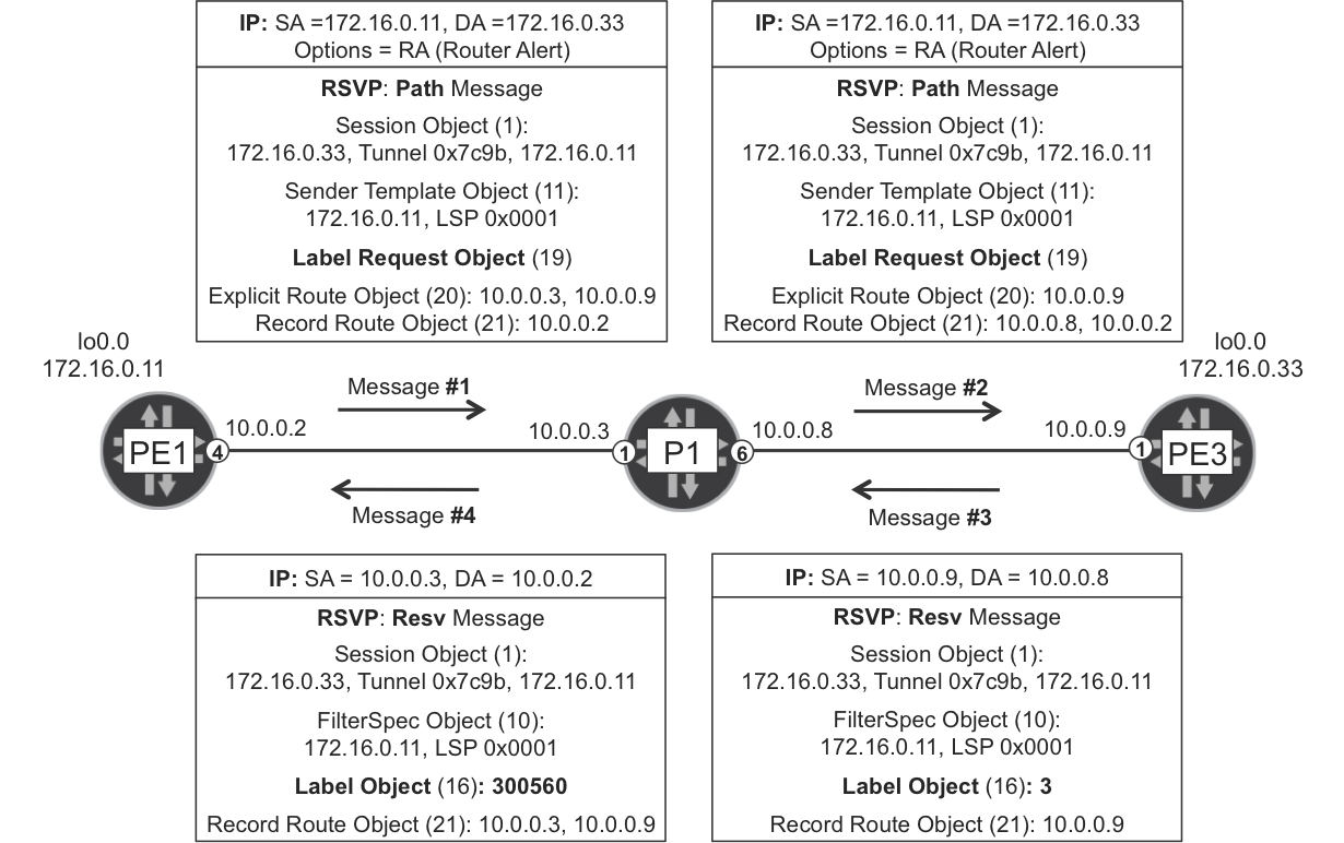
Figure 2-5. RSVP-TE Path and Resv messages
In addition to the ERO, a Path message contains several objects, including the Record Route Object (RRO). The ERO and the RRO have symmetrical roles: whereas the ERO shrinks hop by hop (as there are less hops to go), the RRO grows hop by hop (as there are more hops left behind).
Note
Try to spot the Tunnel ID and the LSP ID in Figure 2-5. When the LSP is resignaled (upon failure, reoptimization, or a change in TE requirements), the Tunnel ID remains the same and the LSP ID is incremented.
RSVP Path messages have a destination IPv4 address equal to the egress PE’s loopback (and not to the transit LSR). For this reason, the ingress PE sets the Router Alert (RA) option in the IPv4 header. This allows the transit LSRs (P1) to intercept and process the Path messages at the control plane, thereby creating dynamic local LSP state and updating both the ERO and the RRO on a hop-by-hop basis.
The Resv messages flow in the opposite direction (upstream) and contain label information. First, the egress PE (PE3) signals the implicit null label; then, the upstream LSRs assign a locally unique label bound to the LSP.
Note
In RSVP-TE, a label is locally bound to an LSP, not to an FEC. If PE1 signals 1,000 LSPs toward PE3 with the same ERO, P1 assigns 1,000 different MPLS labels, one per LSP.
Because Resv messages are triggered by Path messages, RSVP-TE label distribution method is DoD, as compared to the default LDP mode (DU).
RSVP-TE LSPs are maintained by periodic Path/Resv message refresh. This per-LSP message exchange is often called an RSVP session. You can view an RSVP session as a control plane incarnation of an LSP. This is a subtle nuance, so in the RSVP world, the terms LSP and session are often used interchangeably (see Table 2-3).
After it is configured to do so, PE3 also signals a PE3→PE1 LSP by sending Path messages to PE1 and receiving Resv messages from PE1. This enables bidirectional end-to-end traffic.
LSRs send Path and Resv messages periodically in order to keep the RSVP-TE sessions alive. Chapter 16 covers some possible optimizations.
There is also a set of messages (PathErr, PathTear, ResvErr, and ResvTear) that signal LSP error conditions or tear down RSVP-TE LSPs.
RSVP-TE in Action
Let’s see two end-to-end traffic examples, first on the Junos plane (LSP PE1→PE3) and then on the IOS XR plane (PE2→PE4). Figure 2-6 illustrates the RSVP signaling involved in both examples.
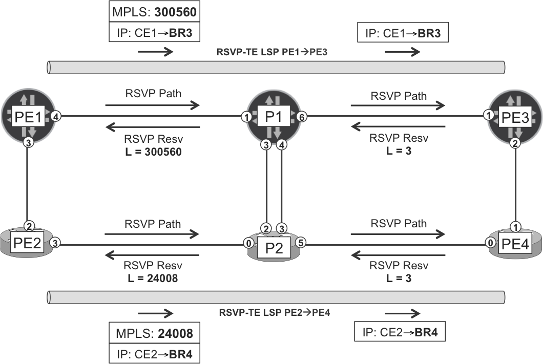
Figure 2-6. RSVP-TE LSPs on Junos and IOS XR planes
RSVP-TE signaling and MPLS forwarding in the Junos plane
The first example (Example 2-38) is a loopback-to-loopback traceroute from CE1 to BR3 traversing the Junos plane (PE1, P1, PE3).
Example 2-38. Traceroute through the Junos plane
juniper@CE1> traceroute 192.168.20.3 source 192.168.10.1
traceroute to 192.168.20.3 (192.168.20.3) from 192.168.10.1 [...]
 1  PE1 (10.1.0.1)  21.468 ms  8.833 ms  4.311 ms
 2  P1 (10.0.0.3)  20.169 ms  33.771 ms  137.208 ms
     MPLS Label=300560 CoS=0 TTL=1 S=1
 3  PE3 (10.0.0.9)  14.305 ms  13.516 ms  12.845 ms
 4  BR3 (192.168.20.3)  23.651 ms  10.378 ms  11.674 ms
Let’s interpret the output step by step. As you saw in Chapter 1, PE1 has a BGP route toward BR3’s loopback, and the BGP next hop of this route is PE3. Then, PE1 resolves this BGP next hop by looking at the inet.3 auxiliary table, and this is how the Internet route (to BR3) gets a labeled forwarding next hop.
Example 2-39. MPLS forwarding at ingress PE1 (Junos)
juniper@PE1> show route 192.168.20.3 active-path detail
[...]
                Protocol next hop: 172.16.0.33

juniper@PE1> show route table inet.3 172.16.0.33

inet.3: 3 destinations, 3 routes (3 active, 0 holddown, 0 hidden)
+ = Active Route, - = Last Active, * = Both

172.16.0.33/32     *[RSVP/7/1] 05:01:26, metric 20
        > to 10.0.0.3 via ge-2/0/4.0, label-switched-path PE1--->PE3

juniper@PE1> show route forwarding-table destination 192.168.20.3
Routing table: default.inet
Internet:
Destination      Type Next hop  Type       Index  NhRef Netif
192.168.20.3/32  user           indr     1048576  2
                      10.0.0.3  Push 300560  595  2     ge-2/0/4.0
PE1 pushes an MPLS header with label 300560 and sends the packet to the forwarding next hop P1. Why label 300560? The answer is in Figure 2-5, Figure 2-6, and Example 2-40: because this is the label that P1 maps to the LSP PE1→PE3.
Example 2-40. RSVP sessions at PE1 (Junos)
juniper@PE1> show rsvp session
Ingress RSVP: 3 sessions
To           From         State Style Labelin Labelout LSPname
172.16.0.22  172.16.0.11  Up       SE       -        3 PE1--->PE2
172.16.0.33  172.16.0.11  Up       FF       -   300560 PE1--->PE3
172.16.0.44  172.16.0.11  Up       SE       -   300256 PE1--->PE4
Total 3 displayed, Up 3, Down 0

Egress RSVP: 3 sessions
To           From         State Style Labelin Labelout LSPname
172.16.0.11  172.16.0.22  Up       SE       3        - PE2--->PE1
172.16.0.11  172.16.0.44  Up       SE       3        - PE4--->PE1
172.16.0.11  172.16.0.33  Up       FF       3        - PE3--->PE1
Total 3 displayed, Up 3, Down 0

Transit RSVP: 2 sessions
To           From         State Style Labelin Labelout LSPname
172.16.0.22  172.16.0.33  Up       SE  299952        3 PE3--->PE2
172.16.0.33  172.16.0.22  Up       SE  299968   300144 PE2--->PE3
Total 2 displayed, Up 2, Down 0

juniper@PE1> show rsvp session name PE1--->PE3 detail
[...]
  PATH sentto: 10.0.0.3 (ge-2/0/4.0) 4226 pkts
  RESV rcvfrom: 10.0.0.3 (ge-2/0/4.0) 4235 pkts[...]
  Explct route: 10.0.0.3 10.0.0.9
  Record route: <self> 10.0.0.3 10.0.0.9
Note
The two first columns in the previous output are To and From. The order is important: first comes the tail-end of the LSP and then the head-end. It’s not always intuitive because the LSPs are signaled the other way around.
From the perspective of PE1, there are three types of RSVP sessions:
-
Ingress RSVP sessions correspond to LSPs originated at PE1 (head-end). They have PE1’s router ID in the second column (
From). -
Egress RSVP sessions correspond to LSPs that terminate at PE1 (tail-end). They have PE1’s router ID in the first column (
To). -
Transit RSVP sessions correspond to LSPs that go through PE1, but whose two endpoints are both outside PE1.
The Style column can show two different values: Shared Explicit (SE) and Fixed Filter (FF). SE is the recommended mode because it makes sure that bandwidth reservations (if any) are not double counted. It is the default in IOS XR and requires explicit configuration in Junos, as you can see in Example 2-32, line 4 (adaptive keyword).
Now, let’s see how to interpret the Labelin and Labelout columns:
-
If PE1 needs to send a packet through LSP PE1→PE3, PE1 pushes label 300560 to the packet before sending it out to the next hop.
-
If PE1 receives an incoming packet with outermost label 299968, PE1 maps the packet to LSP PE2→PE3 and swaps its label to 300144.
-
If PE1 receives an incoming packet with outermost label 299952, PE1 maps the packet to LSP PE3→PE2 and pops the label.
As you can see, RSVP’s Labelin and Labelout are forwarding-plane concepts. MPLS data packets are received by using Labelin and sent by using Labelout. In this sense, show rsvp session and show ldp database have an opposite interpretation of what input and output mean. Indeed, LDP’s input and output label database contain labels learned and advertised, respectively. But MPLS packets flow in the reverse direction!
Back to RSVP: let’s compare two similar (but not identical) commands in Junos.
Example 2-41. RSVP session versus MPLS LSP (Junos)
juniper@PE1> show rsvp session ingress name PE1--->PE3
Ingress RSVP: 3 sessions
To           From         State Style Labelin Labelout LSPname
172.16.0.33  172.16.0.11  Up       FF       -   300560 PE1--->PE3

juniper@PE1> show mpls lsp ingress name PE1--->PE3
Ingress LSP: 3 sessions
To           From         State  P     ActivePath  LSPname
172.16.0.33  172.16.0.11  Up     *                 PE1--->PE3
Total 1 displayed, Up 1, Down 0
If the LSP is up and stable, the first command provides more information (namely, the labels). But, the second command is very useful in other situations: for example, if the LSP cannot be established due to a CSPF failure (no RSVP session), or if the LSP is being reoptimized or it has path protection (two RSVP sessions for the same LSP). These two commands are complementary.
Note
You can see the Tunnel ID by looking at the port number in the show rsvp session extensive output.
Let’s move on to P1, a pure LSR or P-router (Example 2-42).
Example 2-42. RSVP signaling and MPLS forwarding at P1 (Junos)
juniper@PE1> show rsvp session transit name PE1--->PE3
Transit RSVP: 6 sessions
To           From         State Style Labelin Labelout LSPname
172.16.0.33  172.16.0.11  Up       FF  300560        3 PE1--->PE3

juniper@P1> show route forwarding-table label 300560 table default
Routing table: default.mpls
MPLS:
Destination  Type RtRef Next hop         Index    NhRef Netif
300560       user     0 10.0.0.9   Pop     586     2    ge-2/0/6.0
300560(S=0)  user     0 10.0.0.9   Pop     588     2    ge-2/0/6.0
The forwarding table has two routes for label 300560, one for each value of the Bottom of Stack (BoS) bit in the external MPLS header. Which one is relevant for the CE1-to-BR3 traceroute packets? These arrive to P1 with just one MPLS label. In single-label stacks, the Top of Stack (ToS) label is at the same time the BoS label, so the BoS bit is set to 1 (S=1) and the first route applies.
As you saw in the LDP section, label 3 is a reserved label value called implicit null and it translates to pop the label. So, the IPv4 packet arrives unlabeled to PE3, and PE3 has the BGP route to reach BR3.
Let’s wrap up by looking at an RSVP-TE LSP traceroute.
Example 2-43. MPLS RSVP-TE traceroute from PE1 to PE3 (Junos)
juniper@PE1> traceroute mpls rsvp PE1--->PE3
  Probe options: retries 3, exp 7

  ttl    Label  Protocol  Address    Previous Hop   Probe Status
    1   300560  RSVP-TE   10.0.0.3   (null)         Success
  FEC-Stack-Sent: RSVP
  ttl    Label  Protocol  Address    Previous Hop   Probe Status
    2        3  RSVP-TE   10.0.0.9   10.0.0.3       Egress
  FEC-Stack-Sent: RSVP

  Path 1 via ge-2/0/4.0 destination 127.0.0.64
RSVP-TE signaling and MPLS forwarding in the IOS XR plane
Example 2-44 is an end-to-end traceroute from CE2 to BR4 that goes through the IOS XR plane (PE2, P2, PE4).
Example 2-44. Traceroute through the IOS XR plane
juniper@CE2> traceroute 192.168.20.4 source 192.168.10.2
traceroute to 192.168.20.4 (192.168.20.4) from 192.168.10.2 [...]
 1  PE2 (10.1.0.3)  2.833 ms  3.041 ms  2.441 ms
 2  P2 (10.0.0.5)  10.465 ms  8.480 ms  9.311 ms
     MPLS Label=24008 CoS=0 TTL=1 S=1
 3  PE4 (10.0.0.11)  8.461 ms  8.757 ms  7.982 ms
 4  BR4 (192.168.20.4)  9.109 ms  10.427 ms  9.248 ms
PE2 has a BGP route toward BR4’s loopback, and the BGP next hop of this route is PE4. The key here is the CEF entry for 172.16.0.44/32. Let’s have a look at it.
Example 2-45. MPLS forwarding at ingress PE2 (IOS XR)
1     RP/0/0/CPU0:PE2#show cef 172.16.0.44
2     172.16.0.44/32, version 91, internal [...]
3      local adjacency 10.0.0.5
4      Prefix Len 32, traffic index 0, precedence n/a, priority 1
5        via 172.16.0.44, tunnel-te44, 4 dependencies [...]
6         path-idx 0 NHID 0x0 [0xa0db3250 0x0]
7         next hop 172.16.0.44
8         local adjacency
9          local label 24016      labels imposed {ImplNull}
The label operation for this LSP is as follows: push a real label, not implicit null. The real label does not show in line 9. Actually, seeing ImplNull there is a sign that everything is OK.
What is tunnel-te44? This is an explicitly configured interface, and it pushes an MPLS label with a value (24008) that matches traceroute’s output, as shown in Example 2-44 and in Example 2-46 (line 7):
Example 2-46. RSVP-TE LSP at PE2 (IOS XR)
1     RP/0/0/CPU0:PE2#show mpls traffic-eng tunnels name tunnel-te44 detail
2     Name: tunnel-te44  Destination: 172.16.0.44  Ifhandle:0x580
3       Signalled-Name: PE2--->PE4
4       Status:
5         Admin:    up Oper:   up   Path:  valid   Signalling: connected
6     [...]
7         Outgoing Interface: GigabitEthernet0/0/0/3, Outgoing Label: 24008
8         Path Info:
9           Outgoing:
10            Explicit Route:
11              Strict, 10.0.0.5
12              Strict, 10.0.0.11
13              Strict, 172.16.0.44
14        Resv Info:
15          Record Route:
16            IPv4 10.0.0.5, flags 0x0
17            IPv4 10.0.0.11, flags 0x0
18
19    RP/0/0/CPU0:PE2#show rsvp session tunnel-name PE2--->PE4
20    Type Destination Add DPort  Proto/ExtTunID  PSBs  RSBs  Reqs
21    ---- --------------- ----- --------------- ----- ----- -----
22    LSP4     172.16.0.44    44     172.16.0.22     1     1     0
Now, let’s look at the RSVP-TE session and forwarding entries on P2, the next hop LSR.
Example 2-47. RSVP signaling and MPLS forwarding at P2 (IOS XR)
RP/0/0/CPU0:P2#show rsvp session tunnel-name PE2--->PE4 detail
SESSION: IPv4-LSP Addr: 172.16.0.44, TunID: 44, ExtID: 172.16.0.22
 Tunnel Name: PE2--->PE4 [...]
  RSVP Path Info:
   InLabel: GigabitEthernet0/0/0/0, 24008
   Incoming Address: 10.0.0.5
   Explicit Route:
     Strict, 10.0.0.5/32
     Strict, 10.0.0.11/32
     Strict, 172.16.0.44/32
   Record Route:
     IPv4 10.0.0.4, flags 0x0
   Tspec: avg rate=0, burst=1K, peak rate=0
  RSVP Resv Info:
   OutLabel: GigabitEthernet0/0/0/5, 3
   FRR OutLabel: No intf, No label
   Record Route:
     IPv4 10.0.0.11, flags 0x0

RP/0/0/CPU0:P2#show mpls forwarding labels 24008
Wed Nov 26 10:58:09.822 UTC
Local  Outgoing    Prefix     Outgoing     Next Hop   Bytes
Label  Label       or ID      Interface               Switched
------ ----------- ---------- ------------ ---------- --------
24008  Pop         44         Gi0/0/0/5    10.0.0.11  192900
And finally, following is an example of RSVP-TE LSP traceroute in IOS XR.
Example 2-48. MPLS RSVP-TE traceroute from PE2 to PE4 (IOS XR)
RP/0/0/CPU0:PE2#traceroute mpls traffic-eng tunnel-te 44

[...]
  0 10.0.0.4 MRU 1500 [Labels: 24008 Exp: 0]
L 1 10.0.0.5 MRU 1500 [Labels: implicit-null Exp: 0] 0 ms
! 2 10.0.0.11 1 ms     IPv4 10.0.0.4, flags 0x0
Note
Remember that MPLS OAM requires explicit configuration in IOS XR.
RSVP-Constrained Paths and ECMP
RSVP-TE EROs determine the path of an LSP univocally. There is no load balancing inside an LSP: after it is established, the LSP follows one—and only one—path until the LSP is resignaled and moves to another single path. This makes RSVP-TE less ECMP-aware than LDP. Let’s see how to achieve load balancing with plain RSVP-TE LSPs: you basically need several LSPs between the same head and tail.
Following is a Junos configuration with three RSVP-TE LSPs from PE1 to PE4.
Example 2-49. Three RSVP-TE LSPs from PE1 to PE4 (Junos)
protocols {
    mpls {
        label-switched-path PE1--->PE4 to 172.16.0.44;
        label-switched-path PE1--->PE4-A {
            to 172.16.0.44;
            primary PE4-A;
        }
        label-switched-path PE1--->PE4-B {
            to 172.16.0.44;
            primary PE4-B;
        }
        path PE4-A {
            10.0.0.3 strict;
            10.0.0.7 strict;
            10.0.0.11 strict;
        }
        path PE4-B {
            172.16.0.22 loose;
}}}
This configuration brings up three LSPs:
-
PE1→PE4 does not have any CSPF constraints. PE1 chooses an ERO among the four available equal-cost paths to PE4, and the result is not deterministic.
-
PE1→PE4-A has strict CSPF constraints: an ordered list of forwarding next hops. This is actually a manually configured ERO and it leaves CSPF with only one option. Hence, the path is deterministic.
-
PE1→PE4-B has a loose CSPF constraint: go via PE2. It is loose because it does not specify how to enter or exit PE2. However, there is only one possible path that meets the constraint in this topology.
PE1 load balances across the three LSPs, regardless of their path.
Example 2-50. RSVP-TE ECMP from PE1 to PE4 (Junos)
1     juniper@PE1> show rsvp session ingress name PE1--->PE4* extensive
2     [...]
3       LSPname: PE1--->PE4, LSPpath: Primary
4       Resv style: 1 SE, Label in: -, Label out: 300576
5       Explct route: 10.0.0.3 10.0.0.9 10.0.0.13
6      [...]
7       LSPname: PE1--->PE4-A, LSPpath: Primary
8       Resv style: 1 SE, Label in: -, Label out: 300560
9       Explct route: 10.0.0.3 10.0.0.7 10.0.0.11
10     [...]
11      LSPname: PE1--->PE4-B, LSPpath: Primary
12      Resv style: 1 SE, Label in: -, Label out: 24003
13      Explct route: 10.0.0.1 10.0.0.5 10.0.0.11
14
15    juniper@PE1> show route table inet.3 172.16.0.44
16
17    inet.3: 3 destinations, 3 routes (3 active, 0 holddown, 0 hidden)
18    + = Active Route, - = Last Active, * = Both
19
20    172.16.0.44/32     *[RSVP/7/1] 11:44:37, metric 30
21       > to 10.0.0.3 via ge-2/0/4.0, label-switched-path PE1--->PE4
22         to 10.0.0.3 via ge-2/0/4.0, label-switched-path PE1--->PE4-A
23         to 10.0.0.1 via ge-2/0/3.0, label-switched-path PE1--->PE4-B
24
25    juniper@PE1> show route forwarding-table destination 192.168.20.4
26    Routing table: default.inet
27    Internet:
28    Destination      Type Next hop        Type  Index    Netif
29    192.168.20.4/32  user                 indr  1048577
30                                          ulst  1048581
31                          10.0.0.3 Push 300576      596  ge-2/0/4.0
32                          10.0.0.3 Push 300560      599  ge-2/0/4.0
33                          10.0.0.1 Push 24003       597  ge-2/0/3.0
As you can see, the ingress PE actually expands the 172.16.0.22 loose next hop into a list of strict next hops (lines 5, 9, and 13). In this case, loose and strict are local properties, only meaningful in the context of CSPF. The resulting ERO has a simpler structure: it’s just a list of IPv4 next hops.
Note
In some cases, the RSVP-TE Path messages may actually include loose next hops. This is the case of inter-area scenarios where the ingress PE signals a loose next hop and the ABR expands it into a list of strict next hops.
If the manually defined path is not valid or it has loops, CSPF fails and the ingress PE does not signal the LSP. In addition, RSVP-TE has a mechanism (based on the RRO) to detect loops in transit during LSP establishment.
Load balancing is achieved with a unilist next hop (line 30). Although not shown in Example 2-50, all the unicast next hops (lines 31 through 33) have weight 0x1. This topic is fully explained in Chapter 20.
Note that after a packet enters a given RSVP-TE LSP, there is just one possible path ahead. All of the load balancing is performed at the head-end, unlike LDP LSPs for which ECMP happens in a hop-by-hop basis.
The load-balancing scheme illustrated in Example 2-50 and in Figure 2-7 is imperfect: one of the P1-P2 links is not utilized and the PE1-P1 link is loaded two more times than the PE1-PE2 link. As the network grows more complex, it’s virtually impossible to achieve decent load balancing with this manual approach. Fortunately, this challenge can be addressed with container LSPs (Chapter 14) and/or external controllers (Chapter 15).
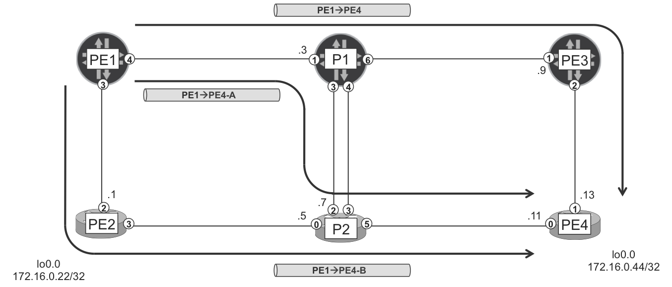
Figure 2-7. Three RSVP-TE LSPs from PE1 to PE4
What if a transit link fails? If the currently active path of PE1→PE4 were affected, the LSP would be resignaled successfully through a different path. But PE1→PE4-A (like PE1→PE4-B) does not have this flexibility and it would fail—see the fast restoration (Chapter 18 through Chapter 21) for protection features.
Now let’s discuss a different example. Suppose that PE1 has two LSPs toward PE3 (not PE4). These two LSPs follow the paths (PE1, P1, PE3) and (PE1, PE2, P2, PE4, PE3), respectively. Obviously, the second path is longer and has a higher cumulative metric. However, PE1 load-balances flows across the two LSPs. Why?
Note
By default in Junos and IOS XR, the metric of a RSVP-TE LSP is equal to the IGP shortest-path metric to the destination. This is regardless of the actual path followed by the LSP: only the endpoints matter.
Let’s finish up the ECMP discussion by looking at Example 2-51, which is based on IOS XR. In this case, PE2 signals several LSPs toward PE3.
Example 2-51. Two RSVP-TE LSPs from PE2 to PE3 (IOS XR)
group GR-LSP-NO-PATH
 interface 'tunnel-te.*'
  ipv4 unnumbered Loopback0
  autoroute announce
  record-route
end-group
!
interface tunnel-te33
 apply-group GR-LSP-NO-PATH
 signalled-name PE2--->PE3
 destination 172.16.0.33
 path-option 1 dynamic
!
interface tunnel-te330
 apply-group GR-LSP-NO-PATH
 signalled-name PE2--->PE3-A
 destination 172.16.0.33
 path-option 1 explicit name PE3-A
!
explicit-path name PE3-A
 index 10 next-address strict ipv4 unicast 10.0.0.5
 index 20 next-address loose ipv4 unicast 172.16.0.44
As expected, the PE2→PE3-A path follows the path specified, and PE2 load-balances PE2-to-PE3 traffic between the two LSPs (Example 2-52).
Example 2-52. RSVP-TE ECMP from PE2 to PE3 (IOS XR)
RP/0/0/CPU0:PE2#show rsvp session tunnel-name PE2--->PE3 detail
[...]
   Explicit Route:
     Strict, 10.0.0.0/32
     Strict, 10.0.0.3/32
     Strict, 10.0.0.9/32
     Strict, 172.16.0.33/32

RP/0/0/CPU0:PE2#show rsvp session tunnel-name PE2--->PE3-A detail
[...]
   Explicit Route:
     Strict, 10.0.0.5/32
     Strict, 10.0.0.11/32
     Strict, 172.16.0.44/32

RP/0/0/CPU0:PE2#show cef 172.16.0.33
172.16.0.33/32, version 829, internal [...]
 Updated Nov 29 10:35:04.150
 Prefix Len 32, traffic index 0, precedence n/a, priority 1
   via 172.16.0.33, tunnel-te33, 4 dependencies [...]
    path-idx 0 NHID 0x0 [0xa0db3638 0x0]
    next hop 172.16.0.33
    local adjacency
   via 172.16.0.33, tunnel-te330, 4 dependencies [...]
    path-idx 1 NHID 0x0 [0xa0db3250 0x0]
    next hop 172.16.0.33
    local adjacency
Like Junos, IOS XR decouples the load-balancing decision from the actual path followed by the LSP. If PE2 has several paths to PE4, for example (PE2, P2, PE4) and (PE2, PE1, P1, PE3, PE4), PE2 spreads traffic flows between both LSPs, even if one path is much longer than the other.
Inter-Area RSVP-TE LSPs
RFC 4105 defines a set of requirements on inter-area RSVP-TE LSPs.
Looking back at Figure 2-1, let’s suppose the following:
-
PE1 and PE2 are L2-only IS-IS routers in Area 49.0001
-
PE3 and PE4 are L1-only IS-IS routers in Area 49.0002
-
P1 and P2 are IS-IS L1-L2 routers, present in both Areas
In this scenario, the link-state information is fragmented so that only P1 and P2 have a complete TED. On the other hand, a PE’s TED only contains links of the local area. This makes it impossible for PE1 or PE2 to compute an ERO to reach PE3 or PE4, and vice versa. And a similar situation would occur with OSPF, too.
Route redistribution (such as IS-IS L2-to-L1 route leaking) does not propagate topology information, so it doesn’t solve the issue. There are two clean solutions:
-
BGP-LS (covered in Chapter 15) solves the issue by propagating interdomain topology information.
-
Segmented and Hierarchical LSPs (Chapter 9 and Chapter 16) relax the need for inter-area RSVP-TE LSPs.
Let’s now see a quick but limited approach to get the inter-area RSVP-TE LSPs up and running. It’s the third (and less preferred) solution.
Although by default Junos and IOS XR compute a complete ERO and include it in Path messages, in reality this is not mandatory. The ERO is an optional object, and CSPF is optional, too. If you configure the PE3→PE1 LSP with the no-cspf option in Junos, PE3 simply looks for the best IGP route to PE1. It sends the Path message with no ERO to the next-hop LSR and waits for a Resv message. This actually works fine, but PE3 has no control on the path beyond the first next hop, which is clearly a challenge if you want to use Traffic Engineering constraints.
As an administrator, you can actually influence the LSP’s itinerary within the local area of the ingress PE. For example, PE3 can choose the path that PE3→PE1 takes within area 49.0002. This can be useful to select the path toward the ABR, but there is no control beyond the ABR because there is no end-to-end visibility of the TED.
Likewise, the following IOS XR configuration results in an inter-area PE4→PE1 LSP successfully signaled end to end.
Example 2-53. Inter-area RSVP-TE LSP signaled from PE4 (IOS XR)
group GR-LSP-PATH
 interface 'tunnel-te.*'
  ipv4 unnumbered Loopback0
  record-route
end-group
!
interface tunnel-te11
 apply-group GR-LSP-PATH
 signalled-name PE4--->PE1
 destination 172.16.0.11
 path-option 1 explicit name PE1-A
!
explicit-path name PE1-A
 index 10 next-address loose ipv4 unicast 172.16.0.2
!
router static
 address-family ipv4 unicast
  172.16.0.11/32 tunnel-te11
The static route is necessary because IOS XR only supports autoroute announce in single-domain LSPs. You must configure it so that the CEF entry for 172.16.0.11/32 points to the tunnel interface.
RSVP Auto Tunnel
When it comes to RSVP-TE LSPs, there is much confusion around the words static and dynamic. In this book, RSVP-TE is always considered to be dynamic. Chapter 1 presents an example of static (protocol-less) LSPs. But RSVP-TE is a dynamic protocol that signals LSPs end to end, detects and reacts upon failures, and so on. This remains true even if the LSP has a statically configured ERO.
RSVP Auto Tunnel (or Dynamic Tunnels) brings endpoint autodiscovery to the table. Instead of having to explicitly configure LSPs one by one, you let the ingress PE do the job of discovering remote PEs and automatically building LSPs toward them. It is still possible to apply Traffic Engineering constraints to these LSPs via a template, but you can no longer specify strict or loose IPv4 paths. So, RSVP Auto Tunnel is a time saver, but it has a cost: less control and less granularity.
The following example presents RSVP Auto Tunnel in Junos (PE1).
Example 2-54. RSVP-TE Auto Tunnel at PE1 (Junos)
routing-options {
    dynamic-tunnels {
        TN-PE1 {
            rsvp-te LOOPBACKS {
                label-switched-path-template default-template;
                destination-networks 172.16.0.0/16;
}}}}

juniper@PE1> show rsvp session ingress
Ingress RSVP: 3 sessions
To           From         State Labelout LSPname
172.16.0.22  172.16.0.11  Up           3 172.16.0.22:dt-rsvp-TN-PE1
172.16.0.33  172.16.0.11  Up      300512 172.16.0.33:dt-rsvp-TN-PE1
172.16.0.44  172.16.0.11  Up      300608 172.16.0.44:dt-rsvp-TN-PE1
Total 3 displayed, Up 3, Down 0
There is no LSP toward P1 and P2. So, why does PE1 only signal LSPs toward the PEs? The P-routers are not advertising any BGP route, so PE1 does not need to resolve the BGP next hops 172.16.0.1 and 172.16.0.2. This is a resource-saving strategy: PE1 signals only the LSPs it needs.
Finally, let’s see the Auto Tunnel feature in IOS XR (PE2).
Example 2-55. RSVP-TE Auto Tunnel at PE2 (IOS XR)
ipv4 unnumbered mpls traffic-eng Loopback0
!
ipv4 prefix-list PR-TUNNEL
 10 deny 172.16.0.0/30 eq 32        # No tunnels to P1 and P2
 20 permit 172.16.0.0/26 eq 32
!
mpls traffic-eng
  auto-tunnel mesh
    group 1
      attribute-set AT-MESH
      destination-list PR-TUNNEL
    tunnel-id min 10 max 20
  attribute-set auto-mesh AT-MESH
    autoroute announce

RP/0/0/CPU0:PE2#  show mpls traffic-eng tunnels brief

         TUNNEL NAME         DESTINATION      STATUS  STATE
        +tunnel-te10         172.16.0.11          up  up
        +tunnel-te11         172.16.0.33          up  up
        +tunnel-te12         172.16.0.44          up  up
   autom_PE4_t12_mg1         172.16.0.22          up  up
  172.16.0.22:dt-rsv         172.16.0.22          up  up
  172.16.0.22:dt-rsv         172.16.0.22          up  up
+ = automatically created mesh tunnel
The Auto Tunnel LSPs signaled to PE2 from PE1, PE3 and PE4 are: 172.16.0.22:dt-rsvp-TN-PE1, 172.16.0.22:dt-rsvp-TN-PE3 and autom_PE4_t12_mg1, respectively.
IGP and SPRING
Source Packet Routing in Networking (SPRING), also known as Segment Routing (SR), is a recent network routing paradigm covered by several complementary IETF drafts at the time of publication of this book. The most fundamental are draft-ietf-spring-segment-routing, draft-ietf-spring-segment-routing-mpls, draft-ietf-isis-segment-routing-extensions, and draft-ietf-ospf-segment-routing-extensions.
SPRING is proposed as an alternative to LDP and/or RSVP-TE:
-
As an LDP alternative, SPRING is natively implemented by the IGP (IS-IS or OSPF), so it reduces the number of protocols running in the network.
-
As an RSVP-TE alternative, SPRING natively supports ECMP and implements a more scalable control plane because it does not need to keep per-LSP state in the network. On the other hand, SPRING does not have bandwidth reservation mechanisms, so if this function is required, you can achieve it only with the help of a central controller.
SPRING initial use cases are Traffic Engineering (see Chapter 16) and fast restoration (see Chapter 18), but new applications are being defined.
You might be venturing a guess that SPRING uses source routing as a means to transport packets from one PE to another PE across the core. However, this is not always the case. Strikingly, the SPRING technology applied to this chapter’s basic transport scenario can be explained without invoking the source routing concept at all. Indeed, this first example’s SPRING LSP’s are MP2P and have only one segment. This chapter later explains what the “Source Packet Routing” in SPRING and the “Segment” in SR actually stand for.
For the moment, you can think of a segment as an instruction. On the wire, a segment is either encoded into a MPLS header or into something else (the alternatives are explained later in this section). Following is a first classification of segments, assuming that the forwarding plane is MPLS-based. Unlike labels, which are always local (see RFC 3031), segments can either be local or global.
-
Local segments
The router that originates and advertises a local segment is the only one that assigns a label to the segment and installs that label in its LFIB.
- Global segments
Typically every router in the domain assigns a (local) label to a (global) segment and installs that label in its LFIB.
SPRING in Action
One of the most important components of SPRING is its ability to advertise MPLS label information in the IGP, in the form of IS-IS sub-TLVs or new opaque OSPF LSAs. Let’s see it in detail for IS-IS.
This is a basic SPRING configuration in Junos (PE1).
Example 2-56. SPRING configuration at PE1 (Junos)
protocols {
    isis {
        source-packet-routing {
            node-segment ipv4-index 11;
And here it is in IOS XR (PE2).
Example 2-57. SPRING configuration at PE2 (IOS XR)
router isis mycore
 address-family ipv4 unicast
  segment-routing mpls
 !
 interface Loopback0
  address-family ipv4 unicast
   prefix-sid index 22
This configuration leads to the automatic creation of MP2P LSPs (any-to-PE1 and any-to-PE2), topologically identical to the ones signaled by LDP. SPRING is easier to understand when the LSPs have at least two hops on each (Junos, IOS XR) plane. The links PE1-P1 and P2-PE4 are temporarily disabled to achieve the forwarding path shown in Example 2-58 and in Figure 2-8.
Example 2-58. Traceroute from CE1 to BR4
juniper@CE1> traceroute 192.168.20.4 source 192.168.10.1
traceroute to 192.168.20.4 (192.168.20.4) from 192.168.10.1 [...]
 1  PE1 (10.1.0.1)  33.591 ms  9.484 ms  3.845 ms
 2  PE2 (10.0.0.1)  45.782 ms  11.524 ms  16.886 ms
     MPLS Label=16044 CoS=0 TTL=1 S=1
 3  P2 (10.0.0.5)  11.891 ms  11.991 ms  13.639 ms
     MPLS Label=16044 CoS=0 TTL=1 S=1
 4  10.0.0.24 (10.0.0.24)  13.205 ms  15.812 ms  16.886 ms
     MPLS Label=800044 CoS=0 TTL=1 S=1
 5  PE3 (10.0.0.9)  21.226 ms  15.272 ms  18.900 ms
     MPLS Label=800044 CoS=0 TTL=1 S=1
 6  PE4 (10.0.0.13)  19.875 ms  15.498 ms  21.145 ms
 7  BR4 (192.168.20.4)  15.067 ms  21.923 ms  21.952 ms
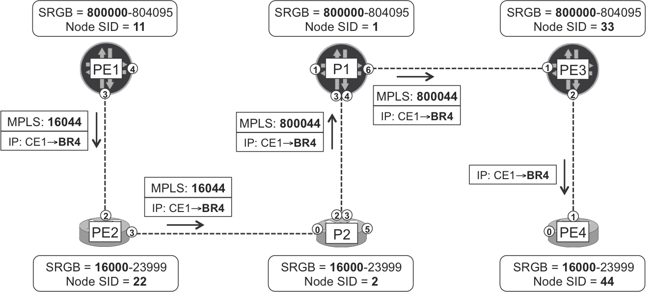
Figure 2-8. SPRING tunnel from PE1 to PE4
Interestingly, all the labels end in 44, the Node Segment Identifier (Node SID) of PE4. And, there are only two different label values in the flow: 16044 and 800044. Actually, if the path had 10 times more next hops, there would still be only two label values (one for Junos, one for IOS XR). This is totally different from LDP and RSVP, whose labels are not deterministic and often change to a different value over time and on a hop-by-hop basis.
But, where do these labels come from? Every LSR in the path adds new sub-TLVs to their own IS-IS node Link State Packet.
Example 2-59. SPRING sub-TLVs in IS-IS Link State Packets
RP/0/0/CPU0:PE2# show isis database verbose

IS-IS mycore (Level-2) Link State Database
LSPID           LSP Seq Num  LSP Checksum  LSP Holdtime  ATT/P/OL
P1.00-00        0x00000645   0xdde2        472             0/0/0
  Router Cap:   172.16.0.1, D:0, S:1
    Segment Routing: I:1 V:1, SRGB Base: 800000 Range: 4096
  Metric: 0          IP-Extended 172.16.0.1/32
    Prefix-SID Index: 1, R:0 N:1 P:0 E:0 V:0 L:0
[...]
P2.00-00        0x000005e2   0x3a06        942             0/0/0
  Router Cap:   172.16.0.2, D:0, S:0
    Segment Routing: I:1 V:0, SRGB Base: 16000 Range: 8000
  Metric: 0          IP-Extended 172.16.0.2/32
    Prefix-SID Index: 2, R:0 N:1 P:0 E:0 V:0 L:0
[...]
PE1.00-00       0x0000065e   0x8515        1151            0/0/0
  Router Cap:   172.16.0.11, D:0, S:1
    Segment Routing: I:1 V:1, SRGB Base: 800000 Range: 4096
  Metric: 0          IP-Extended 172.16.0.11/32
    Prefix-SID Index: 11, R:0 N:1 P:0 E:0 V:0 L:0
[...]
PE2.00-00     * 0x00000591   0x1254        1057            0/0/0
  Router Cap:   172.16.0.22, D:0, S:0
    Segment Routing: I:1 V:0, SRGB Base: 16000 Range: 8000
  Metric: 0          IP-Extended 172.16.0.22/32
    Prefix-SID Index: 22, R:0 N:1 P:0 E:0 V:0 L:0
[...]
PE3.00-00       0x00000055   0x573f        900             0/0/0
  Router Cap:   172.16.0.33, D:0, S:1
    Segment Routing: I:1 V:1, SRGB Base: 800000 Range: 4096
  Metric: 0          IP-Extended 172.16.0.33/32
    Prefix-SID Index: 33, R:0 N:1 P:0 E:0 V:0 L:0
[...]
PE4.00-00       0x00000049   0xea9c        749             0/0/0
  Router Cap:   172.16.0.44, D:0, S:0
    Segment Routing: I:1 V:0, SRGB Base: 16000 Range: 8000
  Metric: 0          IP-Extended 172.16.0.44/32
    Prefix-SID Index: 44, R:0 N:1 P:0 E:0 V:0 L:0
[...]
Following is the way these sub-TLVs are displayed in Junos CLI.
Example 2-60. SPRING sub-TLVs in IS-IS Link State Packets (Junos)
juniper@PE1> show isis database extensive
[...]
PE2.00-00 Sequence: 0x643, Checksum: 0xe1e0, Lifetime: 910 secs
 Router Capability:  Router ID 172.16.0.22, Flags: 0x01
   SPRING Capability - Flags: 0x80, Range: 8000, SID-Label: 16000
 IP extended prefix: 172.16.0.22/32 metric 0 up
   Node SID, Flags: 0x40, Algo: SPF(0), Value: 22
[...]
When a Prefix SID has the N-Flag (0x40), it becomes a Node SID. Node segments are global because every prefix segment is global. On the other hand, MPLS labels are locally significant by definition (RFC 3031).
SRGB stands for Segment Routing Global Block, and it’s a locally significant MPLS label block that each LSR allocates to SPRING global segments. Using the terms “local” and “global” in the same sentence might sound like a contradiction, but it will become clearer as you keep reading this section. The SRGB is encoded as a Base (displayed as SID-Label in Junos) and a Range. The lowest and highest label values of the block are Base, and Base+Range–1, respectively.
Note
Earlier SPRING drafts hoped that all the vendors would agree on a common label block. But it turned out that every vendor had its own way to partition the platform label space; hence, the introduction of the per-platform SRGB concept.
In addition, you need to allocate, configure, and associate a Prefix Segment Identifier (SID) to the LSR’s loopback IP address (see Example 2-56 and Example 2-57). A Prefix SID is a globally significant number linked to an address FEC.
Note
Prefix (and Node) SIDs are global, so they must remain unique across the entire routing domain. A good practice is to define a deterministic mathematical rule that maps local Router IDs to Node SID values.
Going back to the LDP case study, each LSR dynamically allocated a local label for each remote FEC. This is also true for SPRING, except that these local label mappings are deterministic and not explicity advertised.
Let’s suppose that PE2 needs to map a local label to FEC 172.16.0.44/32 (PE4’s loopback). PE2 adds its own local SRGB Base (16000) to the global Node SID (44), and the result is the local label mapping (172.16.0.44/32, 16044) at PE2. This label is locally unique (local to PE2, and unique because the Node SID value uniquely identifies PE4). It is a classic downstream-allocated label: if an MPLS packet arrives with label 16044, PE2 knows that the packet must be sent along the LSP toward PE4.
Let’s see how the LSP is built in the forwarding plane. It all begins at the Ingress PE (PE1).
Example 2-61. MPLS forwarding at ingress PE1 (Junos)
juniper@PE1> show route 192.168.20.4 active-path detail
[...]
                Protocol next hop: 172.16.0.44

juniper@PE1> show route 172.16.0.44 table inet.3

inet.3: 5 destinations, 5 routes (5 active, 0 holddown, 0 hidden)
+ = Active Route, - = Last Active, * = Both

172.16.0.44/32     *[L-IS-IS/14] 00:04:49, metric 50
                    > to 10.0.0.1 via ge-2/0/3.0, Push 16044

juniper@PE1> show route forwarding-table destination 192.168.20.4
Routing table: default.inet
Internet:
Destination      Type Next hop    Type       Index  NhRef Netif
192.168.20.4/32  user             indr     1048577     2
                      10.0.0.1 Push 16044      588     2 ge-2/0/3.0
The next hop is PE2 because it’s the only available path to PE4 from the IGP perspective (remember the PE1-P1 link is down). Label 16044 is calculated as follows: PE2’s SRGB Base (16000) plus 172.16.0.44’s global Node SID (44): 16000 + 44 = 16044.
Let’s move on to the first transit LSR (PE2).
Example 2-62. MPLS forwarding at transit PE2 (IOS XR)
RP/0/0/CPU0:PE2#show mpls forwarding labels 16044
Local  Outgoing  Prefix   Outgoing    Next Hop    Bytes
Label  Label     or ID    Interface               Switched
------ --------- -------- ----------- ----------- ---------
16044  16044     No ID    Gi0/0/0/3   10.0.0.5    7524
The next hop is P2, and label 16044 is calculated as follows: P2’s SRGB Base (16000) plus 172.16.0.44’s global Node SID (44).
Let’s look at the next transit LSR (P2).
Example 2-63. MPLS forwarding at transit P2 (IOS XR)
RP/0/0/CPU0:P2#show mpls forwarding labels 16044
Local  Outgoing  Prefix   Outgoing    Next Hop    Bytes
Label  Label     or ID    Interface               Switched
------ --------- -------- ----------- ----------- ---------
16044  800044    No ID    Gi0/0/0/2   10.0.0.6    102318
       800044    No ID    Gi0/0/0/3   10.0.0.24   3324
The next hop is P1 and traffic is load-balanced across the two parallel P1-P2 links. Good!
Note
Remember that LDP is natively ECMP-aware because it is coupled to the IGP. Well, SPRING is also natively ECMP-aware because it is actually a part of the IGP!
The outgoing label 800044 is calculated as follows: P1’s SRGB Base (800000) plus 172.16.0.44’s global Node SID (44).
Let’s look at the next transit LSR (P1).
Example 2-64. MPLS forwarding at transit P1 (Junos)
juniper@P1> show route forwarding-table label 800044
Routing table: default.mpls
MPLS:
Destination  Type  Next hop              Index  NhRef  Netif
800044       user  10.0.0.9 Swap 800044  603    2      ge-2/0/6.0
The next hop is PE3, and the outgoing label 800044 is calculated as follows: PE3’s SRGB Base (800000) plus 172.16.0.44’s global Node SID (44).
PE3, the penultimate hop LSR. PE3 realizes that the Node SID (44) is attached to the neighboring router PE4. Furthermore, the 172.16.0.44/32 SID (see Example 2-59) does not have the P flag set (P:0). This is the no-PHP flag, and because it is not set, there is PHP. As a result, PE3 simply pops the label.
Example 2-65. MPLS forwarding at transit PE3 (Junos)
juniper@PE3> show route forwarding-table label 800044
Routing table: default.mpls
MPLS:
Destination  Type  Next hop              Index  NhRef  Netif
800044       user  10.0.0.13  Pop        595    2      ge-2/0/2.0
800044(S=0)  user  10.0.0.13  Pop        596    2      ge-2/0/2.0
Finally, as an exercise, you can decipher the traceroute output (from BR4 to CE1) in Example 2-66 with the help of Figure 2-8. Note that there is ECMP between P1 and P2 (although only one of the paths is displayed).
Example 2-66. Traceroute from BR4 to CE1
juniper@BR4> traceroute 192.168.10.1 source 192.168.20.4
traceroute to 192.168.10.1 (192.168.10.1) from 192.168.20.4 [...]
 1  PE4 (10.2.0.44)  3.543 ms  2.339 ms  2.941 ms
 2  PE3 (10.0.0.12)  15.954 ms  14.377 ms  12.769 ms
     MPLS Label=800011 CoS=0 TTL=1 S=1
 3  P1 (10.0.0.8)  17.500 ms  12.640 ms  12.053 ms
     MPLS Label=800011 CoS=0 TTL=1 S=1
 4  P2 (10.0.0.25)  14.233 ms  11.790 ms P2 (10.0.0.7)  12.726 ms
     MPLS Label=16011 CoS=0 TTL=1 S=1
 5  PE2 (10.0.0.4)  12.302 ms  52.934 ms  182.355 ms
     MPLS Label=16011 CoS=0 TTL=1 S=1
 6  PE1 (10.0.0.0)  13.430 ms  12.928 ms  12.125 ms
 7  CE1 (192.168.10.1)  16.963 ms  18.107 ms  15.797 ms
SPRING Concepts
The previous examples illustrated a simple SPRING scenario because it only involves one segment, namely PE4’s (or PE1’s) Node SID.
Figure 2-9 illustrates a more complex scenario with four segments pushed on the packets, from top to bottom: a node segment (for TE), an adjacency segment (for TE), another node segment (the egress PE), and a service segment (see Chapters Chapter 3 through Chapter 8 for examples of this).
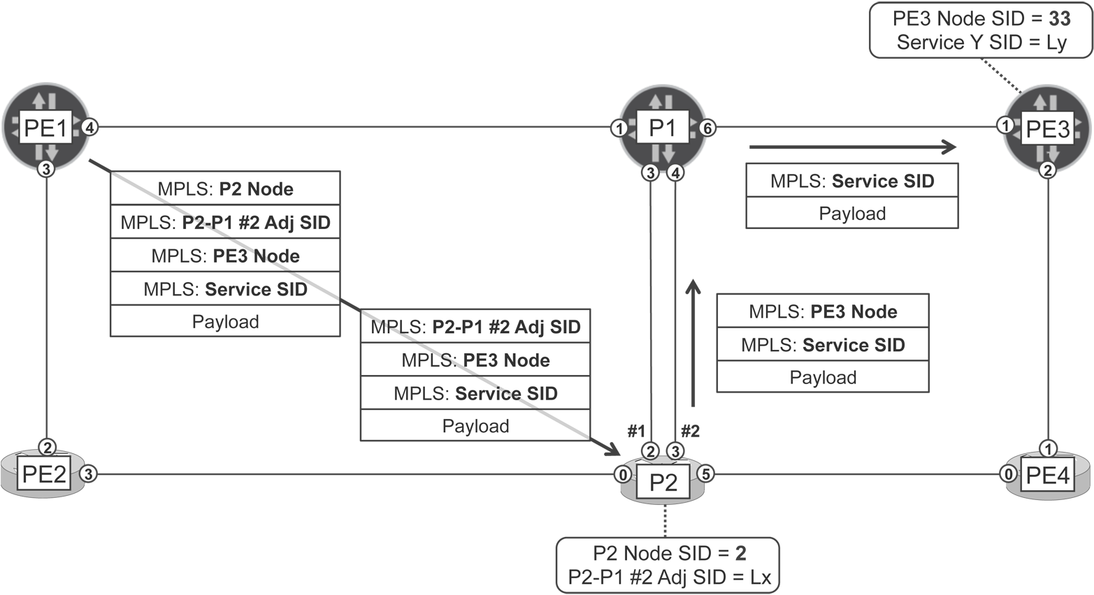
Figure 2-9. Node, adjacency, and service segments
Before sending the packet into the core, PE1 pushes four MPLS headers, each with one label. They are, from top to bottom (remember that all of these labels are locally-significant):
- P2’s Node (Global Segment)
- The outermost label takes the packet from PE1 to P2 in an ECMP-aware manner. PE1 has two equal-cost next hops to reach P2: P1 and PE2. Depending on whether PE1 decides to go via P1 or PE2, the label would be 800002 or 16002, respectively. This is due to the different SRGB Base at P1 and PE2. Then, P1 or PE2 pops the outer header from the packet on its way to P2.
- P2-P1 #2 Adjacency (Local Segment)
- P2 receives the packet with a three-label stack. The outer label,
Lx, represents a local segment, and it identifies an IGP adjacency. This is a new type of segment and it means: pop the label and send the packet over the P2-P1 link #2. This time it is an internal core link, but it could have been an external peering link or even a RSVP-TE LSP beginning at P2. - PE3’s Node (Global Segment)
- P1 receives the packet with a two-label stack. The outer label is 800033, and it is P1’s SRGB Base plus PE3’s Node SID. P1 pops this label before sending the packet to PE3.
- Service Y (Local Segment)
- PE3 receives the packet with just one MPLS header. The label
Lyis a local segment that identifies a service. This new type of segment means: pop the label and map the packet to Service Y.
You can view segments as instructions. When PE1 pushes four headers, it is giving four consecutive instructions to the LSRs in the path: first take the packet to P2, then send it over link P2-P1 #2, then take it to PE3, and then when it arrives at PE3, map it to Service Y. A global instruction can actually require multiple hops to be completed (Node Segments are a good example of this).
PE1 codes a sequence of routing instructions directly in the data packet. This time the instructions are coded as MPLS labels, but SPRING also supports IPv6 (with extension headers) forwarding plane. The key concept here is that the source (PE1) not only decides the next hop, but also the subsequent forwarding decisions. This model is traditionally called Source Routing and this is how the SPRING acronym becomes meaningful.
Back to RSVP-TE, the ingress PE also decided the path. Is that Source Routing, too? Let’s see:
-
You can see back in Figure 2-5 that the RSVP-TE Path messages are actually source-routed. Thanks to the ERO, the ingress PE can decide the exact path of the LSP. Conversely, the data packets typically have one MPLS label only, which is mapped to the LSP. In SPRING terminology, an RSVP-TE LSP is just one segment. So, in the RSVP-TE world, the control plane relies on Source Routing but the forwarding plane does not.
-
SPRING is a totally different paradigm: the control plane is not even routed (IGP packets are flooded hop-by-hop), and the forwarding plane may be source-routed.
Let’s examine each segment type in more detail.
Node Segments are actually a particular subcase (N-flag=1) of Prefix Segments. They are routed along the IGP’s ECMP shortest path and may be rerouted if the IGP topology changes. In that sense, Node Segments are loose next hops. Their Segment IDs must be unique because they have global significance. After they’re shifted by the SRGB Base, the resulting, locally significant, labels are present in the LFIBs of all the LSRs: this is what a global segment stands for.
Adjacency Segments are local segments, which are only installed in the LFIB of the LSR advertising them. Said differently, two LSRs can advertise the same label value for totally different adjacencies. Adjacency Segments can be interpreted as strict next hops. For example, by pushing five MPLS headers, the ingress PE can send a packet into an LSP consisting of five strict next hops.
Service Segments are mapped to a service. What is a service? The following chapters cover several L2 and L3 services in detail. For the time being, it is worth noting that stacking a service label below a transport label (and, more generally, stacking any kind of labels) is a standard MPLS technique, not a new contribution from SPRING.
SPRING Adjacency Segments
Both Junos and IOS XR advertise an Adjacency SID by default for each of its IGP adjacencies.
Following is how the Adjacency SIDs look in Junos and IOS XR CLI.
Example 2-67. SPRING Adjacency SIDs in Junos and IOS XR CLI
juniper@PE1> show isis database PE1.00 extensive
[...]
    IS extended neighbor: PE2.00, Metric: default 10
      IP address: 10.0.0.0
      Neighbor's IP address: 10.0.0.1
      P2P IPV4 Adj-SID - Flags:0x30, Weight:0, Label: 299904
    IS extended neighbor: P1.00, Metric: default 10
      IP address: 10.0.0.2
      Neighbor's IP address: 10.0.0.3
      P2P IPV4 Adj-SID - Flags:0x30, Weight:0, Label: 299920

RP/0/0/CPU0:P2#show isis database verbose PE1.00
[...]
  Metric: 10         IS-Extended PE2.00
    Interface IP Address: 10.0.0.0
    Neighbor IP Address: 10.0.0.1
    ADJ-SID: F:0 B:0 V:1 L:1 S:0 weight:0 Adjacency-sid:299904
  Metric: 10         IS-Extended P1.00
    Interface IP Address: 10.0.0.2
    Neighbor IP Address: 10.0.0.3
    ADJ-SID: F:0 B:0 V:1 L:1 S:0 weight:0 Adjacency-sid:299920
Following is the local meaning of label 299904 at PE1:
-
If PE1 receives a packet with outer MPLS label 299904, it pops the label and sends the packet to PE2 over the link whose remote IPv4 address is 10.0.0.1.
It is worthwhile to have a look at PE1’s Label Forwarding Information Base (LFIB) and look for the Node and Adjacency SIDs in it.
Example 2-68. LFIB at PE1 (Junos)
juniper@PE1> show route table mpls.0
[...]
299904             *[L-ISIS/14] 00:05:27, metric 0
                    > to 10.0.0.1 via ge-2/0/3.0, Pop
299904(S=0)        *[L-ISIS/14] 00:01:10, metric 0
                    > to 10.0.0.1 via ge-2/0/3.0, Pop
299920             *[L-ISIS/14] 00:01:29, metric 0
                    > to 10.0.0.3 via ge-2/0/4.0, Pop
299920(S=0)        *[L-ISIS/14] 00:01:10, metric 0
                    > to 10.0.0.3 via ge-2/0/4.0, Pop
800001             *[L-ISIS/14] 00:01:20, metric 10
                    > to 10.0.0.3 via ge-2/0/4.0, Pop
800001(S=0)        *[L-ISIS/14] 00:01:10, metric 10
                    > to 10.0.0.3 via ge-2/0/4.0, Pop
800002             *[L-ISIS/14] 00:01:20, metric 20
                      to 10.0.0.1 via ge-2/0/3.0, Swap 16002
                    > to 10.0.0.3 via ge-2/0/4.0, Swap 800002
800022             *[L-ISIS/14] 19:49:26, metric 10
                    > to 10.0.0.1 via ge-2/0/3.0, Pop
800022(S=0)        *[L-ISIS/14] 00:01:10, metric 10
                    > to 10.0.0.1 via ge-2/0/3.0, Pop
800033             *[L-ISIS/14] 00:01:20, metric 20
                    > to 10.0.0.3 via ge-2/0/4.0, Swap 800033
800044             *[L-ISIS/14] 00:01:10, metric 30
                      to 10.0.0.1 via ge-2/0/3.0, Swap 16044
                    > to 10.0.0.3 via ge-2/0/4.0, Swap 800044
As you can see, PE1’s LFIB contains all the Node labels (global Node SID + local→remote SRGB Base), and only the local Adjacency SID labels.
Another interesting case is the double P1-P2 link. Depending on the implementation, LSRs may advertise one different Adjacency SID for each link and/or advertise one single Adjacency SID representing both links. As a result, the head-end LER may have the possibility to choose either ECMP or a specific link. The authors did not verify these implementation details in the lab.
A Comparison of LDP, RSVP-TE, and SPRING
So far, this chapter has covered three protocols (or actually four, if you consider SPRING both over IS-IS and OSPF) that are capable of signaling MPLS LSPs. Which one is better? It depends!
MPLS is a flexible technology and depending on the application, the topology, the requirements, and more in some cases, the best fit can be RSVP-TE, or SPRING, or LDP. It really depends on the relative importance of each factor. Table 2-2 summarizes the pros and cons of each of these great technologies.
| Technology | LDP | RSVP-TE | SPRING |
|---|---|---|---|
| Supports Traffic Engineering | No | Yes | With label stacking, no BW reservation. |
| Natively supported by the IGP | No | No | Yes |
| Supports P2MP LSPs | Yes | Yes | Not yet |
| Simple configuration | Yes | With Auto Tunnel | SID provisioning |
| Control plane load | Low | Per-LSP state | Null |
| Deterministic labels | No | No | For global segments |
Deterministic labels have benefits in terms of forwarding plane stability and provide easier troubleshooting. On the other hand, networking devices can simultaneously push a limited number of MPLS labels, which is a factor to consider for SPRING-based TE deployments.
BGP-Labeled Unicast
All of the examples in this chapter rely on BGP to propagate IPv4 unicast routes between different Autonomous Systems (65000, 65001, and 65002). Advertising plain IPv4 prefixes is actually the original application of BGP as described in RFC 4271. This classic BGP flavor is commonly called vanilla BGP, and it is the cornerstone of the IPv4 Internet.
Although the BGP protocol is extremely scalable and flexible, vanilla BGP is only capable of advertising IPv4 unicast prefixes. This is where BGP multiprotocol extensions (RFC 4760) come into play. The word multiprotocol is actually an understatement: with these extensions, BGP can advertise virtually anything. It can be routes, but also MAC addresses, or multicast subscriptions, or security filters, or even label mappings!
In the same way as vanilla BGP exchanges IPv4 routes, multiprotocol BGP exchanges more generic objects called Network Layer Reachability Information (NLRI). Again, there is a wide variety of information that can be encoded in an NLRI, and many times this information has nothing to do with the network layer concept. However, the NLRI acronym remains very popular and it refers to an object (or prefix) announced via multiprotocol BGP.
How can different types of NLRI be identified? Every NLRI has an AFI, SAFI pair. (AFI stands for Address Family Identifier, and SAFI is an acronym for Subsequent Address Family Identifier.) For example, IPv4 unicast is (AFI=1, SAFI=1) and IPv6 unicast is (AFI=2, SAFI=1). You can get the full list of AFI and SAFI here:
-
http://www.iana.org/assignments/address-family-numbers/address-family-numbers.xhtml
-
http://www.iana.org/assignments/safi-namespace/safi-namespace.xhtml
This chapter covers (AFI=1, SAFI=4), an NLRI that contains label mappings, very similar to LDP’s. This flavor of BGP is described in RFC 3107, and its familiar name is Labeled Unicast or simply BGP-LU.
BGP-LU has numerous applications such as interprovider VPN, MPLS in the data center or Seamless MPLS. Chapter 9 and Chapter 16 cover these use cases, many of which are hierarchical. Let’s examine a simple example now.
IGP-Free Large-Scale Data Centers
Fabric Clos topologies have become the de facto underlay architecture in modern data centers. Depending on whether they are MPLS-enabled or not, they are called MPLS fabrics or IP fabrics. Due to its unparalleled scalability, many large-scale data centers use BGP as the only routing protocol inside their fabrics.
Note
Data center underlay terminology (Clos, fabric, stage, leaf, spine, tier) and concepts are fully explained in Chapter 10. For the moment, you can view the fabric as a classic MPLS topology with PEs and Ps.
External BGP (eBGP) is preferred over internal BGP (iBGP) due to its better multipath and loop-detection capabilities.
Note
Most typically, a controller programs the MPLS labels on the server’s FIB. In this case, MPLS-capable servers do not run BGP-LU; only the fabric LSRs do that. Anyway, let’s keep the BGP-everywhere example in this chapter and leave the more realistic scenario for Chapter 16.
Figure 2-10 shows a minimal three-stage fabric topology.
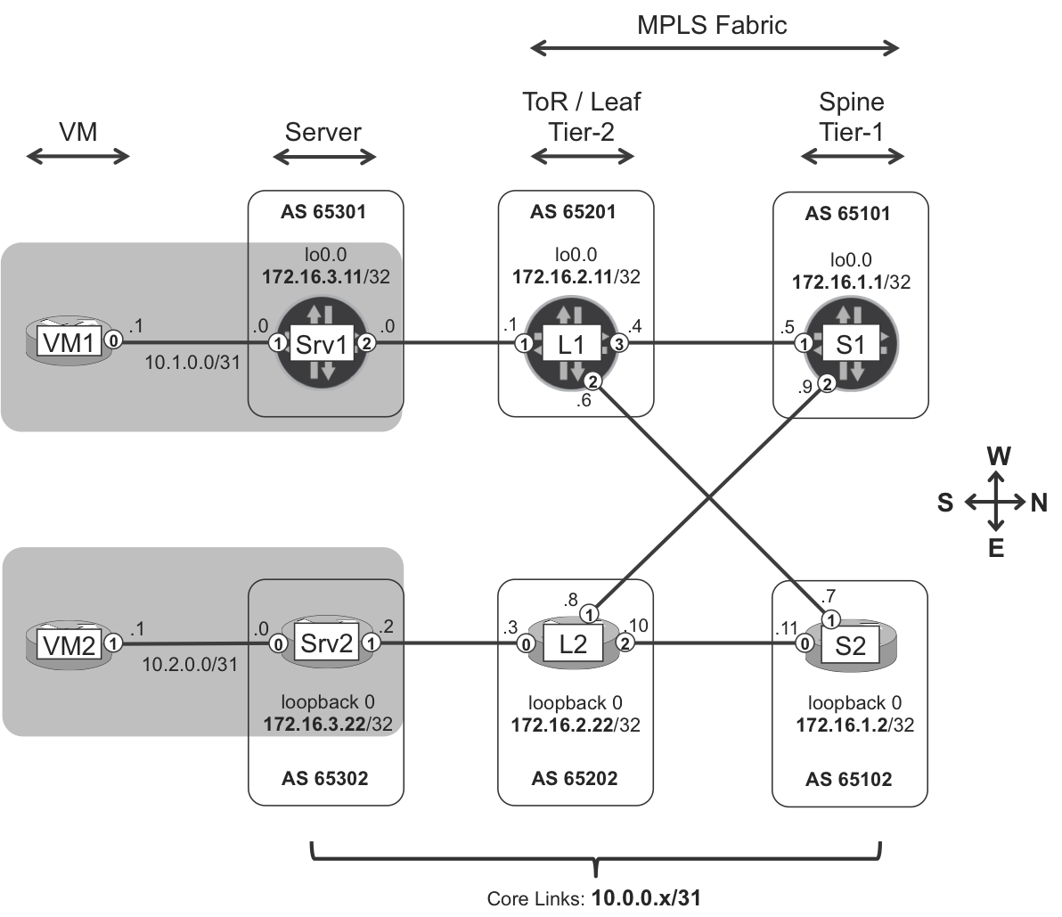
Figure 2-10. IGP-free leaf-and-spine topology
Following are descriptions of the components in Figure 2-10:
-
Virtual machines (VMs) are like CEs: they do not have a MPLS stack.
-
Servers or hypervisors hosting the VMs (or containers) have an MPLS stack. In this example, Junos and IOS XR routers emulate the role of the MPLS-enabled servers. They are lightweight PEs.
-
Top-of-Rack (ToR) or leaf IP/MPLS switches—Tier-2 in this topology—implement Clos fabric stages #1 and #3. They are P-routers.
-
Spine IP/MPLS switches—Tier-1 in this topology—implement Clos fabric stage #2. They are P-routers and, in this example, also service route reflectors.
Note
Large-scale data centers typically have a more complex (5-stage) topology.
Like all the examples in this chapter, Figure 2-10’s scenario provides a global IPv4 unicast service (AFI=1, SAFI=1) with vanilla BGP. Instead of Internet access, this service interconnects VMs in the data center. And for that to be possible, the infrastructure LSPs must be signaled between MPLS-enabled servers; and that is the goal of BGP-LU.
Figure 2-11 illustrates the role of the two types of BGP sessions: vanilla BGP for service, and BGP-LU for transport. All of the MPLS-enabled devices establish single-hop external BGP-LU sessions with all their adjacent neighbors. For example, L1’s eBGP-LU peers are Srv1, S1, and S2. You can view these sessions as a combination of IGP and LDP: they encode infrastructure IPv4 addresses mapped to MPLS labels. Although eBGP-LU does not convey topology information, draft-ietf-rtgwg-bgp-routing-large-dc explains why it remains a great option for large-scale data centers.
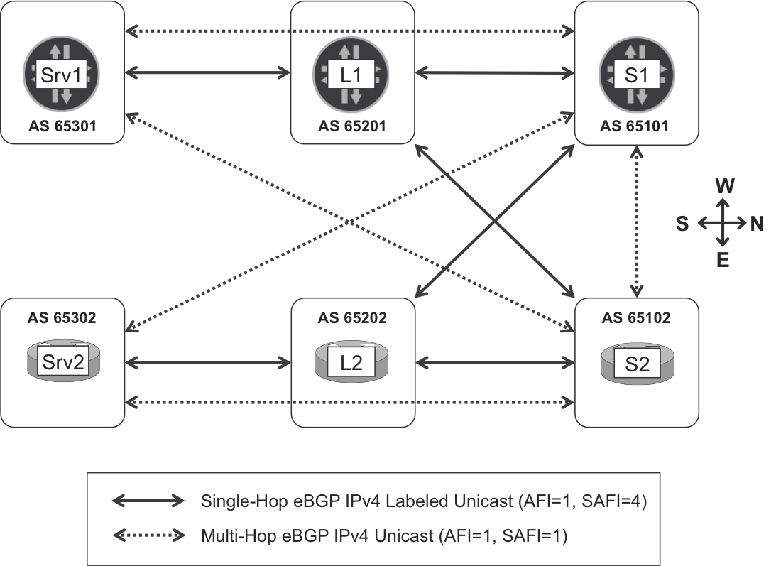
Figure 2-11. BGP sessions in IGP-free leaf-and-spine topology
Tip
Although not shown in this example, it is recommended to use 4-byte AS numbering. Otherwise, the AS:device 1:1 mapping might result in the exhaustion of the AS space.
BGP-LU—policy and community scheme
Let’s clarify the usage of BGP communities in this example before jumping into the configuration details:
- Servers
- Advertise their own loopback addresses 172.16.3.11 and 172.16.3.22, respectively, as eBGP-LU routes with standard community CM-SERVER (65000:3).
- Advertise the VM addresses 10.1.0.0/31 and 10.2.0.0/31, respectively, as vanilla eBGP routes with standard community CM-VM (65000:100).
- Do not readvertise any eBGP route at all.
- Leaf LSRs
- Readvertise all of the eBGP-LU routes. Although they might advertise their local loopback, it is not required for the solution to work.
- Spine LSRs
- Advertise their own loopback addresses 172.16.1.1 and 172.16.1.2, respectively, as eBGP-LU routes with standard community CM-RR (65000:1).
- Readvertise only those vanilla eBGP routes with community CM-VM.
- Readvertise only those eBGP-LU routes with community CM-SERVER.
This careful community scheme is due to the fact that IOS XR keeps labeled and unlabeled IP routes in the same global table, so it is important not to readvertise labeled routes as unlabeled routes, or vice versa. Said differently, you need to pay special attention so that the SAFI=1 and SAFI=4 worlds remain independent.
As you can see, communities CM-VM and CM-SERVER play a key role in the route advertising flow. Conversely, the community CM-RR plays a subtler role that we’ll look at a bit later.
BGP-LU Configuration
In general, IOS XR treats the label as an additional property of the IP unicast route. On the other hand, Junos treats labeled unicast and unlabeled unicast routes as different entities, keeping them in different tables by default.
Junos—copying interface routes from inet.0 to inet.3
The role of the inet.0 and inet.3 routing tables in Junos has already been explained. Nonetheless, here’s a quick refresher:
-
inet.0is the global IPv4 routing table that populates the FIB and is typically populated by IP routing protocols (IGP, vanilla BGP, etc.). -
inet.3is an auxiliary table for BGP next-hop resolution and is typically populated by MPLS signaling protocols (LDP, RSVP, SPRING-enabled IGP, etc.)
But is BGP-LU an IP routing protocol or an MPLS signaling protocol? Actually, it’s both. In Junos, you can configure it in two modes:
-
BGP-LU installs prefixes in
inet.0and picks prefixes frominet.0for further advertising. Optionally, explicit configuration might copy all (or a selection of) the prefixes into theinet.3table, enabling BGP next-hop resolution for MPLS services. -
BGP-LU installs prefixes in
inet.3and picks prefixes frominet.3for further advertising. Optionally, explicit configuration might copy all (or a selection of) the prefixes into theinet.0table, enabling IPv4 forwarding with labeled next hop toward these prefixes.
This book uses the second method because it provides more flexibility. For example, with this model, a single BGP session can exchange prefixes from plain unicast and labeled unicast address families. Also, it is a good choice in terms of scalability because BGP-LU prefixes are not automatically installed in the FIB, relaxing the FIB load on low-end devices. The configuration is slightly more complex, though.
OK, let’s make BGP-LU work on the inet.3 routing table. The first step at Srv1 is to copy the local loopback address from inet.0 (where it resides by default) to inet.3, so BGP-LU can advertise it in later steps.
Example 2-69. Copying an interface route from inet.0 to inet.3 at Srv1 (Junos)
1     policy-options {
2         policy-statement PL-LOCAL-LOOPBACK {
3             term LOCAL-LOOPBACK {
4                 from interface lo0.0;
5                 then {
6                     metric 0;
7                     origin incomplete;
8                     community add CM-SERVER;
9                     accept;
10                }
11            }
12            term DIRECT {
13                from protocol direct;
14                then reject;
15            }
16        }
17        community CM-SERVER members 65000:3;
18    }
19    routing-options {
20        interface-routes {
21            rib-group inet RG-LOCAL-LOOPBACK;
22        }
23        rib-groups {
24            RG-LOCAL-LOOPBACK {
25                import-rib [ inet.0 inet.3 ];
26                import-policy PL-LOCAL-LOOPBACK;
27    }}}
A similar configuration is required on S1, just with a different community: CM-RR. The usage and relevance of all these communities is explained later. The service does not require L1’s loopback to be advertised; hence, this configuration is optional for L1 (you can use another community such as 65000:2 for L1 and L2 loopbacks).
A rib-group is like a template. It contains an ordered list of RIBs (line 25). The list begins with a single primary RIB (inet.0 here) where the to-be-copied prefixes originally reside, and then it lists one or more secondary RIBs (only inet.3 here) to which the prefixes must be copied. The rib-group is then applied to a protocol, or in this case, to the interface routes (lines 20 and 21) because the local loopback is one of them. As a result, the route 172.16.3.11/32 is copied from inet.0 to inet.3.
If no policy were specified, all the interface routes would be now in both inet.0 and inet.3. The policy (PL-LOCAL-LOOPBACK) performs a selective copy of the local loopback route only. Also, to provide consistency between Junos and IOS XR, the policy changes two route attributes:
-
By default, there is no Multi Exit Discriminator (MED) in Junos, and in IOS XR it is set to zero. The policy sets the MED to zero for consistency across vendors.
-
By default, the origin in Junos and IOS XR is
igpandincomplete, respectively. The policy sets it toincomplete.
Tip
It is a good practice to also add a geographical or location community that will eventually help to filter the prefixes based on where the prefix is originally injected.
Note that the policy can only select or modify the routes installed in the secondary RIBs; it has no effect on the primary RIB. Also, if there were several secondary RIBs, the to rib knob makes the action specific to a subset of the secondary RIBs only.
Now that the configuration is applied, let’s have a look at the local loopback route.
Example 2-70. Effect of copying the Local Loopback Route—Srv1 (Junos)
juniper@Srv1> show route 172.16.3.11/32 detail

inet.0: 11 destinations, 12 routes (11 active, 0 holddown, 0 hidden)
172.16.3.11/32 (1 entry, 0 announced)
(...)
                Secondary Tables: inet.3

inet.3: 12 destinations, 12 routes (12 active, 0 holddown, 0 hidden)
172.16.3.11/32 (1 entry, 1 announced)
(...)
                Communities: 65000:3
                Primary Routing Table inet.0
The loopback IPv4 address is copied to inet.3 (secondary table), and the copied route has a new community. A similar check on other local link address (e.g., 10.0.10.8/31) only shows the route in inet.0, due to the policy constraints at the rib-group.
Junos—BGP-LU configuration
The next step is to assign a label to the route and advertise it with BGP-LU.
Example 2-71. eBGP-LU configuration—Srv1 (Junos)
protocols {
    bgp {
        group eBGP-LU-65201 {
            family inet {
                labeled-unicast {
                    per-prefix-label;
                    rib {
                        inet.3;
                    }
                }
            }
            export PL-LOCAL-LOOPBACK;
            peer-as 65201;
            neighbor 10.0.0.1;
}}}
Note
BGP-LU’s per-prefix-label knob is equivalent to LDP’s deaggregate. It is recommended in BGP-LU to improve convergence times. However, because it raises the scalability requirements on the peers, it is not recommended for other BGP address families. Chapter 3 discusses this topic more in detail.
A similar configuration is required on S1. As for L1, it does not need any export policies, because Junos readvertises eBGP prefixes by default.
With the previous configuration (Example 2-71), Srv1 advertises its labeled loopback to L1, as you can see in the following example.
Example 2-72. Local loopack advertisement via BGP-LU—Srv1 (Junos)
juniper@Srv1> show route advertising-protocol bgp 10.0.0.1
             172.16.3.11 detail

inet.3: 12 destinations, 12 routes (12 active, 0 holddown, ...)
* 172.16.3.11/32 (1 entry, 1 announced)
 BGP group eBGP-LU-65201 type External
     Route Label: 3
     Nexthop: Self
     Flags: Nexthop Change
     AS path: [65301] I
     Communities: 65000:3
     Entropy label capable
As expected, Srv1 assigns the implicit null label to enable PHP.
IOS XR—BGP-LU configuration
Following is the IOS XR configuration at Srv2.
Example 2-73. eBGP-LU configuration—Srv2 (IOS XR)
1     route-policy PL-LOCAL-INTERFACES
2       if destination in (172.16.3.22/32) then
3         set community CM-SERVER
4         pass
5       endif
6     end-policy
7     !
8     route-policy PL-LOCAL-LOOPBACK
9       if community matches-any CM-SERVER then
10        pass
11      else
12        drop
13      endif
14    end-policy
15    !
16    route-policy PL-ALL
17      pass
18    end-policy
19    !
20    community-set CM-SERVER
21      65000:3
22    end-set
23    !
24    router bgp 65302
25     mpls activate
26      interface GigabitEthernet0/0/0/1
27     !
28     address-family ipv4 unicast
29      redistribute connected route-policy PL-LOCAL-INTERFACES
30      allocate-label all
31     !
32     neighbor 10.0.0.3
33      remote-as 65202
34      address-family ipv4 labeled-unicast
35       send-community-ebgp
36       route-policy PL-LOCAL-LOOPBACK out
37       route-policy PL-ALL in
38    !
39    router static
40     address-family ipv4 unicast
41      10.0.0.3/32 GigabitEthernet0/0/0/1
The local loopback is labeled and announced via eBGP-LU with the following actions:
-
Redistribute the local loopback (lines 1 through 6, and 29) into BGP. The
PL-LOCAL-INTERFACESpolicy is later extended during vanilla BGP configuration. -
Allocate labels to the unicast routes (line 30). It is recommended to apply a policy here in order to select the routes that require label allocation.
-
Attach (line 36) a BGP outbound policy (lines 8 through 14) to only advertise the local loopback with the appropriate community. In this case, this community is set during route redistribution but it could have been set during route announcement, too.
A similar configuration is required on L2 and S2, just with different policies, as detailed in “BGP-LU—policy and community scheme”.
Sending communities over eBGP is turned on by default on Junos; you need to turn it on explicitly for IOS XR (line 35).
Note
Beware of the else drop action in line 12. This is fine for servers, which only need to advertise their own loopback. Leaf-and-spine LSRs, however, need to allow the readvertisement of eBGP-LU routes, too. Their policies need to be less restrictive.
Furthermore, in IOS XR there is a default “reject all” inbound and outbound route policy applied to eBGP sessions. Explicit policies are required to accept and advertise eBGP routes (lines 16 through 18, 36 and 37).
When the previous configuration (Example 2-73) is applied, Srv2 advertises its loopback via eBGP-LU, as demonstrated in Example 2-74.
Example 2-74. Local loopack advertisement via BGP-LU—Srv2 (IOS XR)
RP/0/0/CPU0:Srv2#show bgp ipv4 labeled-unicast advertised

172.16.3.22/32 is advertised to 10.0.0.3
[...]
  Attributes after outbound policy was applied:
    next hop: 10.0.0.2
    MET ORG AS COMM
    origin: incomplete  metric: 0
    aspath: 65302
    community: 65000:3
Warning
Incomplete configurations may cause the learned eBGP-LU routes to remain unresolved. You can check that by using the IOS XR command show cef unresolved. A similar and very useful Junos command is show route hidden.
This is why a static route toward L1’s peer interface is configured (Example 2-73, lines 39 through 41). Thanks to that, Srv2 can resolve the eBGP-LU routes. Let’s see it.
Example 2-75. Inter-server labeled reachability—Srv2 (IOS XR)
RP/0/0/CPU0:Srv2#show cef 172.16.3.11
172.16.3.11/32, version 159, internal 0x1000001 [...]
 Prefix Len 32, traffic index 0, precedence n/a, priority 4
   via 10.0.0.3, 6 dependencies, recursive, bgp-ext [flags 0x6020]
    path-idx 0 NHID 0x0 [0xa1558774 0x0]
    recursion-via-/32
    next hop 10.0.0.3 via 24006/0/21
     local label 24004
     next hop 10.0.0.3/32 Gi0/0/0/1 labels imposed {ImplNull 24005}
Service Configuration in an IGP-Less Topology
Now that the LSP signaling infrastructure is in place, it is time to signal the service routes corresponding to the VMs. For that to happen, Srv1 and Srv2 need to establish vanilla multihop eBGP sessions with the service route reflectors S1 and S2.
Nothing special is required in IOS XR, but Junos needs to get the remote loopbacks—previously learned via single-hop eBGP-LU—copied from inet.3 to inet.0 so that multihop vanilla eBGP sessions can be established.
Junos—copying eBGP-LU routes from inet.3 to inet.0
Back in Example 2-69 and Example 2-70, the local loopback route was copied from inet.0 to inet.3—this was so it could be advertised via eBGP-LU. Now, the process is the reverse: certain routes learned via eBGP-LU need to be copied from inet.3 to inet.0—so that they are reachable from a pure IPv4 forwarding perspective. The following example illustrates how to achieve it.
Example 2-76. Copying eBGP-LU routes from inet.3 to inet.0—Srv1 (Junos)
policy-options {
    policy-statement PL-RR-INET {
        term RR {
            from community CM-RR;
            then accept;
        }
        then reject;
    }
    community CM-RR members 65000:1;
}
routing-options {
    rib-groups {
        RG-RR-INET {
            import-rib [ inet.3 inet.0 ];
            import-policy PL-RR-INET;
        }
    }
}
protocols {
    bgp {
        group eBGP-LU-65201 {
            family inet {
                labeled-unicast {
                    rib-group RG-RR-INET;
}}}}}
As mentioned earlier, S1 and S2 are advertising their local loopback routes with community CM-RR. As a result of the copy in Example 2-76, these routes are installed in both inet.3 and inet.0 at Srv1, as shown in Example 2-77.
Example 2-77. Effect of copying an eBGP-LU route—Srv1 (Junos)
juniper@Srv1> show route 172.16.1.1/32 detail

inet.0: 11 destinations, 12 routes (11 active, 0 holddown, 0 hidden)
172.16.1.1/32 (1 entry, 0 announced)
(...)
                Communities: 65000:1
                Primary Routing Table inet.3

inet.3: 12 destinations, 12 routes (12 active, 0 holddown, 0 hidden)
172.16.3.11/32 (1 entry, 1 announced)
(...)
                Communities: 65000:1
                Secondary Tables: inet.0
Likewise, S1 is configured to copy all the routes with community CM-SERVER from inet.3 to inet.0. Here is a summary of the use of communities so far:
-
Srv1 and Srv2 announce their loopbacks with community CM-SERVER.
-
S1 and S2 announce their loopbacks with community CM-RR.
-
Srv1 copies eBGP-LU routes with community CM-RR from
inet.3toinet.0. -
S1 copies eBGP-LU routes with community CM-SERVER from
inet.3toinet.0. -
Srv2 and S2 run IOS XR, which does not have a resolution RIB, so no route copy is needed.
At this point, IPv4 connectivity between PEs (Srv1, Srv2) and RRs (S1, S2) is guaranteed and multihop vanilla eBGP sessions can be established as in Figure 2-11’s dotted lines.
Junos—Vanilla eBGP configuration in IGP-less topology
Following is the service configuration at Srv1.
Example 2-78. Vanilla BGP configuration in IGP-less topology—Srv1 (Junos)
policy-options {
    policy-statement PL-eBGP-INET-OUT {
        term VM-INTERFACE {
            from interface ge-2/0/1.0;
            then {
                community add CM-VM;
                accept;
            }
        }
        then reject;
    }
    community CM-VM members 65000:100;
}
protocols {
    bgp {
        group eBGP-INET {
            multihop;
            local-address 172.16.3.11;
            export PL-eBGP-INET-OUT;
            neighbor 172.16.1.1 { peer-as 65101; }
            neighbor 172.16.1.2 { peer-as 65102; }
}}}
And Example 2-79 shows the service configuration at S1.
Example 2-79. Vanilla BGP configuration in IGP-less topology—S1 (Junos)
1     policy-options {
2         policy-statement PL-eBGP-INET-OUT {
3             term VM {
4                 from community CM-VM;
5                 then accept;
6             }
7             then reject;
8         }
9     }
10    protocols {
11        bgp {
12            group eBGP-INET {
13                multihop {
14                    no-nexthop-change;
15                }
16                local-address 172.16.1.1;
17                export PL-eBGP-INET-OUT;
18                neighbor 172.16.3.11 { peer-as 65301; }
19                neighbor 172.16.3.22 { peer-as 65302; }
20    }}}
Here is the logic behind this configuration: MPLS-enabled servers advertise the VM prefixes with community CM-VM. Service RRs—S1 and S2, which in this example happen to be spine LSRs, too—only reflect routes with the community CM-VM. This prevents any unexpected leaking between labeled and unlabeled routes. A very important piece of configuration is in line 14. By default, announcing a prefix to a different AS triggers a BGP next-hop attribute rewrite. This is not desired for service route reflection, and this is why no-nexthop-change is configured.
IOS XR—vanilla eBGP configuration in IGP-less topology
Following is the service configuration at Srv2.
Example 2-80. Vanilla BGP configuration in IGP-less topology—Srv2 (IOS XR)
route-policy PL-LOCAL-INTERFACES
  if destination in (172.16.3.22/32) then
    set community CM-SERVER
    pass
  endif
  if destination in (10.2.0.0/31) then
    set community CM-VM
    pass
  endif
end-policy
!
route-policy PL-eBGP-INET
  if community matches-any CM-VM then
    pass
  else
    drop
  endif
end-policy
!
community-set CM-VM
  65000:100
end-set
!
router bgp 65302
 neighbor-group eBGP-INET
  ebgp-multihop 255
  update-source Loopback0
  address-family ipv4 unicast
   send-community-ebgp
   redistribute connected route-policy PL-LOCAL-INTERFACES
   route-policy PL-eBGP-INET out
   route-policy PL-eBGP-INET in
 !
 neighbor 172.16.1.1
  remote-as 65101
  use neighbor-group eBGP-INET
 !
 neighbor 172.16.1.2
  remote-as 65102
  use neighbor-group eBGP-INET
The logic is similar to Junos. Only the VM routes, flagged with community CM-VM, are advertised as unlabeled IPv4 prefixes toward the service RRs.
Remember that the PL-LOCAL-INTERFACES policy is in control of the redistribution of interface routes into BGP (Example 2-73, line 29). The local loopback and the VM route are flagged with community CM-SERVER and CM-VM, respectively. With this entire configuration in place, the local loopback is only distributed via eBGP-LU, whereas the VM route is only distributed via vanilla BGP.
The configuration at S2 is similar, with two differences. First, it reflects only remote VM routes, so it does not have any local VM route to announce. Second, it must not change the BGP next-hop attribute, so the extra configuration is required.
Example 2-81. Vanilla BGP configuration in IGP-less topology—S2 (IOS XR)
router bgp 65302
 neighbor-group eBGP-INET
  address-family ipv4 unicast
   next-hop-unchanged
BGP-LU—Signaling and Forwarding Plane
Figure 2-12 puts it all together by showing the end-to-end signaling and forwarding in detail.
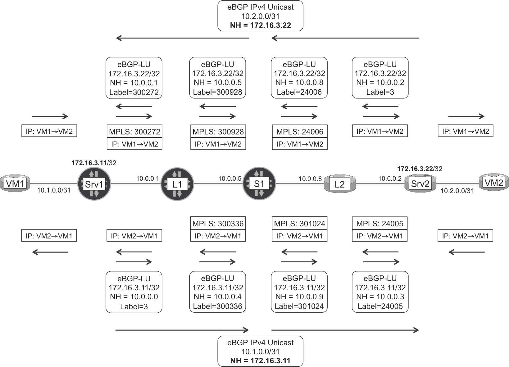
Figure 2-12. Signaling and forwarding in an IGP-free topology
Although only one path is shown, you can definitely configure multipath in eBGP-LU so that traffic can also transit S2.
Let’s have a look at the traceroute between VM1 and VM2.
Example 2-82. Traceroute from VM1 to VM2
RP/0/0/CPU0:VM#traceroute vrf VM1 10.2.0.1
[...]

 1  10.1.0.0 0 msec  0 msec  0 msec
 2  10.0.0.1 [MPLS: Label 300272 Exp 0] 0 msec  0 msec  9 msec
 3  10.0.0.5 [MPLS: Label 300928 Exp 0] 0 msec  0 msec  0 msec
 4  10.0.0.8 [MPLS: Label 24006 Exp 0] 0 msec  0 msec  0 msec
 5  10.0.0.2 0 msec  0 msec  0 msec
 6  10.2.0.1 0 msec  *  39 msec
Let’s see how the LSPs are signaled. Each PE has three BGP sessions in total: one BGP-LU session (single-hop to the adjacent P) and two vanilla BGP sessions to the RRs.
The routing and forwarding state at the Junos ingress PE is shown in Example 2-83.
Example 2-83. Signaling and MPLS forwarding at ingress PE—Srv1 (Junos)
juniper@Srv1> show route 10.2.0.1
              receive-protocol bgp 172.16.1.1 detail

inet.0: 11 destinations, 12 routes (11 active, 0 holddown, [...])
* 10.2.0.0/31 (2 entries, 1 announced)
     Accepted
     Nexthop: 172.16.3.22
     AS path: 65101 65302 ?
     Communities: 65000:100

juniper@Srv1> show route 172.16.3.22 table inet.3
              receive-protocol bgp 10.0.0.1 detail

inet.3: 12 destinations, 12 routes (12 active, 0 holddown, [...])
* 172.16.3.22/32 (1 entry, 1 announced)
     Accepted
     Route Label: 300272
     Nexthop: 10.0.0.1
     AS path: 65201 65101 65202 65302 ?
     Communities: 65000:3

juniper@Srv1> show route 172.16.3.22 table inet.3

inet.3: 12 destinations, 12 routes (12 active, 0 holddown, 0 hidden)
+ = Active Route, - = Last Active, * = Both

172.16.3.22/32     *[BGP/170] 06:18:31, localpref 100
                      AS path: 65201 65101 65202 65302 ? [...]
                    > to 10.0.0.1 via ge-2/0/2.0, Push 300272

juniper@Srv1> show route forwarding-table destination 10.2.0.1
Routing table: default.inet
Internet:
Destination      Type Next hop  Type       Index  Nhref Netif
10.2.0.1/31      user           indr     1048576  2
                      10.0.0.1  Push 300272  588  2     ge-2/0/2.0
Srv1 pushes an MPLS header and sends the packet to the forwarding next hop, L1, with label 300272. This is the label that L1 advertises for 172.16.3.22 via eBGP-LU. L1 swaps the label for 300928, sends the packet to S1, and so on.
Finally, if you look at the reverse flow (VM2→VM1) shown in Figure 2-12 and Example 2-84, Srv2 acts as an ingress PE.
Example 2-84. Vanilla BGP routing state at ingress PE—Srv2 (IOS XR)
RP/0/0/CPU0:Srv2#show route 10.1.0.1

Routing entry for 10.1.0.0/31
  Known via "bgp 65302", distance 20, metric 0
  Tag 65101, type external
  Routing Descriptor Blocks
    172.16.3.11, from 172.16.1.1, BGP external
      Route metric is 0
  No advertising protos.
You can combine Example 2-75 (Srv2# show cef 172.16.3.11/32, next hop 10.0.0.3, labels imposed {ImplNull 24005}) with Example 2-84 and obtain the packet sent by Srv2 to L2 in Figure 2-12.
Forwarding at the transit Ps has been skipped here for the sake of brevity. It follows the same principles as the other protocols. Simply, the protocol changes; for example, there are BGP routes in mpls.0.
BGP-LU—SPRING Extensions
Deterministic labels require manual provisioning and have several advantages:
-
They improve resiliency by reducing the likelihood of events that require reprogramming the label stacks on the FIB. This is especially important in large-scale data centers whose devices might need to store a high amount of label forwarding state.
-
They ease the integration with external controllers that are able to program a label stack on MPLS-capable servers. This becomes relevant if the servers do not speak BGP-LU or other MPLS protocols with the fabric. In addition, by programming stacks of labels, this architecture enables explicit routing à la SPRING.
-
They provide easier operation and troubleshooting.
As described in draft-ietf-idr-bgp-prefix-sid, it is possible to use the SPRING paradigm with BGP thanks to the BGP-Prefix-SID Label Index attribute.
Let’s see how it works with the help of Figure 2-13
.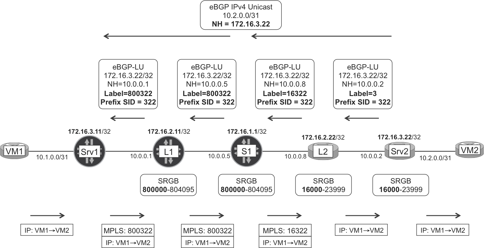
Figure 2-13. BGP-LU with SPRING extensions
Here is the sequence on the control plane:
-
Srv2 has a policy that assigns the Prefix SID value 322 to the prefix 172.16.3.22/32. This time it is Srv2’s local loopback but it could be any other prefix—used as BGP next hop—referenced by the policy; hence, the name Prefix SID and not Node SID. This value must be unique in the domain and assigned by a central administration entity, as it is also the case for IGP-based SPRING.
-
Srv2 sends the eBGP-LU route 172.16.3.22/32 with an implicit null label and the locally configured Prefix SID.
-
L2 receives the route and allocates a label for the prefix 172.16.3.22/32. This new label is locally significant to L2 but its value is not arbitrary: L2 calculates it by adding its local SRGB to the received Prefix SID: 16000 + 322 = 16322. After it allocates the label, L2 advertises it with a regular eBGP-LU update, but this time it adds also the Prefix SID, allowing S1 to repeat the logic.
The same process is repeated on S1 and L1, which have a different SRGB from L2.
Here are a couple of interesting differences between IGP-based SPRING and BGP-based SPRING:
-
IGP-based SPRING does not advertise labels.
-
BGP-based SPRING does advertise labels because it is based on BGP-LU. In addition, the BGP updates also contain the SID and the SRGB (the latter is not shown in Figure 2-13).
As of this writing, this feature is under development for Junos and IOS XR. The authors had access to a Junos prototype and this is how the eBGP-LU export policy can be modified in order for Srv1 to assign and announce a prefix SID for its local loopback.
Example 2-85. Assigning a prefix SID—Srv1 (Junos)
policy-options {
    policy-statement PL-LOCAL-LOOPBACK {
        term LOCAL-LOOPBACK {
            then {
                prefix-segment-index 311;
}}}}
SPRING Anycast
Anycast segments allow sharing the same SID (for a given so-called anycast prefix) among a group of devices. Several drafts cover two possible scenarios: if all of the anycast nodes advertising a given SID use the same SRGB, or if they use different SRGBs. Further details are beyond the scope of this book.
Note
A related technology called Egress Peer Engineering (EPE) is discussed in Chapter 13.