
Chapter 20. FIB Optimization for Fast Restoration
In Chapter 18 and Chapter 19, you discovered different ways to protect the traffic in case of transit node or transit link failure. All the methods are based on preinstalling a backup next hop in the hardware Forwarding Information Base (HW FIB). Upon network failure, the primary next hop is removed from the HW FIB and traffic uses the preinstalled backup next hop. The difference between each method lies in how the backup next hop is determined and how the backup path is established.
This chapter explores additional FIB optimization techniques that you can implement on the ingress PE to improve failover convergence. PE nodes typically hold a large number of service prefixes. A prefix in this context can be a typical L3 VPN prefix, but it can also be information required to forward traffic using other types of services, such as pseudowires (PWs) signaled by using BGP or LDP. When it comes to optimization of failover times on the ingress PE, there are two main areas requiring special attention:
-
Optimization of next-hop structures in the hardware FIB
-
Preinstallation of the next hop associated with the backup egress PE
These optimization techniques are explored in the next two sections.
Next-Hop Hierarchy
If you go back and reexamine Figure 18-1 carefully, you probably realize that failure case number 3 is not exactly the same as failure case numbers 5 or 7. Similarly, failure case number 4 is not quite the same as failure case number 6. What makes failure cases 3 or 4 different from failure cases 5, 6, or 7? The scale!
In failure cases 5, 6, and 7, the Point of Local Repair (PLR) is a pure-P router. The pure-P router typically has a very limited number of prefixes. Only infrastructure prefixes (loopback and link addresses of MPLS transport infrastructure network) are present on the P router. Even in very large MPLS transport networks, with several thousands of nodes, the number of infrastructure prefixes does not exceed 10,000 to 20,000. On PE routers, however, the number of service prefixes can reach several hundred thousand, if not a million routes in very highly scaled designs.
Why is this scaling difference important from a failover perspective? The local repair techniques discussed in previous chapters are based on the following:
-
Preinstalling both primary and backup next hops in the HW FIB
-
Removing primary next hops from the HW FIB after detecting failure
It’s easy to imagine that removing the primary next hops associated with 10,000 routes is much faster than removing the primary next hops associated with one million routes, unless some tricks are in place to ensure that the primary next-hop removal does not depend on the number of prefixes.
And this trick is actually the hierarchical—that is, not flat—structure of next hops installed in the HW FIB. In Junos, such hierarchical next-hop structures are called indirect next hops or chained composite next hops, whereas in IOS XR, you can find the term Prefix Independent Convergence (PIC) Core to describe this. Whatever term is used, it is about next-hop hierarchy.
Topology used in Chapter 20 and in Chapter 21
As of this writing, some of the features discussed in Chapter 20 and Chapter 21 are not implemented on the virtualized x86-based network operating system flavors. For this reason, we used a physical topology, and because we only had one physical ASR 9000, the topology looked like in Figure 20-1. Fortunately, it was enough to test all the features.
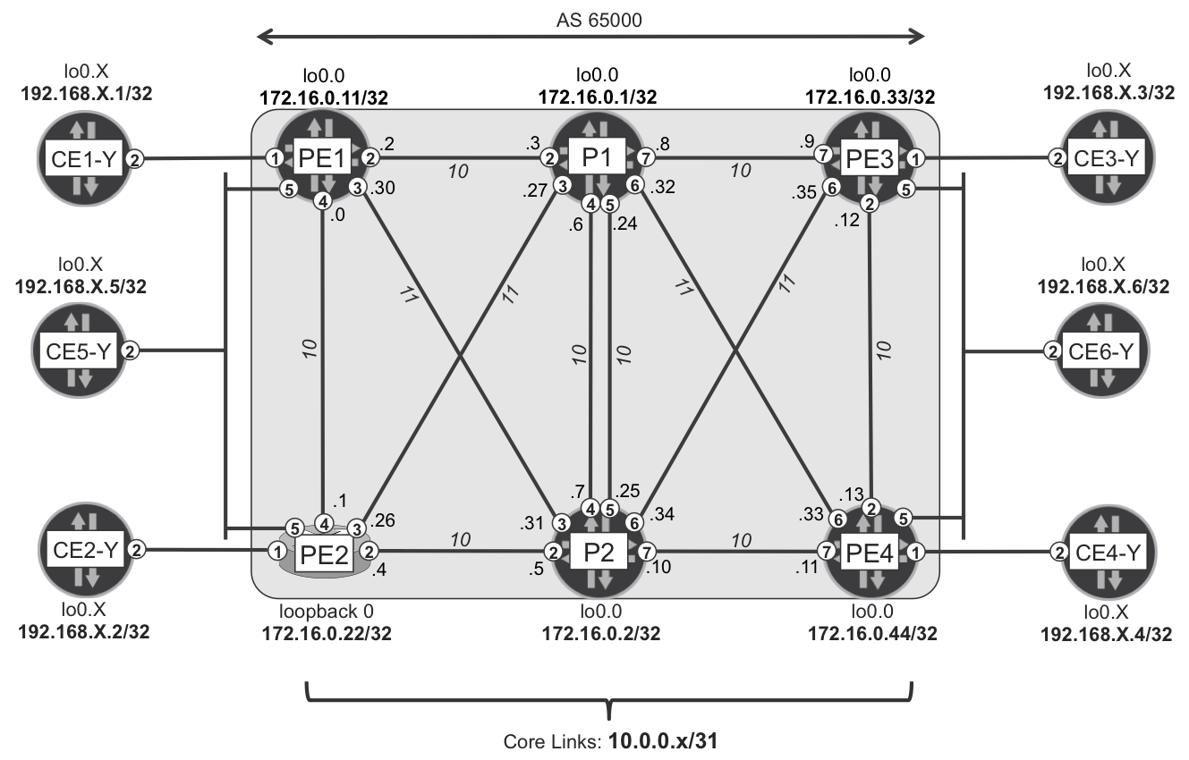
Figure 20-1. Chapter 20 and Chapter 21 topology
In the topology shown in Figure 20-1, various MPLS services are implemented. These are listed in Table 20-1. Configuration of these services is standard, as is discussed in Chapter 3 and Chapter 6, and so the configurations are not covered in this chapter. Additionally, in this topology, LDP with basic LFA (without R-LFA) provides the MPLS transport with local repair style protection.
| Service | Customer edge (CE) nodes |
|---|---|
| L3VPN-B | CE1-B, CE2-B, CE3-B, CE4-B, CE5-B, CE6-B |
| L3VPN-C | CE1-C, CE2-C, CE3-C, CE4-C, CE5-C, CE6-C |
| LDP PW 413 | CE1-D, CE3-D |
| LDP PW 424 | CE2-D, CE4-D |
| LDP PW 456 | CE5-D (dual-homed), CE6-D (dual-homed) |
| LDP PW 513 | CE1-E, CE3-E |
| LDP PW 524 | CE2-E, CE4-E |
| LDP PW 556 | CE5-E (dual-homed), CE6-E (dual-homed) |
| BGP L2VPN-F | CE1-F (single-homed), CE6-F (dual-homed) |
| BGP L2VPN-G | CE2-G (single-homed), CE6-G (dual-homed) |
Flat Next-Hop Structures
Before discussing hierarchal next-hop structures, let’s first have a look at a simple, flat FIB next-hop structure without any hierarchy, as depicted in Figure 20-2. Such flat FIB structures were typically used in the past on some of the older router hardware platforms.
Figure 20-2 shows some entries in the FIB from the perspective of the PE3 router, all of them pointing to PE1. You can see three VPN prefixes (loopback of CE1-B, loopback of VRF-B on PE1, and PE1→CE1-B link prefix). Furthermore, you can see FIB entries corresponding to the LDP-based pseudowire 413 and pseudowire 513 established between PE3 and PE1. The last FIB entry corresponds to the BGP-based L2VPN-F built between PE1 (attached to single-homed CE1-F) and PE3/PE4 (attached to dual-homed CE6-F). More FIB entries can exist, of course; these are just some examples.
Now, thanks to LDP with LFA protection, each FIB entry has two next-hops: the primary next-hop (with weight 0x0001) and backup next hop (with weight 0xF000). The primary path to reach PE1 from PE3 is via P1 (via interface ge-2/0/7; path cost: 20), and the loop-free backup path via P2 (via interface ge-2/0/6; path cost: 22). So far, the FIB structure still reflects what was previously discussed in Chapter 18 and Chapter 19.
If the PE3→P1 link (or P1 node) fails, the primary next hop (associated with ge-2/0/7 interface) is removed from the FIB, and traffic continues to flow using the preinstalled backup next hop (associated with ge-2/0/6 interface). How long does it take to remove the primary next hop from the HW FIB? For these six example prefixes, you need to remove six next hops, so it is rather quick. However, you can easily imagine that PE1 doesn’t advertise only six service prefixes (L3VPN, L2VPN, etc.) to PE3; it might have hundreds of thousands of service prefixes, which is frequently the case in large-scale designs. Now, how long does it take to remove a few hundred thousand next hops from HW FIB? Certainly much longer. Thus, despite the quick failure discovery and the preinstallation of backup next hops in FIB, the recovery time can be very long.
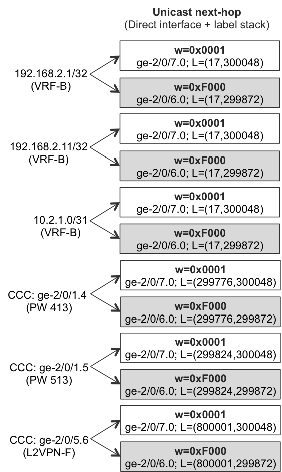
Figure 20-2. Legacy flat FIB next-hop structure on PE3 (Junos)
Indirect Next Hop (Junos)
Here is where designs with hierarchical next-hop structures in the FIB come into play. Similar to the example of the flat FIB in Figure 20-2, you can see an example of hierarchical FIB structure on PE3 in Figure 20-3.
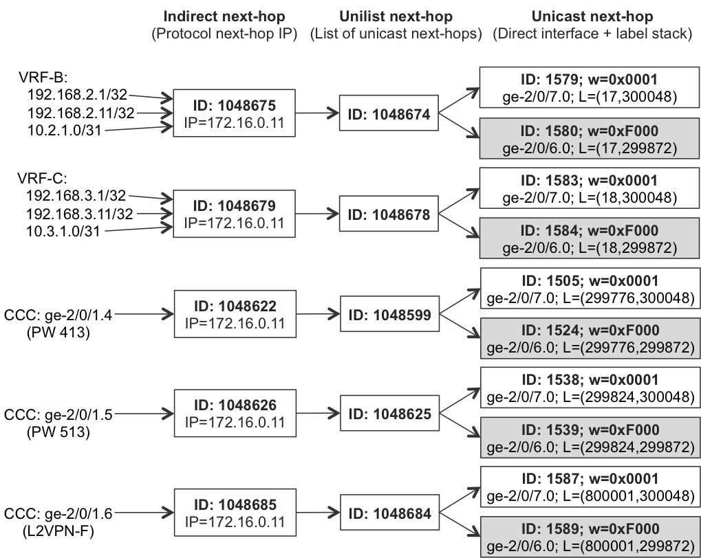
Figure 20-3. Hierarchical (indirect next hop) FIB structure on PE3 (Junos)
Note
Flat FIB structures are no longer used or recommended. With modern routers, the hierarchical FIB is enabled by default, and in many cases it is not even possible to revert the FIB to a flat next-hop structure.
Depending on the actual hardware, the indirect next hop might not be enabled by default. In that case, it must be explicitly enabled, as demonstrated here:
Example 20-1. Indirect next-hop configuration (Junos)
1     routing-options {
2         forwarding-table {
3             indirect-next-hop;
4     }}
This configuration is not required in MX routers with forwarding engines based on the Trio architecture. These do not support flat next-hop structures and they have indirect next-hop enabled by default. Let’s have a quick look at PE3’s next-hop structure (Example 20-2).
Example 20-2. Indirect next hop of VRF-B routes advertised PE1→PE3 (Junos)
1     juniper@PE3> show route forwarding-table destination 192.168.2.1/32
2                  extensive | match "Destination|Index: [1-9]|weight"
3     Destination:  192.168.2.1/32
4       Next-hop type: indirect              Index: 1048675  Reference: 6
5       Next-hop type: unilist               Index: 1048674  Reference: 2
6       Next-hop type: Push 17, Push 300048(top) Index: 1579 Reference: 1
7       Next-hop interface: ge-2/0/7.0  Weight: 0x1
8       Next-hop type: Push 17, Push 299872(top) Index: 1580 Reference: 1
9       Next-hop interface: ge-2/0/6.0  Weight: 0xf000
10
11    juniper@PE3> show route forwarding-table destination 192.168.2.11/32
12                 extensive | match "Destination|Index: [1-9]|weight"
13    Destination:  192.168.2.11/32
14      Next-hop type: indirect              Index: 1048675  Reference: 6
15      Next-hop type: unilist               Index: 1048674  Reference: 2
16      Next-hop type: Push 17, Push 300048(top) Index: 1579 Reference: 1
17      Next-hop interface: ge-2/0/7.0  Weight: 0x1
18      Next-hop type: Push 17, Push 299872(top) Index: 1580 Reference: 1
19      Next-hop interface: ge-2/0/6.0  Weight: 0xf000
20
21    juniper@PE3> show route forwarding-table destination 10.2.1.0/31
22                 extensive | match "Destination|Index: [1-9]|weight"
23    Destination:  10.2.1.0/31
24      Next-hop type: indirect              Index: 1048675  Reference: 6
25      Next-hop type: unilist               Index: 1048674  Reference: 2
26      Next-hop type: Push 17, Push 300048(top) Index: 1579 Reference: 1
27      Next-hop interface: ge-2/0/7.0  Weight: 0x1
28      Next-hop type: Push 17, Push 299872(top) Index: 1580 Reference: 1
29      Next-hop interface: ge-2/0/6.0  Weight: 0xf000
30
31    juniper@PE3> request pfe execute target fpc2 command
32                 "show nhdb id 1048675 recursive"
33    GOT: 1048675(Indirect, IPv4, ifl:361:ge-2/0/7.0, pfe-id:0, i-ifl:0:-)
34    GOT:     1048674(Unilist, IPv4, ifl:0:-, pfe-id:0)
35    GOT:         1579(Unicast, IPv4->MPLS, ifl:361:ge-2/0/7.0, pfe-id:0)
36    GOT:         1580(Unicast, IPv4->MPLS, ifl:381:ge-2/0/6.0, pfe-id:0)
Note
In the title for Example 20-2, “Advertised PE1→PE3” stands for routes advertised by PE1, installed on PE3’s FIB, and inspected from PE3. This terminology is used for the remaining examples.
The first three commands (lines 1 through 29) show the PE3 FIB structure for three VRF-B prefixes injected by PE1. The last command (lines 31 through 36) is the FPC shell command to display the next-hop hierarchy programmed in the HW FIB itself. As you can see, three levels of hierarchy are created in the FIB:
-
First level: indirect next hop
-
Second level: unilist next hop
-
Third level: unicast next hop
Each next hop has an ID, which represents a next-hop data structure. You can build next-hop hierarchy by appropriately linking next hops using the next hop IDs. You can observe this in lines 31 through 36 back in Example 20-2.
- Indirect next hop
- Roughly speaking, this is a pseudo next hop representing the BGP protocol next hop. Because PE1 injects all three mentioned VRF-B prefixes (loopback of CE1-B, loopback of VRF-B on PE1, and PE1→CE1-B link prefix), the protocol next hop is a loopback of PE1 for all three prefixes. Thus, these prefixes point to the same indirect next hop, with ID: 1048675 (Example 20-2, lines 4, 14, and 24). The indirect next hop points to a real forwarding next hop (e.g., unilist or unicast next hop).
- Unilist next hop
- This is simply a container for the list of (possibly multiple) real forwarding next hops. In Example 20-2, indirect next-hop 1048675 points to unilist next-hop 1048674.
- Unicast next hop
- This is the final direct physical next hop, containing the outgoing interface and full encapsulation (e.g., full MPLS label stack) information. In the example, due to LFA protection, the unilist next hop is a list of the two unicast next hops: primary (ID: 1579, weight: 0x1) and backup (ID: 1580, weight: 0xF000). Now, when failure happens (PE3→P1 link or P1 node fails), removal of only a single next hop (with ID 1579) fixes the failover for the mentioned three VPN prefixes. In the case of flat FIB, removal of the three next hops was required. So, with the hierarchical next-hop structure, you can indeed reduce the number of next hops that need to be removed upon failure detection. This is good, because it improves the failover times.
However, if you check some VPN prefixes in another VRF (VRF-C) or FIB entries for Layer 2 (L2) services (see Example 20-3), you will realize that they use a separate next-hop hierarchy, as presented in Figure 20-3.
Example 20-3. Indirect next hop of VRF-C and L2 routes announced PE1→PE3 (Junos)
1     juniper@PE3> show route forwarding-table destination 192.168.3.1/32
2                  extensive | match "Destination|Index: [1-9]|weight"
3     Destination:  192.168.3.1/32
4       Next-hop type: indirect              Index: 1048679  Reference: 6
5       Next-hop type: unilist               Index: 1048678  Reference: 2
6       Next-hop type: Push 18, Push 300048(top) Index: 1583 Reference: 1
7       Next-hop interface: ge-2/0/7.0  Weight: 0x1
8       Next-hop type: Push 18, Push 299872(top) Index: 1584 Reference: 1
9       Next-hop interface: ge-2/0/6.0  Weight: 0xf000
10
11    juniper@PE3> show route forwarding-table ccc ge-2/0/1.4 extensive |
12                 match "Destination|Index: [1-9]|weight"
13    Destination:  ge-2/0/1.4  (CCC)
14      Next-hop type: indirect              Index: 1048622  Reference: 2
15      Next-hop type: unilist               Index: 1048599  Reference: 2
16      Next-hop type: Push 299776, Push 300048(top) Index: 1505 Ref.: 1
17      Next-hop interface: ge-2/0/7.0  Weight: 0x1
18      Next-hop type: Push 299776, Push 299872(top) Index: 1524 Ref.: 1
19      Next-hop interface: ge-2/0/6.0  Weight: 0xf000
20
21    juniper@PE3> show route forwarding-table ccc ge-2/0/1.6 extensive |
22                 match "Destination|Index: [1-9]|weight"
23    Destination:  ge-2/0/1.6  (CCC)
24      Next-hop type: indirect              Index: 1048685  Reference: 2
25      Next-hop type: unilist               Index: 1048684  Reference: 2
26      Next-hop type: Push 800001, Push 300048(top) Index: 1587 Ref.: 1
27      Next-hop interface: ge-2/0/7.0  Weight: 0x1
28      Next-hop type: Push 800001, Push 299872(top) Index: 1589 Ref.: 1
29      Next-hop interface: ge-2/0/6.0  Weight: 0xf000
The problem is that the last level in the next-hop hierarchy contains full encapsulation, including a full label stack containing the service label. Thus, despite the fact that the BGP protocol next hop is equal for all service prefixes presented in Figure 20-3, the FIB creates separate next-hop hierarchy structures for service prefixes with different service labels.
Therefore, the indirect next hop actually represents the combination of the BGP protocol next hop and the service label. Each protocol next hop plus service label pair results in separate next-hop hierarchy structures in the FIB. It is also true for L3VPN prefixes that belong to the same VRF but have different VPN labels. If you look at Example 20-4 and some of its VRF-B prefixes advertised by the PE2 (IOS XR) router, you will realize the VPN label (and thus the next-hop hierarchy) are different.
Note
In this configuration example, PE1 (Junos) is configured with vrf-table-label, resulting in a single aggregate VPN label per VRF. PE2 (IOS XR), on the other hand, uses the default label allocation model (per-prefix for prefixes received from CEs plus per-VRF for local VRF prefixes). Therefore, the VPN labels for 192.168.2.2/32 (CE2-B loopback) and 192.168.2.22/32 (loopback inside VRF-B on PE2) are different.
Example 20-4. Indirect next hop of VRF-B routes announced PE2→PE3 (Junos)
1     juniper@PE3> show route forwarding-table destination 192.168.2.2/32
2                  extensive | match "Destination|Index: [1-9]|weight"
3     Destination:  192.168.2.2/32
4       Next-hop type: indirect              Index: 1048732  Reference: 2
5       Next-hop type: unilist               Index: 1048763  Reference: 2
6       Next-hop type: Push 16089, Push 300304(top) Index: 1617 Ref.: 1
7       Next-hop interface: ge-2/0/7.0  Weight: 0x1
8       Next-hop type: Push 16089, Push 300064(top) Index: 1618 Ref.: 1
9       Next-hop interface: ge-2/0/6.0  Weight: 0x1
10
11    juniper@PE3> show route forwarding-table destination 192.168.2.22/32
12                 extensive | match "Destination|Index: [1-9]|weight"
13    Destination:  192.168.2.22/32
14      Next-hop type: indirect              Index: 1048726  Reference: 5
15      Next-hop type: unilist               Index: 1048718  Reference: 2
16      Next-hop type: Push 16088, Push 300304(top) Index: 1612 Ref.: 1
17      Next-hop interface: ge-2/0/7.0  Weight: 0x1
18      Next-hop type: Push 16088, Push 300064(top) Index: 1613 Ref.: 1
19      Next-hop interface: ge-2/0/6.0  Weight: 0x1
The weight (lines 7, 9, 17, and 19) of direct, unicast next hops is equal now (0x1), because PE3 can reach PE2 via two equal-cost paths: via P1 and via P2 (both with cost 21). Thus, instead of primary/backup next hops, PE3 performs load balancing.
Generally, you can conclude that the indirect next-hop FIB structure can bring optimization for the following:
-
L3VPN prefixes, if per-VRF or per CE (per next hop) label allocation method is used on the egress PE. Per-VRF allocation method results in a single next-hop structure for all VPN prefixes from the same VPN received from the egress PE. Per-CE allocation method results in multiple next-hop structures. However, because the number of CEs connected to the egress PE is typically less than the number of prefixes received from the egress PE, it is still better than a per-prefix label allocation method
-
Prefixes from the global routing table (typically Internet prefixes) use the protocol next hop accessible via MPLS transport. This type of traffic does not have a service label; as a result, the single next-hop structure can serve all prefixes reachable over a single egress PE.
However, for other types of deployments (L2 MPLS services, or L3VPNs with per-prefix label allocation) indirect next hop does not improve restoration times. The number of next hops that need to be removed during failure event does not change. Therefore, Junos offers the next generation of hierarchical next-hop structures, chained composite next hop, to address these issues.
Chained Composite Next Hop (Junos)
The problem with indirect next hop is the service label. The fact that it is implemented in the last level of next-hop hierarchy breaks entire next-hop hierarchy concepts. Different service labels advertised by the same egress PE results in completely separate hierarchical next-hop structures being required in the FIB. Chained composite next hop removes that obstacle. Service labels are no longer associated with unicast next hops at the end of the next-hop hierarchy; instead, they are moved to the very top level of the next-hop hierarchy. Figure 20-4 illustrates this concept.
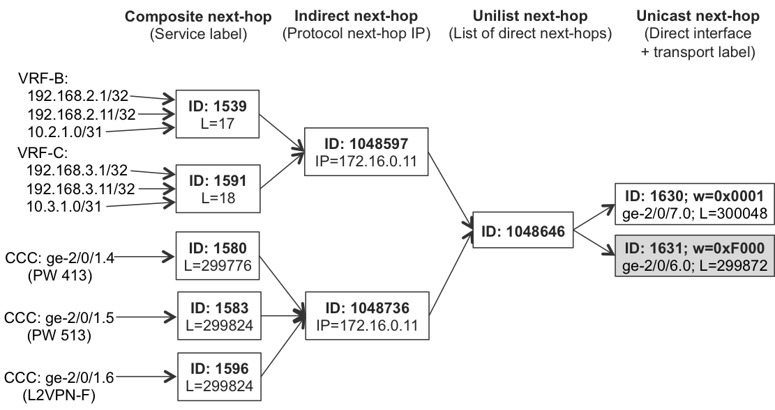
Figure 20-4. Hierarchical (chained composite next hop) FIB Structure on PE3 (Junos)
Chained composite next hop is disabled by default (except for Ethernet VPN [EVPN] where it is enabled by default) and must be explicitly enabled for the required address families, as shown in Example 20-5.
Example 20-5. Chained composite next hop configuration (Junos)
routing-options {
    forwarding-table {
        chained-composite-next-hop {
            ingress {
                l2vpn;
                l2ckt;
                l3vpn;
}}}}
Note
To completely reinitialize FIB structures, all BGP sessions are dropped and subsequently reestablished when chained composite next hop is enabled or disabled.
Let’s verify the states with operational commands for a couple of prefixes from different L3VPNs and other address families (LDP and BGP-based PWs); see Example 20-6.
Example 20-6. Chained composite next hop of prefixes advertised PE1→PE3 (Junos)
1     juniper@PE3> show route forwarding-table destination 192.168.2.1/32
2                  extensive | match "Destination|Index: [1-9]|weight|Push"
3     Destination:  192.168.2.1/32
4       Next-hop type: composite             Index: 1539     Reference: 6
5       Load Balance Label: Push 17, None
6       Next-hop type: indirect              Index: 1048597  Reference: 3
7       Next-hop type: unilist               Index: 1048646  Reference: 3
8       Next-hop type: Push 300048           Index: 1630     Reference: 1
9       Next-hop interface: ge-2/0/7.0  Weight: 0x1
10      Next-hop type: Push 299872           Index: 1631     Reference: 1
11      Next-hop interface: ge-2/0/6.0  Weight: 0xf000
12
13    juniper@PE3> request pfe execute target fpc2 command
14                 "show nhdb id 1539 recursive"
15    GOT: 1539(Compst, IPv4->MPLS, ifl:0:-, pfe-id:0, comp-fn:Chain)
16    GOT:  1048597(Indirect, IPv4, ifl:361:ge-2/0/7.0, pfe-id:0, i-ifl:0:)
17    GOT:     1048646(Unilist, IPv4, ifl:0:-, pfe-id:0)
18    GOT:       1630(Unicast, IPv4->MPLS, ifl:361:ge-2/0/7.0, pfe-id:0)
19    GOT:       1631(Unicast, IPv4->MPLS, ifl:381:ge-2/0/6.0, pfe-id:0)
20
21    juniper@PE3> show route forwarding-table destination 192.168.3.1/32
22                 extensive | match "Destination|Index: [1-9]|weight|Push"
23    Destination:  192.168.3.1/32
24      Next-hop type: composite             Index: 1591     Reference: 6
25      Load Balance Label: Push 18, None
26      Next-hop type: indirect              Index: 1048597  Reference: 3
27      Next-hop type: unilist               Index: 1048646  Reference: 3
28      Next-hop type: Push 300048           Index: 1630     Reference: 1
29      Next-hop interface: ge-2/0/7.0  Weight: 0x1
30      Next-hop type: Push 299872           Index: 1631     Reference: 1
31      Next-hop interface: ge-2/0/6.0  Weight: 0xf000
32
33    juniper@PE3> request pfe execute target fpc2 command
34                 "show nhdb id 1591 recursive"
35    GOT: 1591(Compst, IPv4->MPLS, ifl:0:-, pfe-id:0, comp-fn:Chain)
36    GOT:  1048597(Indirect, IPv4, ifl:361:ge-2/0/7.0, pfe-id:0, i-ifl:0:)
37    GOT:     1048646(Unilist, IPv4, ifl:0:-, pfe-id:0)
38    GOT:       1630(Unicast, IPv4->MPLS, ifl:361:ge-2/0/7.0, pfe-id:0)
39    GOT:       1631(Unicast, IPv4->MPLS, ifl:381:ge-2/0/6.0, pfe-id:0)
40
41    juniper@PE3> show route forwarding-table ccc ge-2/0/1.4 extensive |
42                 match "Destination|Index: [1-9]|weight|Push"
43    Destination:  ge-2/0/1.4  (CCC)
44      Next-hop type: composite             Index: 1580     Reference: 2
45      Load Balance Label: Push 299776, None
46      Next-hop type: indirect              Index: 1048736  Reference: 6
47      Next-hop type: unilist               Index: 1048646  Reference: 3
48      Next-hop type: Push 300048           Index: 1630     Reference: 1
49      Next-hop interface: ge-2/0/7.0  Weight: 0x1
50      Next-hop type: Push 299872           Index: 1631     Reference: 1
51      Next-hop interface: ge-2/0/6.0  Weight: 0xf000
52
53    juniper@PE3> request pfe execute target fpc2 command
54                 "show nhdb id 1580 recursive"
55    GOT: 1580(Compst, CCC->MPLS, ifl:0:-, pfe-id:0, comp-fn:Chain)
56    GOT:  1048736(Indirect, IPv4, ifl:361:ge-2/0/7.0, pfe-id:0, i-ifl:0:)
57    GOT:     1048646(Unilist, IPv4, ifl:0:-, pfe-id:0)
58    GOT:       1630(Unicast, IPv4->MPLS, ifl:361:ge-2/0/7.0, pfe-id:0)
59    GOT:       1631(Unicast, IPv4->MPLS, ifl:381:ge-2/0/6.0, pfe-id:0)
60
61    juniper@PE3> show route forwarding-table ccc ge-2/0/1.5 extensive |
62                 match "Destination|Index: [1-9]|weight|Push"
63    Destination:  ge-2/0/1.5  (CCC)
64      Next-hop type: composite             Index: 1583     Reference: 2
65      Load Balance Label: Push 299824, None
66      Next-hop type: indirect              Index: 1048736  Reference: 6
67      Next-hop type: unilist               Index: 1048646  Reference: 3
68      Next-hop type: Push 300048           Index: 1630     Reference: 1
69      Next-hop interface: ge-2/0/7.0  Weight: 0x1
70      Next-hop type: Push 299872           Index: 1631     Reference: 1
71      Next-hop interface: ge-2/0/6.0  Weight: 0xf000
72
73    juniper@PE3> request pfe execute target fpc2 command
74                 "show nhdb id 1583 recursive"
75    GOT: 1583(Compst, CCC->MPLS, ifl:0:-, pfe-id:0, comp-fn:Chain)
76    GOT:  1048736(Indirect, IPv4, ifl:361:ge-2/0/7.0, pfe-id:0, i-ifl:0:)
77    GOT:     1048646(Unilist, IPv4, ifl:0:-, pfe-id:0)
78    GOT:       1630(Unicast, IPv4->MPLS, ifl:361:ge-2/0/7.0, pfe-id:0)
79    GOT:       1631(Unicast, IPv4->MPLS, ifl:381:ge-2/0/6.0, pfe-id:0)
As you can see, the service label is moved out to the top of the next-hop hierarchy structure (lines 5, 25, 45, and 65). Furthermore, indirect next hop now represents the BGP protocol next hop plus address family, because L3VPN (lines 6 and 26) and L2VPN (lines 46 and 66) services are chained to another different indirect next hop. But what is even more important, in the case of PE3→P1 link or P1 node failure, removal of a single next hop (with ID 1630, lines 8, 28, 48, 68) is enough to fix all nine prefixes presented in Figure 20-4. This is especially important in scaled environments, with many hundreds of thousands of service prefixes. The repair action is really prefix-independent; it now depends only on the number of egress PEs reachable via the failed link.
In summary, chained composite next-hop hierarchy contains the following:
- Composite next hop
- For each service label, the FIB creates a separate composite next hop. This is true, as well, for L3VPN prefixes belonging to the same VRF but advertised from the egress PE with different VPN labels.
- Indirect next hop
- For each egress PE plus address family pair, the FIB creates separate indirect next hops. Indirect next hops are separate per address family, because packet encapsulation requirements might be different for each address family. Composite next hops for service labels from a common address family point to the same indirect next hop, forming the second level of a next-hop hierarchy.
- Unilist next hop
- For each egress PE, the FIB creates a single unilist next hop. All indirect next hops for a specific egress PE point to that unilist next hop. This is the third level of the next-hop hierarchy, resulting in a single next hop per egress PE, regardless of service labels and address families advertised by the egress PE.
- Unicast next hop
- Depending on the topology (load-balancing, protection) multiple direct unicast next hops might be present.
An additional benefit of using chained composite next-hop structures is more efficient usage of FIB resources. If you calculate next hops used in the indirect and composite next-hop schemes (Figure 20-3 and Figure 20-4), you will find that the number decreased from 20 to 10. Even with such a simple example with very limited number of prefixes, that difference is an impressive 50%.
BGP PIC Core (IOS XR)
BGP PIC Core is the IOS XR term that describes hierarchical next-hop structures programmed in the HW FIB. In principle, it is similar to the chained composite next-hop structures discussed earlier on the Junos platform; however, the terminology used is slightly different.
In IOS XR, hierarchical next-hop structures are enabled by default, therefore no special configuration is required. So, let’s verify the FIB states on PE2 (see Example 20-7).
Example 20-7. BGP PIC next hop for L3VPN routes announced PE4→PE2 (IOS XR)
1     RP/0/RSP0/CPU0:PE2#show cef 172.16.0.44/32 | include "  via|label"
2      via 10.0.0.27, Gi0/0/0/3, 3 dependencies, weight 0, class 0, backup
3       local label 16002      labels imposed {303200}
4     via 10.0.0.5, Gi0/0/0/2, 3 dependencies, weight 0, class 0, protected
5       local label 16002      labels imposed {302576}
6
7     RP/0/RSP0/CPU0:PE2#show cef vrf VRF-B 192.168.2.4/32 |
8                        include "  via|label|path-idx"
9      via 172.16.0.44, 4 dependencies, recursive [flags 0x6000]
10      path-idx 0 NHID 0x0 [0x72747364 0x0]
11       next hop 10.0.0.5/32 Gi0/0/0/2 labels imposed {302576 47}
12
13    RP/0/RSP0/CPU0:PE2# show cef vrf VRF-C 192.168.3.4/32 |
14                        include "  via|label|path-idx"
15     via 172.16.0.44, 4 dependencies, recursive [flags 0x6000]
16      path-idx 0 NHID 0x0 [0x72747364 0x0]
17       next hop 10.0.0.5/32 Gi0/0/0/2 labels imposed {302576 48}
18
19    RP/0/RSP0/CPU0:PE2#show cef vrf VRF-B 192.168.2.4/32 internal
20    (...)
21      label_info:[default [o-label:47 l-label:no-label type:0 (...)
22    (...)
23      [nh:172.16.0.44 ifh:NULLIFHNDL tbl:0xe0000000 (...)
24      [depth:2 flags:[recursive,resolved,ldi-preferred] resolves-via:
25        leaf:MPLS::0[0x71945050]:lsd:16002/0[(...)[0x72747364]
26    (...)
27          frr_nhinfo:[BKUP [type:prefix-backup link:link_MPLS
28            nh:10.0.0.27/32ifhandle:Gi0_0_0_3(0xe005640)
29            main-ifhandle:Gi0_0_0_3(0xe000680) tunid:0][0x72f11df0]
30    (...)
31          frr_nhinfo:[PROT [type:prefix-prot link:link_MPLS
32            nh:10.0.0.5/32ifhandle:Gi0_0_0_2(0xe0056c0)
33            main-ifhandle:Gi0_0_0_2(0xe000680) tunid:0][0x72f1268c]
34    (...)
35        0={
36            label_info:[default [o-label:303200 l-label:16002 (...)
37        1={
38            label_info:[default [o-label:302576 l-label:16002 (...)
PE2 can reach the PE4 loopback with the primary (lines 4 and 5) and LFA backup (lines 2 and 3) next hops. However, if you check the FIB entry for some VPN prefixes resolved via PE4 loopback, you will see only a single next hop (lines 10 and 11, and lines 16 and 17). At least the index of these next hops (lines 10 and 16) is the same, indicating that VPN prefixes from different VRFs (with different VPN label; lines 11 and 17) actually share the same FIB next-hop structure.
Missing a backup next hop is mysterious, however. Fortunately, this is just a cosmetic display issue. If you use the internal knob (line 19) to display FIB structure, you will get much more information, although some of it can be difficult to understand. By carefully reviewing this information, you can nonetheless reverse engineer the hierarchical FIB structure in IOS XR.
First of all, the outgoing service (VPN) label is at the top of the hierarchy (line 21). The prefix resolves via the PE4 loopback (line 23) with the BGP protocol next-hop index (line 25) matching the next-hop index observed previously (line 10 and 16). Next in the hierarchy you can see two IGP next hops: protected primary next hop (lines 31 through 33), and backup next hop (lines 27 through 29). Again, each next hop has an associated next-hop index. Further, you can discover outgoing labels associated with these IGP next hops (lines 36 and 38).
To save a few pages, other VPN prefixes (from VRF-B or VRF-C) reachable via PE4 are not displayed with the internal knob. However, the next-hop structures (next-hop indexes) are the same for all such prefixes. This confirms that IOS XR builds hierarchical next-hop FIB structures, as outlined in Figure 20-5.
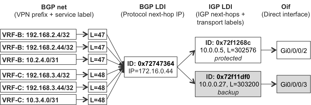
Figure 20-5. Hierarchical FIB structure for L3VPN on PE2 (IOS XR)
Each element in the hierarchy contains load information (LDI) with instructions required for proper traffic forwarding.
The next-hop structures for L2 services look similar to the ones for L3 services.
Example 20-8. PIC Core next hop for L2VPN routes advertised PE4→PE2 (IOS XR)
1     RP/0/RSP0/CPU0:PE2#show l2vpn forwarding interface Gi0/0/0/5.4
2                        hardware ingress location 0/0/CPU0 |
3                        include "State |--|mpls| ldi"
4     Segment 1                Segment 2                            State
5     ------------------------ ------------------------------------ ------
6     Gi0/0/0/5.4              mpls    172.16.0.44                  UP
7       XID: 0xc0008001, bridge: 0, MAC limit: 0, l2vpn ldi index: 0x0054,
8       vc label: 299840,
9
10    RP/0/RSP0/CPU0:PE2#show l2vpn forwarding interface Gi0/0/0/5.6
11                       hardware ingress location 0/0/CPU0 |
12                       include "State |--|mpls| ldi"
13    Segment 1                Segment 2                            State
14    ------------------------ ------------------------------------ ------
15    Gi0/0/0/5.6              mpls    172.16.0.44                  UP
16      XID: 0xc0008018, bridge: 0, MAC limit: 0, l2vpn ldi index: 0x0054,
17      vc label: 800003,
Now, instead of a BGP LDI index, the L2VPN LDI index is the same (lines 7 and 16), indicating shared a FIB next-hop structure, as illustrated in Figure 20-6.

Figure 20-6. Hierarchical (PIC Core) FIB structure for L2 services on PE2 (IOS XR)
Preinstalled Next Hops to Multiple Egress PEs (PIC Edge)
The previous section focused on the optimization of next-hop structures in FIB. During failure of upstream links or upstream nodes, the PE needs to remove only a limited number of primary next hops from its FIB. The number of primary next hops is independent from the number of prefixes. It depends only on the number of egress PEs, thus removal of the primary next hops from the FIB can be executed quite quickly.
In the previous section, all the examples were based on service prefixes (L3VPN, L2VPN) reachable via the single egress PE. However, to increase network resiliency, you can implement services in a redundant way, such that the CE device is dual-homed to two PE devices. If you look at Figure 20-1 again, this is the case for CE5-B/CE5-C and CE6-B/CE6-C. Prefixes belonging to CE5-B are advertised by both PE1 and PE2. PE3, after receiving these prefixes, performs a selection process and chooses one of them as the best. For example, via PE1, because the IGP cost from PE3 to PE1 is lower than that from PE3 to PE2. Only the best next hop is subsequently installed in the FIB structures discussed previously. Similarly, the CE5-B prefixes advertised by PE3 and PE4 arrive to PE2, but PE2 installs only one next hop in its FIB.
Let’s have a look at the RIB and FIB structures on PE3.
Example 20-9. RIB/FIB structures for CE5-B loopback on PE3 (Junos)
juniper@PE3> show route table VRF-B 192.168.2.5/32 active-path
(...)
192.168.2.5/32
     *[BGP/170] 00:08:44, MED 0, localpref 100, from 172.16.0.201
        AS path: ?, validation-state: unverified
      > to 10.0.0.8 via ge-2/0/7.0, Push 17, Push 300448(top)
        to 10.0.0.34 via ge-2/0/6.0, Push 17, Push 300144(top)

juniper@PE3> show route forwarding-table destination 192.168.2.5/32
             extensive | match "Destination|Index: [1-9]|weight|Push"
Destination:  192.168.2.5/32
  Next-hop type: composite             Index: 1572     Reference: 6
  Load Balance Label: Push 17, None
  Next-hop type: indirect              Index: 1048626  Reference: 3
  Next-hop type: unilist               Index: 1048703  Reference: 3
  Next-hop type: Push 300448           Index: 1598     Reference: 1
  Next-hop interface: ge-2/0/7.0  Weight: 0x1
  Next-hop type: Push 300144           Index: 1599     Reference: 1
  Next-hop interface: ge-2/0/6.0  Weight: 0xf000

juniper@PE3> request pfe execute target fpc2 command
             "show nhdb id 1572 recursive"
GOT: 1572(Compst, IPv4->MPLS, ifl:0:-, pfe-id:0, comp-fn:Chain)
GOT:  1048626(Indirect, IPv4, ifl:361:ge-2/0/7.0, pfe-id:0, i-ifl:0:)
GOT:     1048703(Unilist, IPv4, ifl:0:-, pfe-id:0)
GOT:       1598(Unicast, IPv4->MPLS, ifl:361:ge-2/0/7.0, pfe-id:0)
GOT:       1599(Unicast, IPv4->MPLS, ifl:381:ge-2/0/6.0, pfe-id:0)
Likewise, let’s verify that the RIB and FIB structures on PE2 IOS XR look very similar.
Example 20-10. RIB/FIB structures for CE6-B loopback on PE2 (IOS XR)
RP/0/RSP0/CPU0:PE2#show bgp vrf VRF-B 192.168.2.6/32 brief
(...)
   Network            Next Hop          Metric LocPrf Weight Path
Route Distinguisher: 172.16.0.22:102 (default for vrf VRF-B)
* i192.168.2.6/32     172.16.0.33            0    100      0 65506 ?
*>i                   172.16.0.44            0    100      0 65506 ?

RP/0/RSP0/CPU0:PE2#show route vrf VRF-B 192.168.2.6/32
(...)
Routing entry for 192.168.2.6/32
  Known via "bgp 65000", distance 200, metric 0
  Tag 65506, type internal
  Routing Descriptor Blocks
    172.16.0.44, from 172.16.0.201
      Nexthop in Vrf: "default", Table: "default", IPv4 Unicast,
        Table Id: 0xe0000000
      Route metric is 0
  No advertising protos.

RP/0/RSP0/CPU0:PE2#show cef vrf VRF-B 192.168.2.6/32
192.168.2.6/32, version 99, internal 0x5000001 0x0 (ptr 0x72189714)
 Prefix Len 32, traffic index 0, precedence n/a, priority 3
   via 172.16.0.44, 4 dependencies, recursive [flags 0x6000]
    path-idx 0 NHID 0x0 [0x726d2ca4 0x0]
    recursion-via-/32
    next hop VRF - 'default', table - 0xe0000000
    next hop 172.16.0.44 via 16075/0/21
     next hop 10.0.0.5/32 Gi0/0/0/2 labels imposed {300208 47}
What failover times can you expect during failure of the primary egress PE? Relatively long ones. Here’s why:
- IGP convergence
- The ingress PE must realize the failure of the primary egress PE. Typically, this is done by IGP. Upon primary egress PE failure, the IGP removes the primary egress PE loopback from the IGP database and the corresponding RIB and FIB structures on the ingress PE. IGP convergence is typically a few hundred milliseconds, and potentially, up to seconds in very large IGP domains.
- BGP convergence
- This time factor is more critical. After realizing primary egress PE failure, the ingress PE must remove indirect (recursive) next hops associated with the primary egress PE and then install a new, indirect (recursive) next hop associated with the backup egress PE. Again, this can take time. In highly scaled environments, it could take as long as several seconds.
How can you improve this? By preinstalling the next-hop structures associated with backup egress PE in the FIB. This concept has different flavors:
- Active/Standby
- Both next hops (toward primary and backup egress PE) are installed in the FIB. The next hop associated with the primary egress PE is used actively for forwarding, whereas the next hop associated with the backup egress PE is used only after detection of primary egress PE failure and the removal of primary egress PE next hop from the FIB. IOS XR calls this feature BGP PIC Edge Unipath; for Junos, it’s simply BGP PIC Edge. However, Junos uses
protect core(notprotect edge) to configure this feature. - Active/Active
- Both next hops (toward primary and backup egress PE) are installed in the FIB, if the BGP path selection considers both BGP updates (from primary and backup egress PE) as equal. This applies to IGP cost toward primary and backup egress PE, as well, which must be equal. The router actively uses both next hops for traffic forwarding, effectively performing load-balancing toward the primary and backup egress PE. IOS XR calls this feature BGP PIC Edge Multipath, whereas Junos calls it simply VPN Multipath. Optionally, both IOS XR and Junos support unequal-cost multipath, wherein IGP cost to the egress PE is not taken into account by the BGP path selection process.
Active/Standby Next Hops to Egress PEs
Let’s first configure Active/Standby next-hops to egress PEs (see Examples Example 20-11 and Example 20-12).
Example 20-11. Configuration of Active/Standby next hops to egress PEs on IOS XR
route-policy PL-BGP-BACKUP-PATH
  set path-selection backup 1 install
end-policy
!
router bgp 65000
 vrf VRF-B
  address-family ipv4 unicast
   additional-paths selection route-policy PL-BGP-BACKUP-PATH
Example 20-12. Configuration of Active/Standby next hops to egress PEs on Junos
routing-instances {
    VRF-B {
        routing-options {
            protect core;
}}}
By examining the following FIB next-hop structures, you can confirm that indeed both Junos and IOS XR installed a backup next hop pointing to a backup egress PE in the FIB.
Example 20-13. FIB structures for CE5-B loopback on PE3 (Junos)
1     juniper@PE3> show route forwarding-table destination 192.168.2.5/32
2                  extensive | match "Destination|Index: [1-9]|weight|Push"
3     Destination:  192.168.2.5/32
4       Next-hop type: unilist               Index: 1048685  Reference: 1
5       Next-hop type: composite             Index: 1554     Reference: 6
6       Load Balance Label: Push 17, None
7       Next-hop type: indirect              Index: 1048623  Reference: 3
8                                         Weight: 0x1
9       Next-hop type: unilist               Index: 1048703  Reference: 3
10      Next-hop type: Push 300448           Index: 1598     Reference: 1
11      Next-hop interface: ge-2/0/7.0    Weight: 0x1
12      Next-hop type: Push 300144           Index: 1599     Reference: 1
13      Next-hop interface: ge-2/0/6.0    Weight: 0xf000
14      Next-hop type: composite             Index: 1582     Reference: 2
15      Load Balance Label: Push 16101, None
16      Next-hop type: indirect              Index: 1048621  Reference: 8
17                                        Weight: 0x4000
18      Next-hop type: unilist               Index: 1048707  Reference: 3
19      Next-hop type: Push 300464           Index: 1664     Reference: 1
20      Next-hop interface: ge-2/0/7.0    Weight: 0x1
21      Next-hop type: Push 300160           Index: 1665     Reference: 1
22      Next-hop interface: ge-2/0/6.0    Weight: 0x1
23
24    juniper@PE3> request pfe execute target fpc2 command
25                 "show nhdb id 1048685 recursive"
26    GOT: 1048685(Unilist, IPv4, ifl:0:-, pfe-id:0)
27    GOT:   1554(Compst, IPv4->MPLS, ifl:0:-, pfe-id:0, comp-fn:Chain)
28    GOT:     1048623(Indirect, IPv4, ifl:361:ge-2/0/7.0, pfe-id:0)
29    GOT:       1048703(Unilist, IPv4, ifl:0:-, pfe-id:0)
30    GOT:         1598(Unicast, IPv4->MPLS, ifl:361:ge-2/0/7.0, pfe-id:0)
31    GOT:         1599(Unicast, IPv4->MPLS, ifl:381:ge-2/0/6.0, pfe-id:0)
32    GOT:   1582(Compst, IPv4->MPLS, ifl:0:-, pfe-id:0, comp-fn:Chain)
33    GOT:      1048621(Indirect, IPv4, ifl:361:ge-2/0/6.0, pfe-id:0)
34    GOT:        1048707(Unilist, IPv4, ifl:0:-, pfe-id:0)
35    GOT:          1664(Unicast, IPv4->MPLS, ifl:361:ge-2/0/7.0, pfe-id:0)
36    GOT:          1665(Unicast, IPv4->MPLS, ifl:381:ge-2/0/6.0, pfe-id:0)
Example 20-14. FIB structures for CE6-B loopback on PE2 (IOS XR)
1     RP/0/RSP0/CPU0:PE2#show route vrf VRF-B 192.168.2.6/32 | include from
2         172.16.0.33, from 172.16.0.201, BGP backup path
3         172.16.0.44, from 172.16.0.201
4
5     RP/0/RSP0/CPU0:PE2#show cef vrf VRF-B 192.168.2.6/32 |
6                        include "  via|label|path-idx"
7     (...)
8        via 172.16.0.33, 5 dependencies, recursive, backup [flags 0x6100]
9         path-idx 0 NHID 0x0 [0x726d2d10 0x0]
10         next hop 10.0.0.27/32 Gi0/0/0/3 labels imposed {300432 37}
11         next hop 10.0.0.5/32 Gi0/0/0/2 labels imposed {300128 37}
12       via 172.16.0.44, 6 dependencies, recursive [flags 0x6000]
13        path-idx 1 NHID 0x0 [0x72747364 0x0]
14        next hop 10.0.0.5/32 Gi0/0/0/2 labels imposed {302576 47}
Let’s use Figure 20-7 to interpret the next-hop structures displayed in Example 20-13.
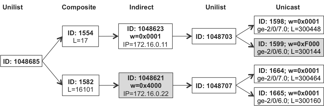
Figure 20-7. FIB structures with Active/Standby egress PE next hops on PE3 (Junos)
In the case of Junos (Example 20-13), you can see the hierarchical next-hop hierarchy with five levels (lines 24 through 36). Junos differentiates between the primary (lines 7, 8, and 28) and the backup (lines 16, 17, and 33) egress PE with different weights (0x0001 versus 0x4000). Furthermore, different weights are applied to the final, direct unicast next hops (0x0001 + 0xF000 versus 0x0001 + 0x0001). Thus, traffic to the primary egress PE (PE1, IGP cost PE3→PE1=20) uses only one link (the second link is simply backup) and—after failure of PE1—traffic to the backup egress PE (PE2, IGP cost PE3→PE2=21) is load-balanced. This is correct, and reflects the IGP metrics used in the topology.
IOS XR (see Example 20-14 and Figure 20-8) behaves in a similar way in principle. However, as already discussed in the BGP PIC Core section, Cisco Express Forwarding (CEF) for VRF prefixes does not display backup LFA next hops. You need to use the internal knob with the show cef vrf command to see the full picture (it is omitted here, though, to save space).
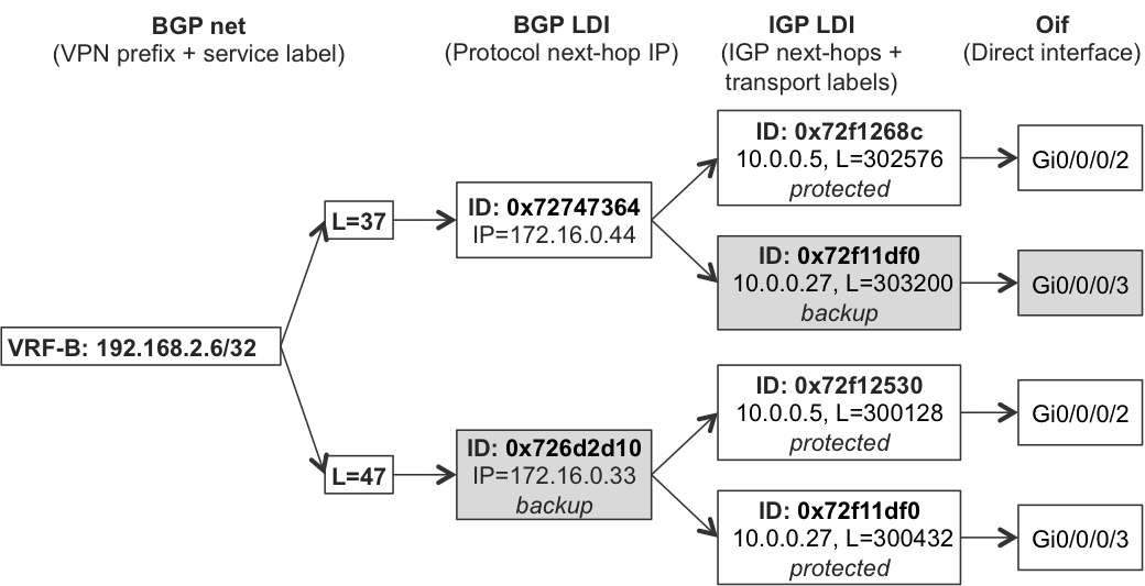
Figure 20-8. FIB structures with Active/Standby egress PE next hops on PE2 (IOS XR)
Active/Active Next Hops to Egress PEs
You can deploy Active/Active next hops to egress PEs in two variants, as mentioned earlier: equal-cost and unequal-cost. From a configuration perspective, multipath must be enabled in the respective VRFs, in both IOS XR and Junos, as presented next.
Example 20-15. Configuration of Active/Active next hops to egress PEs on IOS XR
router bgp 65000
  vrf VRF-C
    address-family ipv4 unicast
      maximum-paths ibgp 4 unequal-cost   !! unequal-cost optional
Example 20-16. Configuration of Active/Active next hops to egress PEs on Junos
routing-instances {
    VRF-C {
        routing-options {
            multipath {
                vpn-unequal-cost;          ## vpn-unequal-cost optional
}}}}
Note
For multipath to work, the BGP selection process must consider BGP updates received from two egress PEs as equal. Specifically, if mixed Junos and IOS XR–based PEs are used, the values of MED and ORIGIN attributes must be unified (the same values advertised by both vendors’ PEs), because the default values are different.
Outputs of the verification commands as well as the hierarchical next-hop structures are very similar to those presented in the previous section (see Examples Example 20-13 and Example 20-14). In Junos, the difference is simply in the weights of indirect next hops (the weight is now 0x0000 for both the indirect next hops), which results in load-balancing of traffic toward two egress PEs. In IOS XR, both paths are marked as bgp-multipath instead of one path being marked as backup—again resulting in load-balancing toward the two egress PEs. Let’s see that.
Example 20-17. FIB structures for CE5-C loopback on PE3 (Junos)
juniper@PE3> show route forwarding-table destination 192.168.3.5/32
             extensive | match "Destination|Index: [1-9]|weight|Push"
(...)
  Next-hop type: indirect              Index: 1048623  Reference: 3
                                    Weight: 0x0
(...)
  Next-hop type: indirect              Index: 1048621  Reference: 8
                                    Weight: 0x0
(...)
Example 20-18. FIB structures for CE6-C loopback on PE2 (IOS XR)
RP/0/RSP0/CPU0:PE2#show cef vrf VRF-C 192.168.3.6/32 |
                   include recursive
   via 172.16.0.33, 6 dependencies, recursive, bgp-multipath
   via 172.16.0.44, 6 dependencies, recursive, bgp-multipath
Note
When Active/Active and Active/Standby mode are configured together, both Junos and IOS XR try first to install multiple next hops in Active/Active mode if possible. For example, if Active/Active mode with equal-cost multipath is configured but IGP cost to egress PEs is not equal, the Active/Standby mode is used.
The traceroutes shown in Example 20-19 and Example 20-20 confirm that in VPN-B (configured for Active/Standby) no load-balancing between the two egress PEs takes place, whereas in VPN-C (configured for Active/Active) traffic is load-balanced toward the two egress PEs:
Example 20-19. Traceroute with Active/Standby next hops to egress PEs
juniper@CE5-B> traceroute 192.168.2.6
traceroute to 192.168.2.6 (192.168.2.6), 30 hops max, 40 byte packets
 1  PE2-VRF-B (10.2.5.2)  1.123 ms  0.827 ms  0.847 ms
 2  P1 (10.0.0.5)  0.690 ms  0.688 ms P2 (10.0.0.27)  1.011 ms
     MPLS Label=300496 CoS=0 TTL=1 S=0
     MPLS Label=37 CoS=0 TTL=1 S=1
 3  PE3-VRF-B (192.168.2.33)  0.715 ms  0.618 ms  0.595 ms
 4  CE6-B (10.2.6.6)  1.415 ms *  1.554 ms

RP/0/RSP0/CPU0:CE6-B#traceroute 192.168.2.5
 1  10.2.6.3 0 msec
    10.2.6.4 0 msec  0 msec
 2  10.0.0.8 [MPLS: Labels 300544/16099 Exp 0] 0 msec  0 msec
    10.0.0.10 0 msec
 3  10.0.0.4 [MPLS: Label 16099 Exp 0] 0 msec  0 msec     ## PE2
    10.0.0.26 0 msec                                      ## PE2
 4  192.168.2.5 0 msec  0 msec  0 msec
Example 20-20. Traceroute with Active/Active next hops to egress PEs
juniper@CE5-C> traceroute 192.168.3.6
traceroute to 192.168.3.6 (192.168.3.6), 30 hops max, 40 byte packets
 1  PE2-VRF-C (10.3.5.2)  1.366 ms  0.864 ms  1.316 ms
 2  P1 (10.0.0.5)  0.722 ms  0.630 ms P2 (10.0.0.27)  0.645 ms
     MPLS Label=300496 CoS=0 TTL=1 S=0
     MPLS Label=48 CoS=0 TTL=1 S=1
 3  192.168.3.44  0.633 ms  0.602 ms 192.168.3.33  0.645 ms
 4  CE6-C (10.3.6.6)  1.568 ms *  1.462 ms

RP/0/RSP0/CPU0:CE6-C#traceroute 192.168.3.5
 1  10.3.6.3 1 msec
    10.3.6.4 0 msec  0 msec
 2  10.0.0.10 [MPLS: Labels 300288/16102 Exp 0] 0 msec
    10.0.0.32 0 msec
    10.0.0.8 0 msec
 3  10.0.0.26 [MPLS: Label 16102 Exp 0] 0 msec  0 msec     ## PE2
    192.168.3.11 0 msec                                    ## PE1
 4  192.168.3.5 0 msec  0 msec  0 msec
BGP Best External Failover
Installing next hops to multiple egress PEs (in Active/Active or Active/Standby mode) requires, obviously, that the ingress PE has information about the prefix from these egress PEs. If, for whatever reason, the ingress PE has updates from the single egress PE, the multiple next hops are not possible.
Now, if you want to deploy the PE3/PE4 router pair in primary/backup fashion, you can, for example, increase local preference for prefixes advertised by PE3 so that prefixes from PE3 are preferred over prefixes from PE4. However, when you verify the routing state in ingress PE, you will realize that the ingress PE (e.g., PE2) no longer has information from the backup egress PE (PE4).
Example 20-21. RIB entry for CE6-B loopback on PE2 (IOS XR)
RP/0/RSP0/CPU0:PE2#show route vrf VRF-B 192.168.2.6/32 | include from
    172.16.0.33, from 172.16.0.201
If you compare the current RIB state (Example 20-21), with the RIB state observed previously (lines 1 through 3 in Example 20-14), you will clearly see the missing information from PE4. So, what happened? Well, let’s check the states on PE4.
Example 20-22. RIB entry for CE6-B loopback on PE4 (Junos)
1     juniper@PE4> show route table VRF-B 192.168.2.6/32 detail |
2                  match "Pref|reason|Protocol next hop|Source"
3          *BGP    Preference: 170/-201
4                  Source: 172.16.0.201
5                  Protocol next hop: 172.16.0.33
6                  Localpref: 200
7           BGP    Preference: 170/-201
8                  Source: 172.16.0.202
9                  Protocol next hop: 172.16.0.33
10                 Inactive reason: Not Best in its group - Update source
11                 Localpref: 200
12          BGP    Preference: 170/-101
13                 Source: 10.2.6.6
14                 Inactive reason: Local Preference
15                 Localpref: 100
PE4 receives updates about the CE6-B loopback from three sources, including two updates from the route reflectors (lines 3 through 11), which are reflecting the original update from PE3. It is visible from the protocol next hop, which is the PE3 loopback (lines 5 and 9). These two updates are in principle the same, only the update sources (lines 4 and 8) are different (RR1 and RR2). The third update (lines 12 through 15) is received directly from CE6-B (line 13).
Now, as discussed previously, the configuration for PE3 is temporarily changed so that PE3 advertises the updates with the higher (200) local preference (lines 5 and 10), whereas CE6-B updates inherits the default (100) local preference (line 15). Therefore, the update from PE3 (reflected by two Route Reflectors [RRs]) is preferred over the update received directly from CE6-B (line 14). Consequently, PE4 does not use the update from CE6-B for routing or forwarding—this update remains inactive.
This is the problem. The update from CE6-B is inactive on PE4, therefore PE4 does not send this update to the RRs, and thus PE2 does not receive updates from PE4. So, PE2 cannot install the second next hop in its FIB, as PE2 is not even aware that CE6-B connects not only to PE3, but also to PE4.
Such a scenario is very typical in real deployments, not only in L3VPN designs, but in plain Internet designs as well. Service providers or big enterprises receive Internet feeds over multiple Internet gateways (egress PEs). If the Internet gateways are configured in primary/backup fashion, only prefixes from primary Internet gateways are visible to the rest of the network, preventing the BGP PIC Edge from functioning.
Now, what can you do? You can implement a slight modification to the BGP behavior, as described in draft-ietf-idr-best-external. In principle, with this small modification, BGP advertises the best external route, even when that external route is not active; for example, when a BGP internal route is better. This modification does not only allow proper functionality for the BGP PIC Edge in primary/backup PE deployments, it also helps to reduce interdomain churn (Section 9 of the Draft) and persistent IGP route oscillation (Section 10 of the Draft).
Therefore, let’s enable this feature on all PEs, including PE4.
Example 20-23. Advertise best external path configuration on Junos
protocols {
    bgp {
        group IBGP-RR {
            advertise-external;
}}}
Example 20-24. Advertise best external path configuration on IOS XR
router bgp 65000
 address-family vpnv4 unicast
  advertise best-external
After these configuration changes, nothing changes on PE4 from a forwarding perspective: the update from CE6-B is still inactive. However, PE4 starts to advertise this inactive update toward the route reflectors, so it arrives at PE1 and PE2, making pre-installation of the backup next hop possible.
Example 20-25. RIB entry for CE6-B loopback on PE2 (IOS XR)
RP/0/RSP0/CPU0:PE2#show route vrf VRF-B 192.168.2.6/32 | include from
    172.16.0.33, from 172.16.0.201
    172.16.0.44, from 172.16.0.201, BGP backup path
Understanding the next-hop structures is a great preparation for the next chapter, which focuses on the egress protection feature set.