
Lead–acid batteries for hybrid electric vehicles and battery electric vehicles
J. Garche1; P.T. Moseley2; E. Karden3 1 FCBAT Ulm, Ulm, Germany
2 ILZRO, Chilton, UK
3 Ford Research & Advanced Engineering Europe, Aachen, Germany
Abstract
This chapter provides a description of the working principles of the lead–acid battery (LAB) and its characteristic performance properties such as capacity, power, efficiency, self-discharge rate, and durability. Environmental and safety aspects are discussed, and it is made clear that the battery can be employed safely and sustainably as long as appropriate precautions are observed. A central theme of the chapter is a consideration of the diverse types of battery—starting, lighting, and ignition (SLI), enhanced flooded battery, and absorptive glass mat—that have been developed for different automotive applications such as SLI and stop–start operation in microhybrids. In this latter connection it has been recognized that the inclusion of carbon integrated into the negative plate of the battery in different ways can give rise to a huge improvement in performance. It is pointed out that batteries deploying the lead–acid chemistry in the microhybrid application have the lowest specific additional cost for the reduction of carbon dioxide emissions (€/% CO2 reduction). An application of lead–acid in mild hybrids (12 V or even 48 V) would be possible if the dynamic charge acceptance and the total cycling throughput could be improved. The use of advanced LABs in dual systems with lithium-ion batteries would also be possible. Potential further improvements of the battery (e.g., through the use of optimized grids, bipolar designs, or additives) is discussed as is the use of LABs in engine downsize and boost concepts. A market forecast showing that in 2020 more than 50% of all cars will be microhybrids with LABs rounds off the chapter.
5.1 Introduction
The lead–acid battery (LAB) has already benefited from more than 150 years of technical development. Gaston Planté built the first LAB in 1859 when he took two lead sheets separated by rubber strips, rolled them into a spiral, immersed them in a sulfuric acid electrolyte, and formed them by applying a direct current. In 1881 Camille Alphonse Fauré introduced pasted plates, and in 1890 Donato Tomassi and H. Woodward produced the first tubular plate design (Garche, 1990).
Whereas the chemistry of the system described by the double sulfate theory of Gladstone and Tribe (1882) has remained unchanged, the plate and cell designs have been continuously improved.
The main applications have been for stationary energy storage and, with the introduction of electric starting cars (since 1912), the starter battery, which must also provide the lighting and ignition functions (starting, lighting, and ignition—SLI battery). A new application with great market potential has emerged with the introduction of micro- and mild-hybrid cars.
Despite recent growth of advanced battery chemistries, the LAB still accounts for more than 50% of the global rechargeable battery market in terms of US dollar value, and for more than 80% in terms of GWh cell production (Pillot, 2014). This dominance is due to the low specific cost of the raw materials, the mature and cost-optimized manufacturing technology, the robustness of the battery, its low-temperature discharge power, heat tolerance, and low self-discharge together with an established recycling technology.
The uptake of the technology is somewhat limited by the relatively low specific energy and power of the system that stem from the high specific gravity of lead; a low deep-cycle life as a result of the solution-precipitation mechanisms; limited charge acceptance leading to gas development during charging, and stratification and sulfation that occur because the electrolyte is an active component in the charge and discharge reactions.
5.2 Technical description of the LAB
5.2.1 Fundamental principles
The operating principle of the LAB, following the Gladstone and Tribe scheme, is as follows:
Negative electrode
Positive electrode
Cell
where φo and Uo represent the electrode potential (φ) and the cell voltage (U), respectively, for the standard state (concentration ≈ activity = 1), that is, approximately ![]() . In practice, higher sulfuric acid concentrations are used: 5.0–6.3 mol/L, 33–38% acid strength, and 1.24–1.28 g/cm3 specific gravity, so that practical cell voltages are higher. During discharge the sulfuric acid concentration is reduced, and the cell voltage is decreased in accordance with the Nernst equation. An empirical equation for the dependence of the open circuit cell voltage (Uo) on sulfuric acid concentration (in practice generally measured as density) is as follows:
. In practice, higher sulfuric acid concentrations are used: 5.0–6.3 mol/L, 33–38% acid strength, and 1.24–1.28 g/cm3 specific gravity, so that practical cell voltages are higher. During discharge the sulfuric acid concentration is reduced, and the cell voltage is decreased in accordance with the Nernst equation. An empirical equation for the dependence of the open circuit cell voltage (Uo) on sulfuric acid concentration (in practice generally measured as density) is as follows:
The LAB cell voltage (> 2 V) is higher than the decomposition voltage of water (> 1.23 V), which is a major component of the electrolyte (aqueous sulfuric acid). Therefore, the following corrosion reactions (local element reactions) are thermodynamically favorable and should lead to self-discharge of the active masses of the electrodes:
Negative electrode
Positive electrode
The reaction rates of these self-discharge processes, however, are very low due to the high overpotentials for the gas evolution reactions. For self-discharge data see Section 5.2.3.2.
The above gas evolution reactions are equivalent to the overcharge reactions at the negative and positive electrodes, respectively:
Negative electrode
Positive electrode
As a result of this tendency to produce gases the LAB has, historically, not been sealed. The cell is equipped with a screw lid, which is gas- and partially liquid-permeable. Such cells are referred to as “flooded cells.”
Much effort has been expended in the past to find a way to close the cell without an unacceptable increase in pressure. This challenge was resolved with the aid of the oxygen recombination cycle: if oxygen developed at the positive electrode is able to reach the negative electrode, then the main overcharge reaction at the negative electrode is an oxygen reduction:
This is the result of the more positive potential of the oxygen reduction as compared with that of hydrogen evolution.
The reactions in the overcharge phase are in this case
Positive electrode
Negative electrode
and therefore the overall cell reaction is zero.
For practical use of this phenomenon, the oxygen must be transported from the positive electrode to the negative electrode. Diffusion of oxygen through the liquid phase is rather slow so the mass transport depends on immobilization of the electrolyte on inert separator materials with high surface areas. Small gas channels are created within the separator material, and these allow the oxygen transport to take place through the gas phase.
As a result, the LAB can be closed but not hermetically sealed. If the oxygen evolution reaction at the positive electrode becomes much higher than the oxygen reduction at the negative, a gas pressure is built up in the cell. A gas valve integrated into the cell lid is able to release excess pressure to the external atmosphere. Batteries comprising cells operating the oxygen recombination cycle are therefore called valve-regulated lead–acid (VRLA) batteries or sealed lead–acid (SLA) batteries.
Silica is the principal absorbent material used for the immobilization of the electrolyte. In one case the silica is porous, with an agglomerate diameter of 10–250 μm. The silica forms a gel with the electrolyte so that this VRLA battery variant is known as the gel type. In another case silica glass fibers with a diameter of 0.6–6 μm, arranged in a paper-like glass mat with a thickness of 1–4 mm are used. The VRLA battery with this glass mat separator is called absorbent glass mat (AGM) type.
5.2.2 Design
As previously mentioned, there are many electrode designs for the LAB. For stationary industrial applications with high lifetime requirement, the Planté-type negative electrode is used; a high-surface-area compact lead active mass is formed electrochemically. The so-called tubular type electrode (Figure 5.1) is used for the positive.

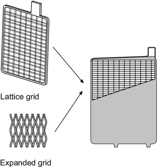
For automotive and transportation applications where power, weight, and costs are limiting factors, grid-type electrodes (Figure 5.2) are mostly used. The grid (cast, punched, or expanded) is pasted with precursor materials, which are then cured and formed into the final active masses.
Normally the positive and negative grids are kept apart by a separator and are stacked together to form a cell block, which is housed in a plastic compartment equipped with a cell plug. Normally six such compartments are contained in a battery monobloc case so that the battery has an open circuit voltage just above 12 V. In most cases the container has a central volume where the gases collected from all six cells are vented through a porous flame arrestor frit, which retains acid fumes and protects against ignition by external sparks (see Figure 5.3).

In some cases the plates will be spiral-wound (see Figure 5.4).

The spiral-wound configuration brings with it a high mechanical stability for the cell, and this allows the use of pure lead (99.999%), which has an inherently low mechanical stability but high corrosion resistance. In this way a high operating lifetime can be achieved.
The prismatic configuration shown in Figure 5.3 can be used for
∙ gel-type cells,
∙ AGM-type cells,
whereas the spiral-wound type is used mainly for AGM-type cells alone.
Currently automotive batteries are usually 12 V (six cell) monobloc units of either the flooded or the AGM design. Capacities (measured at the 20 h rate) range from about 25 to 110 Ah for cars, depending on size and the demands of electric accessories, and up to about 250 Ah for trucks. For heavy-duty commercial vehicles in Europe, the SLI battery nominal voltage has been established as 24 V (primarily driven by the cold cranking power demand), which is realized by two 12 V batteries of typically 150 Ah or higher capacity connected in series. In contrast, North American trucks historically used two 12 V units connected in parallel to enhance cranking power and capacity.
5.2.3 Electrical performance
5.2.3.1 Capacity, power, and efficiency
In contrast to the lithium-ion battery the capacity of the LAB depends strongly on the discharge current as shown in Figure 5.5.
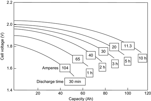
The relationship between the capacity and the discharge current is empirically described by the Peukert equation:
where C symbolizes the capacity of the battery (Ah) at constant discharge current I, k is the Peukert constant, and t is the total discharge time.
The Peukert constant k (≥ 1) provides an indication of the internal resistivity and therefore of the power capability of the cell. The smaller the value of k, the higher the power capability. The value of k for flooded batteries lies within the range 1.2–1.5. For gel batteries the range is from 1.1 to 1.25 and for AGM batteries from 1.05 to 1.15. Thus, the AGM battery has the highest power capability of the three designs.
The constant k increases with the age of the battery but decreases with increasing temperature signifying a capacity increase. The capacity increase is caused by a decrease of the internal resistance that results from an increase of mass transfer rates. Unfortunately not only are the rates of the main reaction increased but also those of life-limiting side reactions such as corrosion.
The energy efficiency of the LAB is given by the relationship of the discharged energy to the charged energy and is the product of the Ah-efficiency (Ahdischarged/Ahcharged) and the voltage-efficiency (Udischarged/Ucharged). Gas generation at the electrodes commences before the cell is fully charged so the Ah-efficiency is only in the region of 85%. Relatively high overpotentials during discharge and charge lead to a voltage efficiency of about 80%, so that the energy efficiency under normal operation conditions is around 70%. The values given here are only guidelines and strongly depend on the charge and discharge currents and the temperature.
5.2.3.2 Self-discharge
In general, the self-discharge of the LAB at room temperature is between 2% and 5% per month (see Figure 5.6).
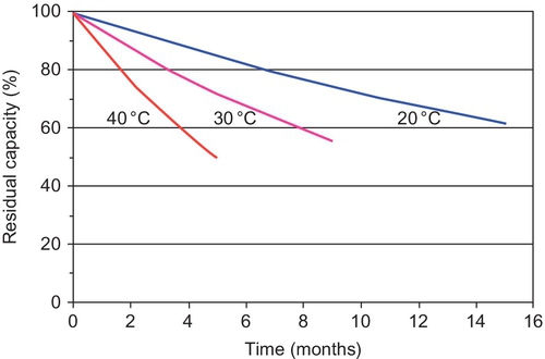
The self-discharge rate will increase with temperature and as a result of impurities that could be introduced into the system during grid corrosion (especially where antimony grids are used) or from the use of nondistilled water in the case of flooded batteries.
Batteries with lead-antimony grids show faster self-discharge (2–10%/week depending on the Sb concentration) than those with lead-calcium grids, but they have a long lifespan, owing to the low rate of corrosion of the PbSb alloy.
Self-discharge proceeds with low currents and leads to the formation of large PbSO4 crystals. Such crystals are difficult to charge so that the electrode becomes “sulfated” if self-discharge is allowed to proceed unchecked. To avoid damage from sulfation a trickle charge is used with a current commensurate with the self-discharge current.
5.2.3.3 Durability
Apart from catastrophic failures, the operating life of the LAB is determined by continuous aging factors such as grid corrosion, active mass degradation (mostly sulfation or loss of integrity), separator degradation, and/or drying out. The impact of these factors on the life of the battery depends on the cell design (e.g., plate thickness) and operating parameters (e.g., charge/discharge currents, state of charge (SoC), temperature).
Plate thickness
One of the main life-determining factors of automotive batteries is positive grid corrosion. The positive grid will be “eaten away” over the time by corrosion. Therefore, a thicker grid will increase operating life, but at the expense of specific energy (Wh/kg). Thicker active material layers can also lead to higher life time—in cases where mass-shedding is the life-limiting process. Automotive batteries typically have plates about 1 mm thick (including grid and active material), and forklift batteries may have plates ≥ 7 mm thickness.
Depth of discharge and dynamic charge acceptance
The charge/discharge reactions of the LAB take place via dissolution and precipitation steps with large volume changes between reactants and products leading to internal mechanical stress, which gives rise to a partial decomposition of the original structure and an increase of the internal resistance. This effect is greater, the deeper is the depth of discharge (DoD). Lifetime is reduced with increasing DoD as shown in Figure 5.7.

To achieve a long life the DoD should be limited as much as the application will allow.
The range of SoC exploited in different applications is shown schematically in Figure 5.8.

The conventional SLI battery normally remains within an SoC range above around 80%. If the SLI battery, which is designed for high power and low cost, was to be set to perform full cycles then its cycle life would be only around 50 cycles.
For electric vehicle (EV) and industrial (stationary energy storage) applications the battery is designed for deep discharge, with thicker plates and/or tubular type positive electrodes (see Figure 5.1).
A special problem arises in full or mild hybrid electric vehicle (HEV) applications, which have been, up to now a domain of NiMH and Li-ion batteries. In both applications, the operating window of SoC lies typically between about 70% (above which level even high-power batteries lose their fast charge capability that enables full regenerative braking functionality) and about 40% (below which level discharge power, and thus propulsion functionality, would be compromised, as well as durability because of aging processes facilitated by deep discharge). Thus, the HEV battery is normally not operated near its fully charged state. When conventional LABs are exposed to this partial state-of-charge (PSoC) regime, they fail rapidly as a result of sulfation of the negative plate. Furthermore, if the battery is left at a PSoC for a significant length of time, lead sulfate crystals have the opportunity to grow progressively by the process of Ostwald ripening.
Restoration of the primary fine crystal structure of the active mass, which is necessary for optimal capacity to be sustained, depends on the battery being taken to a full SoC. If, however, a full SoC is never reached, some of the PbSO4 discharge product will remain and its crystal size will increase. During high rate operation (HEVs require brief charge events at up to ~ 30 times the 1 h rate), these large PbSO4 crystals form layers initially at the electrode surface (see Figure 5.9, 1735 cycles). With increasing operating time the layer will be extended to the inner regions of the electrode (see Figure 5.9, 3191 cycles). As the charge current cannot be accommodated by the reaction that reduces PbSO4 to Pb, the negative plate potential shifts to a more negative value, and hydrogen evolution increases.

This result of high-rate PSoC operation, that is, the reduced charge acceptance, leads to a rapid capacity loss and short life when conventional LABs are used.
The impact of this mode of operation can be reduced if the electrochemical reactions (charge/discharge) are distributed over the whole electrode thickness and the whole of the plate area homogeneously rather than on the plate surface and near the current take-off lug. More homogeneous current distribution can be achieved by an optimal grid design and by the incorporation of certain forms of extra carbon on the negative plate.
The storage system in microhybrid vehicles has to carry over all the SLI battery functions, including cold cranking and standby energy for parking and potential alternator failure. Nevertheless, brake energy recuperation has to be enabled by PSoC operation. Consequently, the SoC operating window for micro-HEV batteries is shifted upward to a range between 75% and 90% (actually even smaller for a given vehicle application, temperature, and perhaps other usage conditions that the automaker's alternator regulation strategy might take into account). This operating range accompanies a significantly lower power/energy ratio required by the shallow cycling profiles caused by stop/start and recuperation in microhybrids, compared to mild and full hybrids. For example, a 36-s idle-off or recuperation event with 60 A for a 60 Ah battery would cause only a 1% Cn energy turnover. Both parameters given in the above example exceed the typical duration and stop-load or recuperation currents, respectively (i.e., typical DoD in microhybrids is well below 1%). As a consequence, cyclic wear is not massively accelerated and still allows the use of (enhanced) flooded batteries in most microhybrid car applications, but sulfation due to progressive undercharging may become a significant issue. Such undercharging would not typically lead to an early failure in terms of cranking performance or capacity but would limit the real-world fuel savings by regenerative braking, delay the SoC recovery after stop/start or key-off discharge events, and reduce the availability of the stop/start function. These effects have been observed for both flooded and AGM-type automotive batteries, and sometimes termed lazy battery phenomenon.
In both mild and microhybrid applications, or from a battery perspective, in partial cycling applications, the ability of the battery to robustly absorb high charging currents has become crucial. It has been proposed to call this performance attribute dynamic charge acceptance (DCA; Karden et al., 2005), and for the first time it will become part of a battery standard in the new European norm on 12 V microhybrid batteries (Standards Development, 2014). It should be emphasized that the sluggishness and inconsistency (strong dependence on short-term cycling history) of DCA is a technology-specific issue of LABs, no matter whether flooded or valve-regulated but rarely encountered with other storage technologies. Mechanistically, it can be explained with the dissolution of lead sulfate being the rate-determining step of the charging reaction, which is independent of the applied potential (Sauer et al., 2007) and is aggravated by acid stratification in flooded batteries (Ebner et al., 2013). Modifications of the negative electrode, either macroscopically or microscopically, have proven to enable a substantially enhanced DCA and will be discussed below.
Temperature
As already mentioned, the rates of the charge/discharge reactions are increased with increasing temperature but so too are the rates of life-limiting side-reactions such as corrosion.
The optimum operating temperature range for the LAB is from 20 to 40 °C depending on the application. Elevated temperature reduces longevity. As a guideline, for SLI and deep-cycle applications every 10 K rise in temperature cuts battery life in half. A VRLA battery, which would last for 10 years at 25 °C, would only be good for 5 years if operated continuously at 35 °C. In cases where corrosion is the life-limiting mechanism the option remains to use more corrosion-resistant alloys and/or thicker grids.
5.3 Environmental and safety aspects of LABs
LABs contain two materials that are subject to environmental and safety regulations: lead and lead compounds, as well as sulfuric acid.
5.3.1 Lead
Inhalation and ingestion are the primary exposure routes that result in lead being taken up into the body. Absorption through the skin and/or scalp does not occur to a significant extent. The amount of exposure to lead is most commonly assessed by measuring the concentration of lead in blood. Noninvasive methods for measuring the lead content of bone (the repository for most of the lead in the body) have been developed but are complex and primarily applied in research settings. High levels of lead in the blood of adults (> 500 μg/L) can result in weakness, memory loss, and difficultly in concentration along with impairment of kidney and reproductive system function. The maximum allowable levels of lead in the blood of workers are generally 400–500 μg/L, with many industries working to lower voluntary limits of 300–400 μg/L. Lower levels of lead in blood are known to adversely impact the intellectual development of children, and a threshold for this effect has yet to be identified. As a result, blood lead “reference concentrations” for children and pregnant women have been adopted to maintain blood lead levels below 50–100 μg/L. Blood lead reference concentrations can be exceeded in the vicinity of battery manufacturing and recycling facilities or, more commonly, as a result of high levels of lead in paint, soil, food, water, or artisan ceramic-ware used in food preparation.
5.3.2 Sulfuric acid
Sulfuric acid, H2SO4, is highly corrosive, and eye contact can cause permanent blindness; swallowing damages internal organs that can lead to death. First aid treatment calls for flushing the skin for 10–15 min with large amounts of water to cool the affected tissues and to prevent secondary damage.
Environmental and safety problems with LABs could occur during production, use, and disposal/recycling.
5.3.3 Production process
During the production process both the lead oxide and grid processing, and the plate processing, are sources for environmental problems related to lead. Therefore strong regulations exist for air, soil, water, and disposal requirements for LAB production in industrial countries. In developing countries especially in older factories these high environmental standards are not well enforced, which may cause emission problems even on a global level. For example, a 2010 study documents that ~ 30% of airborne lead particulates in parts of California are being transported from Asia (Ewing et al., 2010). Fortunately the LAB is the most recycled of all modern industrial products (see below).
5.3.4 Use
During use there are mainly three hazard problems
• fire and explosion hazards,
• electrical hazards.
The chemical hazard is mainly related to sulfuric acid, which could be spilled especially from flooded batteries.
The fire and explosion hazards are due to the possibility of oxygen/hydrogen gas mixtures occurring. During charge/overcharge hydrogen and oxygen are generated, and this mixture can explode if any spark is present. Such an explosion can occur, e.g., during a jump-start, if the supporting battery is connected incorrectly to the car battery, because in the connection process arcing can take place.
The electrical hazard occurs when sufficient cells are connected in series to create a voltage of 60 V or more.
5.3.5 Disposal/recycling
In industrial countries ≥ 95% of spent LABs are recycled and ≥ 80% of the lead that is need for LAB production comes from recycled lead. These are good values but not applicable for all countries. The average recycling efficiency in China, the world's largest LAB manufacturer, amounts to only to 80–85% and only 32% of the refined lead comes from recycling (IPE, 2011).
The incorrect disposal of LABs in landfill remains an issue in Asia and is a direct threat to the health and safety of the population in that part of the world.
Life-cycle assessments show that LABs have, either on a per kilogram or per watt-hour capacity basis, the lowest production energy, carbon dioxide emissions, and criteria pollutant emissions (Sullivan and Gaines, 2010) in comparison with other battery types. This is mainly caused by the high recycling rates and the limited temperatures needed during battery material production.
5.4 Different types of automotive LABs
5.4.1 SLI, enhanced flooded battery, and AGM
As described already in Section 5.2.2, the flooded SLI battery is designed to deliver short-time high power discharges and should have low cost but is not suitable for regular deeper cycling.
The standard flooded battery, however, cannot fulfill the demand of the micro-HEV when regenerative braking is in use (see Section 5.5). The AGM battery is better suited for the micro-HEV application as it provides much longer lifetime and a more consistent DCA. Problems with sulfation during PSoC operation can be reduced by the incorporation of carbon additives on the negative plate.
The gel battery has very long cycle life but the power capability is too low for the cold cranking function. Spiral-wound AGM batteries (see Figure 5.4) provide high power together with remarkable cycle life at manufacturing cost significantly above those of prismatic AGM. Neither the Gel battery nor the spiral-wound AGM battery have yet been used in micro-HEVs. Spiral-wound AGM batteries may, however, be considered as candidate for applications with extreme demands toward both power and cycling, e.g., mild hybrid traction batteries: Recent research by Exide has demonstrated that the addition of carbon to the negative active mass can also improve the high-rate PSoC life of the spiral-wound AGM battery markedly.
Automotive AGM batteries are about 1.5–2 times more expensive than the flooded SLI batteries of identical capacity and cranking performance. Therefore, enhanced flooded batteries (EFBs) have been developed with deep cycle life below the AGM battery values but similar shallow cycling performance and durability and at distinctly lower cost, only 20–40% above their conventional flooded counterparts.
The EFB design strategy is as follows:
∙ Higher positive paste density for longer cycle life but, simultaneously, the pore structure must be optimized to maintain the cold cranking performance;
∙ Use of a nonwoven scrim on the positive or both electrodes (replacing the pasting paper in continuous platemaking processes) to further enhance cycle life and also reduce electrolyte stratification;
∙ Additives (mostly carbon) for the negative active mass to reduce PSoC problems;
∙ Optimized grid structure and thinner plates together with more electrodes per cell block that minimize internal resistance and thus improve both voltage quality during automated restart and DCA.
With these improvements, several EFB designs have demonstrated to achieve almost equivalent cycle life as AGM at similarly high battery weight (2–3 kg above SLI) but significantly lower cost. Other OEMs (original equipment manufacturers = car manufacturers) have focused on weight-optimized EFB designs that are just good enough for the shallow cycling demands of microhybrid vehicles. First in Japan, and more recently in Europe, carbon additives have been used to allow further weight reduction at identical microhybrid service life. A few years after broad market introduction of microhybrid technology it can be seen that AGM batteries will be mostly restricted to premium car or commercial vehicle applications that add significant deeper cycling requirements to the microhybrid duty cycle, while the different grades of EFB can satisfy the majority of mass-market microhybrid needs.
The DCA of most EFBs and AGM batteries exceeds the acceptance criteria of the draft EN 50342-6 standard. However, further improvement of DCA remains a challenge in order to improve real-world fuel economy as well as to avoid undercharge issues in modern power supply systems with ever more demanding transient loads.
5.4.2 LABs with added carbon
In recent years different concepts have been developed for using carbon in LABs. The carbon in lead–acid technology offers the possibility of matching growing demands to microhybrid batteries with cost- and weight-efficient LABs. Moreover, it has been proposed to use this technology to address more demanding future automotive applications, such as mild HEV.
There are in general three concepts for using carbon:
![]() Carbon mixed homogeneously with the negative active material (NAM),
Carbon mixed homogeneously with the negative active material (NAM),
![]() Carbon on the grid side of the active mass (in place of the lead alloy),
Carbon on the grid side of the active mass (in place of the lead alloy),
![]() Carbon on the outside of the active mass (adjacent to the electrolyte).
Carbon on the outside of the active mass (adjacent to the electrolyte).
Although the mechanisms by which various forms of carbon in or on the negative plate are able to improve high-rate PSoC performance are not fully understood, the main effects are thought to be:
![]() Extension of the electrochemical active surface area, which reduces the actual current density (mA/cm2), that is, reduces polarization of the negative electrode,
Extension of the electrochemical active surface area, which reduces the actual current density (mA/cm2), that is, reduces polarization of the negative electrode,
![]() Physical effects, for example, for stabilizing and even increasing the AM porosity via additional nucleation sites and for impeding the growth of PbSO4 crystals.
Physical effects, for example, for stabilizing and even increasing the AM porosity via additional nucleation sites and for impeding the growth of PbSO4 crystals.
Optimization of the beneficial effects imposes different requirements on the types of carbon used. For example, for capacitive contribution the carbon should have a large surface area (small particle size), high double layer and pseudo capacitance, and high conductivity. The physical effects do not need electronic conductivity but are thought to operate most effectively with large carbon particles (in contrast to the capacitive process). It is not surprising, therefore, that combinations of more than one type of carbon have proved to be particularly effective.
5.4.2.1 Carbon mixed homogeneously with the NAM
Carbon is used as an additive for the NAM with the main effects to increase the surface area (see Figure 5.10) and to stabilize the structure (physical effect).

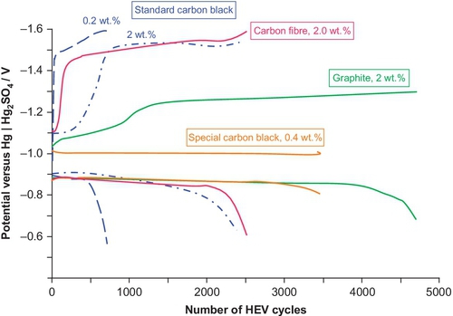
This approach can lead to a remarkable improvement of the DCA and of the cycle life even under PSoC conditions (see “Depth of discharge and dynamic charge acceptance” section). But the influence of the carbon on lifetime depends on the concentration and the type of carbon used (see Figure 5.11).
The type and the amount of the carbon addition to the negative active mass must be well coordinated with the organic expander used; otherwise, water loss increases, and cold-cranking performance decreases.
5.4.2.2 Carbon on the grid side of the active mass (in place of the lead alloy)
In this case a porous carbon material acts as a current collector, which is impregnated with a slurry of lead oxides and then formed to sponge lead on the negative plate as normal. Because of the porous structure, the resultant negative plate has an enormous surface-area advantage over conventional lead–acid grid structures. This results in much-improved active material utilization and enhanced fast-recharge capability. The foam structure, which encapsulates the active mass, can also lead to a higher lifetime (Figure 5.12) in high-rate charge applications.
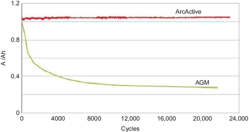
This approach is being developed by both Firefly International Energy (with Microcell™ composite foam) and ArcActive Ltd. (with reticulated vitreous carbon that has been activated by an electric arc).
5.4.2.3 Carbon on the outside of the active mass (adjacent to the electrolyte)
In comparison to supercapacitors, the power of LAB is relatively low and limited by the negative electrode. To increase the power capability of the LAB the lead negative electrode is combined with a supercapacitor carbon electrode in the UltraBattery® (Figure 5.13).
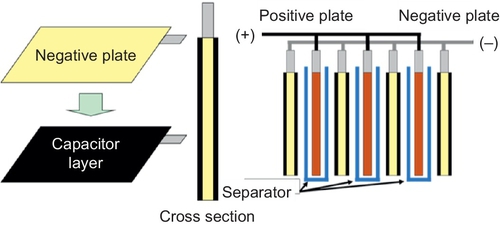
In this design the capacitor electrode and the negative VRLA battery plate work in parallel, that is, the total current of the combined negative plate consists of the capacitor current and the VRLA negative-plate current. In this way the capacitor electrode can act as a buffer to share current with the lead plate and thus prevent it from being discharged and charged at high rates. With this strategy in place high cycle numbers (four times higher than for a conventional VRLA battery) can be achieved in high-rate PSoC operation (Furukawa, 2014).
5.5 Advantages and disadvantages of LABs in HEV applications: general
There are a variety of applications of batteries in automobiles. In addition to the SLI functions, traction batteries could be used for several purposes in cars with different degrees of electrification, as shown in Table 5.1.
Table 5.1
Functions of different hybrid battery cars with their electrical functions, CO2 emission reduction and cost
| Micro HEV start/stop and regenerative braking | Mild HEV + launch assist | Full HEV + power assist and limited e-drive | Plug-in HEV + extended e-drive | |
| Preferred battery | EFB, AGM | Li-ion, LAB + Li-ion | Ni-MH, Li-ion | Li-ion |
| System voltage (V) | 14(− 48) | 48–150 | > 200 | > 200 |
| Battery power (kW) | 2–10 | 7–20 | > 20 | > 20 |
| Usable battery energy (additional to SLI) (kWh) | 0–0.25 | 0.25–1 | 0.7–2.5 | 4–10 |
| Launch assist (kW) | 0 | < 15 | > 15 | > 60 |
| e-Drive range (km) | 0 | 0 | ~ 2 | ~ 30 |
| OEM on-cost | €150–700a | €1600–3000a | €3000–5000a | €6000–10,000a |
| CO2 benefit (%) | 4–7 | 8–12 | 15–20 | 20 + |
| Cost (€) to achieve each 1% reduction in CO2 emissions | 35–100 | 200–250 | 200–250 | 300–500 |

Based on Cooper (2014), Budde-Meiwes et al. (2013), and Frost and Sullivan (2013).
a Estimate.
With increasing function levels of xHEVs from the left to the right side of Table 5.1, the demand imposed on the battery increases. This is mainly related to the deeper discharges that are necessary with increased electric powertrain functionality and the higher charge acceptance required for regenerative braking.
Both absolute cycling throughput and the high-rate PSoC cycling demand (Section 5.2.3.3, Figure 5.8) have so far prevented widespread use of conventional LABs in mild, full, and plug-in hybrid vehicle applications. To date, only nickel–metal-hydride and lithium-ion batteries have been used in these applications.
5.5.1 Micro-HEVs (14 V systems)
To date, the microhybrid application, where the throughput and power demands are modest, is dominated by LABs, either EFB or AGM. It has been demonstrated that both technologies can support shallow cycling throughput exceeding 500 times nominal capacity. Even during more substantial PSoC cycling, for example, at 17.5% DoD (prEN 50342-6 levels M2/M3), more than 250 times nominal capacity are achieved by several EFB and all automotive AGM products. The deeper cycling requirements in the latter case would already exceed the demand of the typically shallow, microhybrid duty cycle, which gives rise to weight-optimized EFB solutions found in many passenger cars, particularly small cars or vehicles with manual transmission (SBA S0101:2006, prEN 50342-6 level M1).
The DCA of all LABs strongly depends on their short-term cycling history. Figure 5.14 illustrates a run-in experiment that simulates, without experimental acceleration, microhybrid battery operation under a set of difficult or worst-case conditions: engine after-run and key offloads discharge the battery before and during many, also long, parking events, idle-off loads and the like. Under these conditions, the DCA of typical flooded, enhanced flooded, and AGM batteries settles around 0.2 A/Ah. This is a run-in effect and should not be misinterpreted as aging: The battery can fulfill all power-supply system functions for years at this low DCA level. Actually the high initial DCA is an effect of the initial capacity test that was performed with the test samples; if this is omitted, DCA will be much closer to the run-in level right from the beginning of service. Some conventional flooded batteries show significantly lower DCA below 0.1 A/Ah (for example, poor flooded curve in Figure 5.14), which would not consistently support the stop/start functionality in urban traffic. Consequently, such low-DCA batteries will not be allowed to carry the stop/start label defined in prEN50342-6. Conversely, several innovative additives to the NAM or the electrolyte have been demonstrated to keep the DCA of EFBs around or above 0.5 A/Ah (for example, see the EFG gen-2 curve in Figure 5.14), usually at somewhat elevated gassing and water consumption levels. It can be expected that by optimization of material compositions and perhaps alternator operating strategies, such high DCA levels can be achieved robustly without deteriorating battery service life in warm and hot climates. EFBs with high DCA improve real-world fuel economy, reduce the risk of car breakdowns due to undercharge and sulfation, and offer further lead-weight reduction opportunities. In theory, similar concepts can be applied to 12 V AGM batteries. However, demand from vehicle OEMs regarding DCA or weight optimization of AGM appears to be weak, as the market for automotive AGM batteries becomes progressively constricted to premium applications with substantially deeper cycling requirements beyond just microhybridization.

In most customer vehicles, DCA will be somewhat higher than the worst-case results illustrated in Figure 5.14. Nevertheless, the alternator in modern vehicles can supply 150–250 A during deceleration, which by far exceeds the DCA of any known LAB technology: Even at 1 A/Ah, the typical starter battery sizes between 50 and 80 Ah would realize only a third to half of the brake energy recuperation in an optimized 14 V power supply system (Figure 5.15). As lithium-ion batteries do not share the DCA weakness described above, they have been suggested as an alternative starter battery technology that would, in addition, provide a significant weight reduction. However, their market penetration is low up to now due to some technical issues (e.g., limitations of cold-cranking and cold-charging power, incompatibility with engine bay package locations owing to heat intolerance) and very significant on-cost. As a consequence, several car makers have already introduced or are developing dual storage solutions that combine the robust lead–acid base starter battery with a high-power storage device that provides consistently high DCA (Warm et al., 2014) and protects the LAB against excessive cyclic aging (Schindler et al., 2012). It appears that lithium iron-phosphate and lithium titanate batteries are the most promising cell types for these add-on solutions because they can operate robustly within the voltage window above the open circuit voltage (OCV) of LABs and below the maximum automotive system voltage around 15 V, that is, they avoid the need for a dc/dc converter between both storage devices. In the longer run, it is certainly possible that lithium-ion technology makes further progress toward a complete drop-in replacement of the lead–acid starter battery.

5.5.2 Mild-HEVs and 48 V systems
The power limitations of the 14 V alternators can be overcome by introducing a higher voltage level for generator and battery, for example, 7–12 kW on 48 V nominal system voltages, which would allow avoiding certain cost-intensive high-volt safety measures that would be required above 60 V. A 48 V system enables recuperation of more energy during typical drive cycles than would be consumed in electric ancillaries and hence is typically designed as a mild hybrid that consumes excess electricity in propulsion functions, sometimes in combination with aggressive engine downsizing (see Section 5.6.4). Actually, the older mild hybrid systems that typically operated in the 120–150 V range are tend to be replaced by either full hybrids or 48 V systems. In addition to their powertrain functionality, 48 V systems are expected to enable additional electric functions (e.g., chassis comfort) that would exceed the power capability of 14 V systems. As the on-cost associated with the introduction of a second voltage distribution in vehicles is substantial, most market introduction scenarios assume a business case combined of a reduction in CO2 emissions and new electric comfort functions in premium cars.
So far, all 48 V industrialization projects assume the use of high-power lithium-ion batteries or of supercapacitors where the focus is exclusively on high-power ancillaries. Recently, several experimental 48 V vehicles have been equipped with spiral-wound or prismatic AGM batteries that use innovative carbon additives in the NAM to enhance DCA. A string of 21 or 22 cells, that is, a battery nominal voltage of 42 or 44 V, fits into the 48 V system voltage specifications. Some examples are the LC Super Hybrid vehicle demonstration project funded by the UK government and Kia/Hyundai concept vehicles at Geneva and Paris motor shows in 2014. Because of higher battery weight, DCA run-in degradation, lower energetic charge/discharge efficiency, and inherent cycle life limitations, it is difficult for lead/carbon AGM batteries to outpace existing lithium-ion solutions technically. Nevertheless, several LAB developers believe they can offset these technical deficiencies by low material cost and applying mature automotive battery production processes, particularly in applications that are not primarily driven by CO2 saving requirements but by new electric functions. When it comes to robust delivery of power at very low and very high temperatures, the lead–acid chemistry has an inherent advantage over lithium-ion.
5.5.3 EV applications
For a few “light” pure electric transportation applications such as golf carts, airport passenger transportation vehicles, and the like, LABs (often VRLA) are used. In the future there may be a class of battery electric automobile, such as the neighborhood EV, for which the limited range and relatively short cycle life are sufficiently offset by the low first cost of a lead–acid design, but for all vehicles with a range between charges of over 100 miles or 160 km, lithium-ion batteries will be needed.
5.6 Potential future developments in LABs and HEVs
In addition to the continuous improvement of the technical parameters and cost reduction of LABs in recent years, there have been some important new developments.
5.6.1 The addition of carbon
The addition of certain types of carbon in a variety of configurations has been shown to provide a very significant improvement in the performance of LABs that are intended for use in the high-rate PSoC duty that is the characteristic of HEVs. Although the parent technology has a very long history, this special exploitation of carbon is relatively new, and it is likely that the optimization process will yield rewards for some time to come. See more about this topic in Section 5.4.2.
5.6.2 Bipolar batteries
Bipolar cell configurations are used especially for fuel cells but also sometimes in batteries that are intended to provide high voltage and high power. In the bipolar design the geometric electrode surface, and therefore the capacity, is limited by the cross-section of the bipolar stack. The current path and cell weight can be minimized, and the current density is very homogeneous across the electrode (Saakes et al., 2005). Although there have been many attempts to develop this design of battery, they have all failed commercially, mainly because of corrosion of the bipolar plate and as a result of insufficient cell sealing. The only non-lead electronically-conducting bipolar plate materials with high corrosion stability that have shown promise are vitreous carbon, fluoride-doped tin dioxide, titanium suboxides (Magneli phases), or lead-infiltrated ceramic material.
Despite the challenges of this system, several companies continue to seek the final breakthrough.
5.6.3 Grid design
The current distribution across a flat plate electrode is nonuniform, especially at high rates. The equipotential curves of a state-of-the-art electrode with a central lug (Figure 5.16) show that, due to high potential losses, the lower part of the electrode is hardly involved at all during high rate discharge.
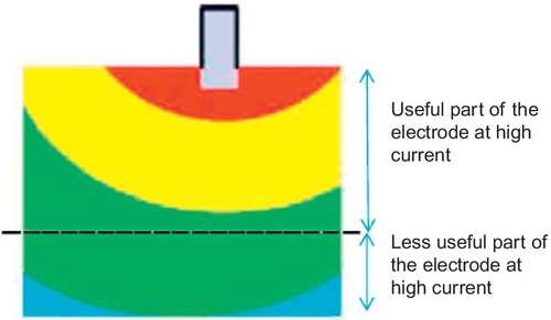
A consequence of this finding is that it is advisable to use shorter electrodes or to use two lugs (one at the top of the cell and one at the bottom) on each plate when high-current operation is required. The so-called Rholab battery (Figure 5.17), which incorporated the latter principle, was used successfully as a much cheaper alternative, to replace the original nickel–metal-hydride battery in a Honda Insight.

A twin-tab design is not simple to manufacture, but the importance of high power, particularly during charge events, dictates that development of a grid design to match the needs of HEV batteries is likely to continue.
5.6.4 Batteries for downsize and for boost
As shown in Table 5.1 mild HEVs, full HEVs, and plug-in hybrid electric vehicles (PHEVs) show in relation to micro-HEVs higher fuel savings/CO2 emission reductions, but at much higher specific costs ($/% CO2 saving).
One approach for having higher fuel savings at low specific costs is to reduce the size of the engine of conventional cars and making good the consequent loss of power by the addition of an enlarged turbocharger, electric supercharger, and a 48 V system (see Figure 5.18).
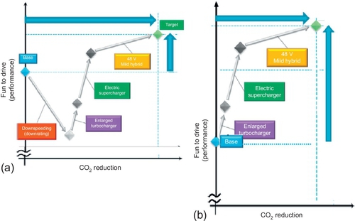
Using the same concept but without downsizing the engine is another approach to achieving higher car performances, but not to quite as high a fuel savings as the first approach.
The Advanced Lead–Acid Battery Consortium (ALABC) conducted two relevant projects:
![]() Downsize project: 2 L Ford Focus with a radically downsized (1.0 L) three-cylinder gasoline engine, enlarged turbocharger, electric supercharger, and a 220 F supercapacitor for energy storage.
Downsize project: 2 L Ford Focus with a radically downsized (1.0 L) three-cylinder gasoline engine, enlarged turbocharger, electric supercharger, and a 220 F supercapacitor for energy storage.
![]() Boost project: 1.4 L TSI Passat, without downsizing but with enlarged turbocharger, electric supercharger, and a 42 V/24 Ah Exide Orbital lead–carbon battery for energy storage.
Boost project: 1.4 L TSI Passat, without downsizing but with enlarged turbocharger, electric supercharger, and a 42 V/24 Ah Exide Orbital lead–carbon battery for energy storage.
Based on these projects first approximations for savings and costs by super hybrids have been done:
![]() CO2 emission reduction: 15–30%,
CO2 emission reduction: 15–30%,
![]() Specific OEM cost: €50–60/% CO2 emission reduction.
Specific OEM cost: €50–60/% CO2 emission reduction.
5.7 Market forecast
The principal market driver for sales of LABs is the inexorable growth in the number of cars worldwide (see Figure 5.19).

In the next few years, however, the conventional SLI battery will be replaced by advanced LABs for microhybrid cars. It is expected that by 2020, some 50% of all types of cars will be microhybrids, and the numbers of full HEVs will decrease (see Figure 5.20).

Therefore, an increase of LAB production will continue based on micro-HEVs with the advanced battery designs that have been described above as shown in Figure 5.21.

5.8 Sources of further information
Berndt, D., 2003. Maintenance Free Batteries. Research Studies Press, Baldock, Hertfordshire.
Broussely, M., Pistoia, G., 2007. Industrial Applications of Batteries—From Cars to Aerospace and Energy Storage. Elsevier, Amsterdam.
EUROBAT, ACEA, JAMA, KAMA, ILA, 2014. A review of battery technologies for automotive applications. http://www.eurobat.org/sites/default/files/rev_of_battery_executive_web_1.pdf (accessed 20.10.14.).
Garche, J., Dyer, C.K., Moseley, P.T., Ogumi, Z., Rand, D.A.J., Scrosati, B., 2009. Encyclopedia of Electrochemical Power Sources, vol. 4. Elsevier, Amsterdam.
Glaize, Ch., Genies, S., 2012. Lead and Nickel Electrochemical Batteries. ISTE and Wiley.
Rand, D.A.J., Moseley, P.T., Garche, J., Parker, C.D., 2004. Valve-Regulated Lead–Acid Batteries. Elsevier, Amsterdam.