Roofing materials for thermal performance and environmental integration of buildings
Abstract:
Roofs can represent 50–70% of the total enclosure loads for a building. The roof typically receives significant amounts of solar radiation and consequently represents both a concern for energy consumption as well as an opportunity for environmental expression. The roof is where the building meets the sky and therefore the design of the roofing system should consider not only the materials and construction characteristics but also the possibilities for environmental integration. This chapter presents issues and design strategies for the roof being an active participant in environmentally responsive architecture. The issues presented include: the construction and selection of materials for thermal performance and reuse or recycling, active solar collection, natural ventilation, and rainwater harvesting. An introduction is given to emerging roofing systems such as bio-composite materials and green roofs as well as fundamental performance issues such as sol-air temperature. Tables are included as references for thermal properties of common roof materials as well as solar absorptance properties of various roof weather protection layers.
19.1 A question of design
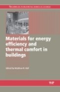
Architectural design involves the exploration and evaluation of alternative propositions in response to many questions, some tangible others less so. Unfortunately, seldom does it seem in contemporary architecture is the question asked: How should the building meet the sky? Arguably through this question architecture can best express a response to regional differences in site, climate, sun and culture. Historically the roof was the building’s hat worn to speak to these differences. The pitched, thatched roofs of hot humid locations such as in the islands of the Caribbean or South Pacific effectively shed rain while dissipating heat from solar radiation (Fig. 19.1). The steeply sloped roofs of Cape Cod houses in the Northeast US or of Northern Europe are designed to prevent the accumulation of snow and avoid large live loads on the building structure. Low slope roofs in hot arid regions such as Northern Africa, the Middle East, Mexico and the Southwest US are typically constructed of light colored, high mass materials such as adobe, compacted earth, or concrete to first reflect and then delay the impact of the sun from excessively hot days to cool nights. In these situations the construction of the roof tells a story about the regional conditions that the building responds to.
19.1 Thatched roof structures from the Caribbean and Pacific islands shed rain and dissipate solar radiation.
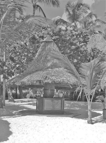
While the question of ‘How should the building meet the sky?’ is seldom asked, a few recent projects do demonstrate the role the roof can play toward effectively responding to local environmental conditions. The British Pavilion by Nicholas Grimshaw for Expo ’92 in Seville, Spain (Fig. 19.2a), is an elegant statement of building meeting the sky where a series of curving rooftop panels integrate photovoltaic cells to convert sunlight into electricity while also acting as a shading canopy. The Tjibaou Cultural Center by Renzo Piano (Fig. 19.2b), borrows from the thatched roofs of the indigenous Kanak people in New Caledonia as inspiration for a series of curving double-skin ‘cases’, where walls merge with the roof to rise on the landscape and respond to the prevailing winds for natural ventilation. Similarly the gentle wave-like curves of Thomas Herzog’s Hall 26 in Hannover, Germany (Fig.19.2c), admit daylight while compressing and accelerating the wind flowing over the building to induce a draught that draws warm stale air out of the building through carefully designed openings at the crest of the roof waveforms. These projects demonstrate the expressive role that the roof can play in environmentally responsive architecture.
19.2 Environmentally responsive roof solutions: (a) Nicholas Grimshaw’s British Pavilion (Humm & Toggweiler 1993: 45), (b) Renzo Piano’s Tjibaou Cultural Center (Buchanan 2000: 95), and (c) Thomas Herzog’s Hall 26 (Jones 1998: 171).
When considering energy consumption, with the exception of fenestration, for many buildings the roof is the most significant envelope component. The influence of the roof on heating and cooling loads may range from nearly negligible for narrow plan multi-story buildings, to well over 50% for large area single story buildings such as schools or warehouses. The Oak Ridge National Laboratory reports that the roof can comprise 50–75% of a building’s total envelope loads (ORNL 2003). As the influence of the roof increases, care should be taken to properly specify the construction of the roof assembly and to explore opportunities for the roof to actively participate as an environmentally responsive feature.
When specifying the design and construction of the roof, at least five issues should be considered:
19.2 Roof construction
19.2.1 Decking layers
Roofs are typically constructed of a structural system (beams or joists) either supporting or integral with a decking layer, an insulation layer and an exterior weather protection layer. For residential and light commercial frame construction, roof decks are typically wood planks, plywood, oriented strandboard (OSB), or cementitious wood fiber. These materials are usually lightweight and easily workable without heavy construction equipment. Wood-based roof decking is most appropriate for short-span installations of about 30.5 cm to 61 cm on center (12″ to 24″ between rafters) with relatively low structural load carrying requirements. Wood decking products typically have relatively low embodied energy when compared to steel or concrete, and are somewhat renewable, as many wood-based products can be re-grown in a relatively short period of time. Wood-based decking layers may add a small amount of resistance to heat flow but provide little thermal mass to the system. Thermal resistance values for plywood building boards range from 0.054 m2 K/W (0.31 ft2 F h/Btu) for 6.35 mm (0.25 inch) thick decks to 0.16 m2 K/W (0.93 ft2 F h/Btu) for 19 mm (0.75 inch) thickness; for vegetable fiber board about 0.165 m2 K/W (0.94 ft2 F h/Btu) for 9.5 mm (0.375 inch) shingle backer and 0.144 m2 K/W (0.82 ft2 F h/Btu) for 16 mm (0.625 inch) thick particle board. (ASHRAE 2005: table 4, ch. 25). While the wood decking does provide some resistance to heat flow, an additional insulation layer is typically required.
When considering the environmental impact from building waste and design for reuse, typically wood frame construction does not lend itself to recycling. This is because nails and screws are often difficult and time consuming to remove. Use of alternative attachment techniques such as glues and adhesives also do not support disassembly while demountable fastening systems such as nuts and bolting are time-intensive to install or remove and increase initial costs. Recently developed decking products such as bio-composites are more responsive to waste management concerns through the use of more sustainable materials such as wheat, straw and soy. Companies such as Composite Technology Park (CTP) have developed engineered mixtures of glass-fiber and natural fiber, typically including bamboo, coir and jute fibers that are renewable and bio-degradable (Composite Technology Park 2008). In addition to being more environmentally friendly and structurally superior to common wood roof decking components, these products are resistant to water, fungus, mold and rot. Environ bio-composites Inc. has a similar line of products for roof decks made from agricultural fiber, sunflower hulls, wheat straw and soy-based resin (Environ Bio-composites 2008). Products such as these have the two-fold benefit of higher renewable source content and when discarded to landfills they biodegrade much quicker than typical wood decks.
Roof decks for non-residential buildings typically support longer spans and carry greater structural loads for roof-top systems such as heating, ventilating and air-conditioning (HVAC), and for maintenance personnel and their heavy tools or equipment. To support these building systems, the roof deck is often reinforced or thickened by a few inches under these equipment. For example for poured concrete roof decks the concrete thickness is typically increased from about 10 cm (4 inches) to 15 cm (6 inches) or 20 cm (8 inches) directly under the HVAC systems. This additional mass helps absorb structural vibration while providing greater support.
Non-residential roof decks are usually made of pre-cast concrete, pre-stressed concrete or corrugated metal (galvanized steel or aluminum) or fiberglass supporting poured-in-place concrete or poured gypsum. Concrete decking adds thermal mass to the system but offers little resistance to heat flow. When thermal performance is a priority, lightweight insulating concrete (k = 0.11 to 0.78 W/m K) (0.8 to 5.4 Btu in/h ft2 °F) (ASHRAE 2005: table 4, ch. 25) can provide the benefits of thermal mass while being more resistant to conductive heat flow, although the structural performance and compressive strength may be lower. These concrete products have higher thermal resistance due to an aeration process that introduces very small air pockets into the concrete as it cures. The result is a lower density material with thermal conductivity as little as one-tenth or less of standard concrete, depending on the composition and density. Aerated concrete can be poured-in-place or pre-cast.
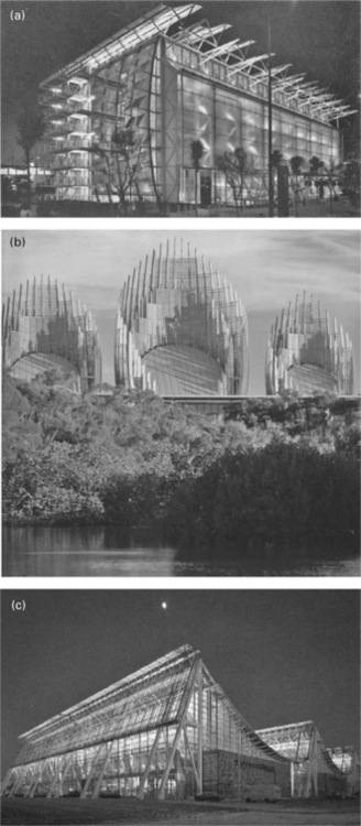
Because of the common use of metal reinforcement bars or steel mesh in non-residential roof decks, poured concrete systems typically do not lend themselves to removal and reuse. As a result when the building is demolished these roof decks are often broken up and hauled to the landfill. Due to the high embodied energy associated with both steel and concrete, alternative construction procedures for both assembly and disassembly should be considered. For this a more desirable roof construction strategy may be to use either solid or hollow-core precast concrete planks that can be interlocked and span several meters between primary structural members (Fig. 19.3). At the end of the building’s useful life, the roof finish can be removed and the planks detached and recycled. The hollow cores also present an opportunity for active air flow integration through the roof to remove solar heat gain before it penetrates to the occupied zones of the building.
One important consideration for the roof decking layer is whether to incorporate heavy construction with thermal mass to delay the effects of the sun and hot midday sol-air temperatures. For building types and climate zones with cooling-dominated operation, roof decks are often constructed of high mass materials such as concrete that delay the impact of the sun on the interior of the building. Typical high mass roof decks may contain as little as about 5–15 cm or more concrete, with corresponding thermal lags of from 1–4 h or more. This can delay the heat gain through the roof to later unoccupied hours thus reducing both energy consumption and cooling system sizing. Thermal capacitances for typical roof assemblies are given in table 18 of Chapter 30 of the 2005 ASHRAE Handbook – Fundamentals and range from 6800 J/m2 (0.6 Btu/ft2 °F) for sloped frame roofs to over 238000 J/m2 (21 Btu/ft2 °F) for concrete roof decks. While the most cost effective thickness of the roof thermal mass will depend on several factors related to building design, use, materials and climate, the optimum thickness should be determined through hourly energy modeling and life cycle cost assessment. Generally for buildings in temperate to hot climate zones, with longer cooling seasons, the higher cost of the mass roof decking materials will be economically justifiable.
19.2.2 Insulation layer
In addition to the roof deck, insulation is typically required to reduce heat transfer through the roof assembly. Insulation products such as fiberglass blanket and batt are common for residential and small commercial buildings, while rigid insulation boards of expanded or extruded polystyrene or cellular polyisocyanurate are more frequently used for non-residential construction. Generally rigid insulation provides greater resistance to heat flow than other insulation types for similar thicknesses. Also, some rigid insulation materials such as beaded polystyrene may have a small percentage of recycled content or can be broken up and re-used as loose-fill insulation. Thermal conductivity properties for typical roofing insulation types are shown in Table 19.1.
Table 19.1
Common types of roof insulation (ASHRAE 2005: Chapter 30, Table 4)
| Material | k-value W/(m K) | (Btu in/h ft2 °F) |
| Perlite | 0.04–0.06 | (0.27–0.42) |
| Fiber board (organic bonded) | 0.04–0.06 | (0.30–0.40) |
| Polyisocyanurate | 0.02–0.025 | (0.14–0.18) |
| Perlite/polyisocyanurate composite | * | |
| Perlite/polyisocyanurate/perlite composite | * | |
| Wood fiber/polyiscyanurate composite | * | |
| Cellular foam glass | 0.04 | (0.32) |
| Glass fiber board | 0.036 | (0.25) |
| Expanded polystyrene | 0.029–0.036 | (0.20–0.26) |
| Perlite/expanded polystyrene composite | * | |
| Wood fiber/expanded polystyrene composite | * |
*Note: Conductivity will depend on the composition and relative amount of each material.
In recent years alternative roofing insulation materials such as cellulose are gaining popularity in part due to their negligible pollution during manufacture and relatively low embodied energy content when compared to rigid boards and fiberglass blankets. Made from recycled newsprint and other paper sources, and typically installed as loose-fill, cellulose insulations offer R-values of between 0.6 and 0.7 m2 K/W (3.6–4.0 h ft2 °F/Btu in). Because loose-fill cellulose volumetrically settles at a fairly high rate to approximately 80% of the initial level, the Insulation Contractors Association of America recommends an additional 25% thickness. (CIMA 2008). While cellulose insulating materials can be environmentally friendly, their application should be balanced with concerns that they tend to absorb and hold moisture, which can degrade the thermal properties, their fibers and chemicals (i.e. from ink) can be a skin and eye irritant, and they can be highly combustible and therefore are often treated with a fire retardant chemical.
Minimum thermal insulation standards have been established by building codes for most building types and locations as discussed below. Installing the insulation above a thermal mass roof deck generally yields a higher performing thermal barrier. This location can also moderate deck temperatures which reduces thermal movement of the deck and the potential for underdeck condensation. Standards organizations such as the American Society of Heating, Refrigerating and Air-conditioning Engineers (ASHRAE) through ASHRAE Standard 90 – Energy Efficient Design of New Buildings Except Low-Rise Residential Buildings (ASHRAE 1989), allows for less insulation in the envelope when the insulation is placed outside of the thermal mass. According to the ASHRAE, ‘insulation can be placed above the membrane in a protected or inverted roof system. With this approach, the roof membrane is installed on the deck, where it functions as a waterproofing membrane and vapor retarder. Insulation can be placed above and below membranes to function both as the base and protector for the membrane,’ (ASHRAE 2005: 24.3) When placed above the membrane the insulation is usually protected by a ballast layer of gravel or pavers. This ballast layer can also help dissipate solar radiation on the roof as shown in Table 19.6.
In the US, based on the Model Energy Code guidelines (Model Energy Code 2000), the following minimum roof insulation R-values are suggested for various geographic locations for typical building usage.
• Alaska, Southern Canada (approx. 5500–14000 HDD65 °F)
• New England, Upper Great Plains, Great Lakes, Mountain States (approx. 4500–10000 HDD65 °F)
• Mid-Atlantic, Great Northwest, Lower Great Plains (approx. 3500–7500 HDD65 °F)
• West Coast, Southwest, Deep South (Approx. 500–3000 HDD65 °F)
• Gulf Coast, South Atlantic, Hawaii, Northern Mexico (approx. 0–2500 HDD65 °F)
In their book Sun, Wind and Light, Brown and DeKay divide North America into eight climatic zones for residential construction, each with recommended roof insulation thickness ranges. Recommended values range from as little as 150–350 mm (8–16 inches) for region R-1, hot arid zone of extreme southern California or Northern Mexico, to 400 mm (18 inches) for extreme Northern Alaska. For non-residential construction they divide the US into eleven climatic zones with corresponding recommended roof insulation thicknesses of from 100–150 mm (4–6 inches) for zone C1, extreme southern Florida (hot humid) to 450 mm (18 inches) in northern Alaska. (Brown & DeKay 2001). It should be noted that these recommendations are for thicknesses of batt insulation and if rigid insulation is used, as is common for non-residential construction, then the thickness could be correspondingly less as the R-values for rigid insulation are typically higher than for batt insulation. It should also be noted that these thickness are most economical given current purchased energy prices in the US. In Europe, which typically has higher energy costs, and as fuel prices escalate, more insulation may be justifiable.
For reasons of constructability and moisture control, many roof assemblies often include one or more air layers. For near still air conditions the thermal resistance of an air space will depend on the position (horizontal, vertical or sloped), the direction of heat flow (up or down), the mean temperature of the air in the cavity, the temperature difference across the space, and the depth. As given in table 3 in ch. 25 of the 2005 ASHRAE Handbook – Fundamentals, the thermal resistance of an air space may range from as little as 0.13 m2 K/W (0.73 ft2 °F h/Btu) to nearly 2.3 m2 K/w (13 ft2 °F h/ Btu). The addition of a low emissivity (upper surface) or radiantly reflective (lower surface) material to one of the air space surfaces can approximately double the R-value for the air space. Pre-manufactured aluminum-faced rigid insulation boards or blankets are available for this purpose. It should be noted that these radiant control materials (such as aluminum) are intended for applications across an air space. When not applied in correspondence with an air gap and when brought into direct contact with another material, the high conductivity of aluminum-based materials often negates the radiant benefits.
For residential, light commercial and other framed buildings such as some small schools, roofs are often assembled with an attic. When well sealed, the attic adds a large air space that can act as a thermal buffer between inside and out. When insulated and unvented the typical assumption for heating load calculations is that the temperature of the attic will be near the mean of the indoor and outdoor temperatures. Consequently for heat transfer (Q = (k∙ A∙ ΔT)/d) the presence of an attic air buffer can significantly reduce the temperature difference (ΔT) across the insulation layer during the heating season.
Unvented attics are most appropriate for locations with fairly severe heating needs and short cooling seasons. For locations and building types with relatively long overheating seasons, on the other hand, the sealed attic builds up heat and can be several degrees warmer than the ambient air temperature, depending on factors such as volume of the attic and absorptance of the exterior weatherproofing layer. This can significantly increase ΔT and the rate of heat gain to the occupied zones beneath the insulation layer. As a result, in locations such as the United States and Canada, attics are typically vented to remove heat and lower the interstitial air temperatures during overheated periods. For cold conditions it is typically assumed that the air temperature in a vented attic is equal to the outdoor air temperature. This two-season behavior suggests a seasonally adjustable venting system may be beneficial. During the underheating season the attic should be sealed by closing vent dampers. During the overheating periods it would be well vented by opening the dampers. This could be accomplished through thermostatically controlled vent dampers or power venting with temperature sensing and control. However, care must be taken not to draw moisture into the attic that could condense on cold surfaces.
Roof vents may be classified as static or power vents, ridge vents, turbine vents, soffit/cornice vents, gable vents, starter vents or cupola vents. A common rule of thumb for sizing the vent system is the 1/300 rule: one square foot of net free vent area (NFVA) for every 300 square feet of roof or attic area (equivalent to ~ 0.09 m2 per 27 m2). The net free vent area is the portion of the opening in the vent that actually ventilates and accounts for obstructions from bug screens and louvers. The NFVA may be as little as 40% or less of the overall size of the vent (Roofhelp 2008).
19.3 Thermal performance of roofing materials
19.3.1 Solar impact
For many building types and locations, an important question when designing and specifying the roof is, ‘How should I reduce or eliminate the impact of the solar radiation on the building’s cooling loads?’ This is because the sun is highest in altitude during the summer, and therefore the solar radiation on the roof is closest to perpendicular at times when the cooling loads are greatest (Fig. 19.4). When determining the heat gain (Watts) through a sunlit roof of thickness d, the temperature near the exterior surface is typically higher than the ambient air temperature and therefore the simple Q = (k∙ A∙ ΔT)/d) calculation, where ΔT is the temperature difference between inside and the ambient air, must be adjusted for radiant affects. This adjustment is often termed the sol-air temperature.
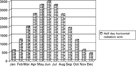
19.4 Half-day solar radiation intensities for 48° north latitude (source: ASHRAE 2005: table 8, ch. 27).
In their book Mechanical and Electrical Equipment for Buildings, Stein and Reynolds define the sol-air temperature as ‘the higher temperature of outdoor air just above a roof surface that is produced by solar radiation (and radiation exchange with the sky)’ (Stein & Reynolds 2000). The simplified formula for roofs in SI units is:
where: te = sol-air temperature (°C), to = outdoor (ambient) air dry bulb temperature (°C), α = absorptance of surface for solar radiation, I = total radiation incident on surface (W/m2) and ho = coefficient of heat transfer by longwave radiation and convection at the roof surface, usually assumed to be = 17.0 W/m2 °K. te can be 50 °C (120 °F) for light to 70 °C (160 °F) or higher for dark absorptive surfaces. This is a primary reason for the development and growing popularity of cool roof materials.
19.3.2 The exterior weather-protection layer
The exterior weather protection layer is most important for reducing the sol-air temperature. For residential construction with sloping roofs, fiberglass and asphalt composite shingles are very common. For low-slope (slopes less than 3/12 rise to run) non-residential construction, until recently asphalt or bitumen were often used as weather-protection layers. Asphalt-based materials are rather inexpensive and easy to install although, due to their dark color and high solar absorptance, they result in high sol-air temperatures with correspondingly high cooling load impact. In non-residential construction, light colored stone, gravel or thin concrete pavers are often added as a topping layer to further protect from maintenance traffic while reducing the solar absorptance. These topping layers add both cost and weight to the roof system.
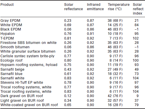
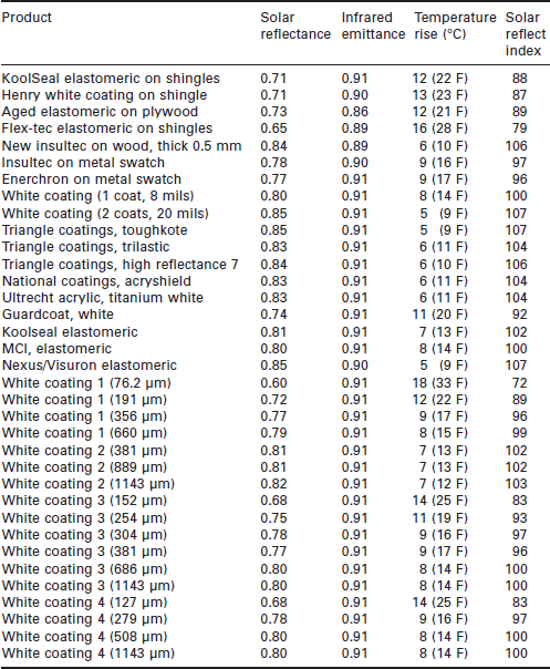
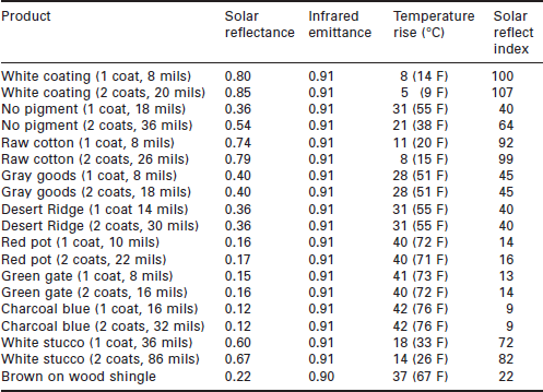
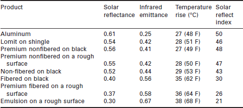
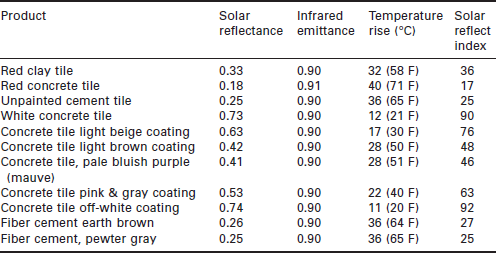
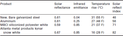
Cool roof materials such as light colored polyvinyl chloride (PVC) have been developed and applied to reduce solar absorptance and the sol-air temperature. Cool roof materials may be classified as elastomeric, polyurethane, or acrylic, all of which have been shown to retain solar reflectance over time. The US Department of Energy’s Lawrence Berkeley National Laboratories found that the reflectance of cool coatings decrease by only 20% over the life of these products and that most of the decrease occurs in the first year after application (USDOE 2008). However, these roofing systems should be cleaned regularly to remove dirt that can accumulate and increase solar absorptance. Many roof system suppliers also offer cool roof coatings that can be spray-coated over asphalt built-up or bitumen systems, increasing solar reflectance while reportedly extending the life of these roofs. Some of these applied coatings have aluminum content to increase solar reflectance. Care should be taken when specifying aluminum-based roof coatings as these may increase solar reflectance but their low emittance may offset this benefit. The solar properties for the most common of cool roof materials and coatings are shown in Tables 19.2 to 19.8.

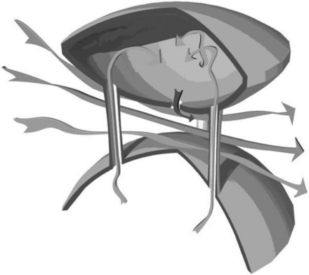
Cool roofs are often applied as a layered membrane system in sheets with nominal dimensioning. Although not the focus of this chapter, it should be noted that roofs typically experience negative pressure and uplift as winds flow over the building. To prevent tearing and detachment of these membranes, many building codes, particularly in high wind and coastal zones, require either mechanical attachment (screws), or fully adhering (gluing) the membrane to the insulation or decking layer. The mechanical attachments often introduce thermal bridges into the roof assembly increasing heat transfer. Ballast such as stones, gravel and pavers are also used to hold the membrane in place, but with added weight and cost to the roof assembly. New technologies such as the omni-directional roof vent, shown in Fig. 19.5, take advantage of aerodynamic principles such as the Bernoulli principle and Venturi effect to create a low-pressure field under the membrane that counteracts the uplifting force without the need for attachments, adhesion or ballasting.
19.4 Vegetated roofing systems
The temperature profiles shown in Fig. 19.6 suggest that, when solar loads and space cooling are important issues, an alternative to conventional (asphalt) or cool roof weather protection materials would be to introduce vegetation to the roof. Made popular through the roof garden designs of Frank Lloyd Wright and Le Corbusier, green roofs are now widely used in Europe and gaining popularity in North America. Green roofs can significantly lower the sol-air temperature due to the evapo-transpiration process that the planting medium undergoes. Evapo-transpiration is a complex process that depends on several factors such as type and density of the vegetation and ambient temperature and relative humidity. As shown in Fig. 19.6, due to this process temperatures for green roofs can be 16–22 °C (30–40 °F) lower than an asphalt or concrete roof.
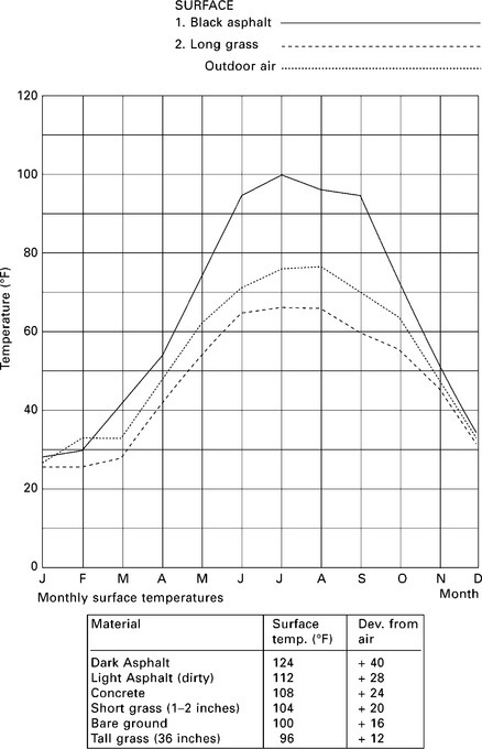
19.6 Horizontal surface temperatures for various sunlit materials. (source: Watson 1993)
Green roofs are typically classified in one of three categories. Intensive green roofs, also called high profile or roof gardens, have growing medium depths generally exceeding 150 mm (6 inches). Intensive green roofs can be 300 mm (12 inches) or more in depth and usually require irrigation and drainage for the planting materials. Extensive green roofs are also called low-profile roofs, eco-roofs or performance roofs and have growing medium depths of less than 150 mm (6 inches). Extensive green roofs usually require less maintenance than intensive systems and include small hardy plants and thick grasses. Due to their lighter weight and lower maintenance requirements extensive roofs are gaining popularity. In the United States, due to this increasing popularity, several roof system installers have developed a third modular classification with products that combine drainage, filtering, growing medium and vegetation layers, all installed in trays. These systems use modular block containers of anodized aluminum, polyethylene or recycled polystyrene and are easily transported, reducing installation time and effort. Suppliers such as GreenTech have developed pre-manufactured green roof modular trays of 100% recycled polyethylene (Fig. 19.7).
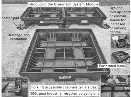
19.7 GreenTech Inc. polyethylene modular green roof trays. (source: GreenTech 2008)
In her dissertation titled ‘A decision-making framework for vegetated roofing system selection’, Elizabeth Grant suggests that the design of green roofs involves assessment of six performance mandates (Grant 2007). These include: storm water management, energy consumption, acoustics, structure, compliance and codes, and cost. Green roof systems are reported to both reduce and delay the volume of rainwater runoff. For buildings with large roof areas this can be a significant factor in selecting a green roof system. Grant cites that annual water retention for green roofs ranges from 40 to over 90% of incident rainfall depending on system type and depth of growing medium (FLL 1998). The green roof for the Ford Motor production facility in Dearborn, Michigan by William McDonough and Partners was installed in large part to offset the cost for on-site water retention and processing that would have been required if a conventional roof had been installed.
Green roofs are reported to reduce energy consumption in buildings through added thermal mass and by lowering sol-air temperatures. As previously introduced, the lower sol-air temperatures are primarily due to the evapo-transpiration of the plant media. For any given project the energy savings benefits will depend on a variety of factors including climate, building function and internal loads, and selection of the other roof components. The energy savings may range from only marginal when compared to buildings with concrete roof decks (thermal mass) and a highly reflective cool roof membrane in temperate or cool climates, to significant savings when compared to low mass roofs in predominantly cooling load-dominated buildings in moderate to hot climates. The application of green roofs should include a careful life cycle cost analysis using energy modelers such as EnergyPlus that include algorithms that model the evapo-transpiration process from green roofs. Simulation studies conducted for an institutional building for a temperate mid-Atlantic US location suggested that the energy savings from a green roof were small when compared to a typical high mass concrete roof with a cool roof membrane (Dhamne 2008).
As suggested by Grant, when considering a green roof, two additional performance mandates should be taken into account: impact on the structural system and cost. Green roofs are typically additive systems where a drainage layer, filter fabric, growing medium and plant material are added to the decking, insulation and weather-protection layers. Green roofs can add from 54 to 980 kg/m2 (11–200 psf) dead (self-weight) and live load (when saturated with water) to the roof system and $110–$220 per square meter ($10–$20 per square foot) in cost. However, when considering the green roof system, the decision to implement or not should be one based on a holistic view. The green roof is a system that can have both direct and indirect benefits. For example due to their relatively low surface temperatures, green roofs can reduce the urban heat island effect. This is part of the reason why cities such as Chicago, IL and Portland, OR have adopted incentive programs to encourage the installation of green roof systems. In addition to reducing rainwater runoff, the green roof for the Ford plant in Dearborn, MI provided a habitat for nesting birds in the region. Although difficult to quantify, these benefits should be considered as part of the decision-making process.
19.5 Solar integrated roofing systems
The question of how the building meets the sky might suggest opportunities for active solar collection to meet either electrical or thermal needs in the building. Depending on latitude, the roof typically has greater year-round solar collection potential per square meter than vertical walls. As a general rule-of-thumb for year-round collection, the tilt angle of the roof from the horizontal should be approximately equal to the altitude angle of the sun for noon on December 21, for the location in question. For greater heating season collection, the angle should be the altitude + 15° (more vertical) and for cooling season collection altitude – 15°. These angles are general for early design development and should be refined through a more rigorous analysis to determine the optimum tilt angle. Tools for early design analysis and cost versus savings assessment are available at the US National Renewable Energy Labs website (PVWatts 2008).
As previously shown, the British Pavilion for Expo ’92 is an expressive example of photovoltaic panels being considered as part of the roof system. For electrical production, photovoltaic manufacturers such as UniSolar Inc. have integrated their products directly into roofing materials (Fig. 19.8). The PVL-68, PVL-124 and PVL-136 flexible PV panels are 394 mm (15.5 inches) wide which can fit neatly between seams of standing-seam galvalum metal roofs (Uni-Solar 2008). Similarly UniSolar and HelioVolt Inc. in cooperation with roofing suppliers such as Acrylife Inc. are exploring the integration of photovoltaic panels directly into membrane roof systems during the manufacturing process. This has the potential to reduce the cost and installation time of the PV-integrated roof system while increasing life and durability. For the residential market, suppliers such as OkSolar (OkSolar 2008) have roof shingles with integrated PV that are easily applied to wood frame construction. While the above products typically use thin-film PV cells that have lower efficiencies when compared to crystalline or poly-crystalline technologies, recently developed thin-film PV products are quickly closing the gap for efficiency, making these systems more economically feasible. Also when designing a PV-integrated roof, care should be taken to simultaneously consider collector size and inverter capacity, as invertors are available in incremental sizes that should be matched with the collector. While the economic benefits of PV-integrated roofs vary from location to location and will depend on factors such as electrical demand and the local utility rate structure, with increasing manufacturing efficiencies and economies of scale, these products are likely to continue to gain popularity.
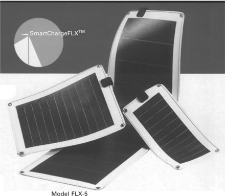
19.8 UniSolar Inc. PV integrated roof system. (source: Uni-Solar 2008)
For locations where incident solar radiation may be effectively harnessed, integrated thermal solar roof systems should be considered for both residential and non-residential buildings. Systems such as the rooftop air collector for an apartment block in Gothenburg Sweden by Christer Nordstrom, or the Orange Mode (OM) Solar roof, have been applied in Japan and Europe and are now being used in the United States for homes, schools and light commercial buildings. These systems act as a double envelope with a ventilated cavity between the solar collecting exterior layer and the insulating inner layer. (Fig. 19.9) (OM Solar 2001). Air flowing through the ventilated cavity absorbs heat which can be collected at the roof ridge and used for either space heating or transferred through a heat exchanger for pre-heating domestic hot water. In addition, the ventilated cavity can be used to collect and remove roof solar gains during overheated periods, thus reducing cooling loads. Solar integrated roof systems such as this can be economically viable when compared to additive thermal solar systems but attention should be given to construction quality as air leaks can degrade the benefits of the system. Also sensing and control for backflow prevention may be needed to prevent condensation inside the cavity. Studies of a full scale assembly on the campus of Virginia Tech (temperate climate zone) showed that over 60% of the annual space heating needs could be met with this system as the roof of a typical residential building (Xu 2004). SolarWall Inc. indicates that annual energy savings from a similar wall integrated system may range from 681392 KJ/m2 yr to 2,725,567 KJ/m2 yr in the continental US (Fig.19.10) (SolarWall 2008).
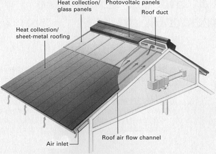
19.9 Schematic view of OM Solar thermal solar integrated roof system. (source: OM Solar 2001)
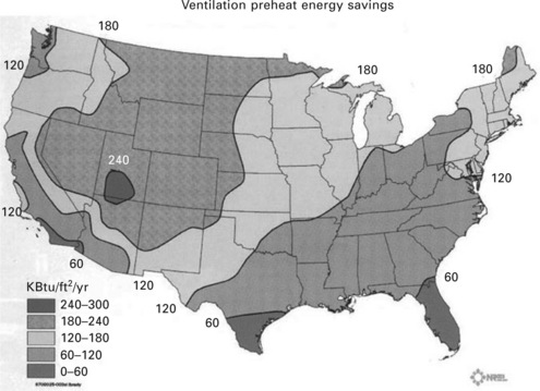
19.10 Estimated annual energy savings from the integration of a SolarWall enclosure system. (source: SolarWall 2008)
19.6 Natural ventilation
As introduced in Chapter 3 natural ventilation is a design strategy that can both reduce energy consumption and provide occupants with a positive psycho-physical connection between inside and out. When designing buildings for natural ventilation, the design of the roof can play a significant role in the ventilation strategy. Bernoulli’s principle indicates that as wind speed increases, pressure will decrease. Because of this, as wind flows over a building, it typically accelerates producing a low pressure uplifting force. This is why roofs often fail during high wind events such as hurricanes. This condition may be enhanced by moderately sloping the roof while smoothly compressing and accelerating the airflow on the windward surface of the roof and near the ridge. Utilization of the Bernoulli principle through the design of the roof can lead to solutions that intentionally create low pressure conditions to draw stale air out of the building. By analyzing wind speed and direction, and orienting the roof slope into the prevailing winds during periods when natural ventilation is appropriate, properly located roof openings can draw air out of the building. Figure 19.11 shows a proposed design of a middle school for Blacksburg, VA where wind tunnel studies indicated that the sloping roof could serve the natural ventilation strategy. In this building wind is compressed and accelerated over the moderately sloped roof creating a low pressure zone at the top of the corridor/atrium (Henderson 1999). This low pressure draws outdoor air through the adjacent classrooms and out of the building. Similarly Thomas Herzog’s Hall 26 was designed with a wave-form roof that compresses and accelerates the wind flowing over the building to create a low pressure region that draws air out of openings near the ridge of the roof. In both designs the roofs speak to their role in the natural ventilation system.
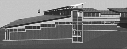
19.11 Image of a proposed naturally ventilated middle school for Blacksburg, VA. (source: Henderson 1999)
A special case of Bernoulli’s principle is shown in Fig. 19.11 where air is smoothly compressed through an opening with increased air speed and lower pressure. Termed the Venturi effect, this condition can be taken advantage of for the design of roofs for natural ventilation. The image in Fig. 19.11 is for the proposed design of a middle school that includes a roof section with an upper inverted aerofoil element supported above a convex lower element. As the prevailing winds smoothly compress through this roof element, low pressure is created. By coupling this low pressure to the building’s interior, outward airflow will be induced. Similar roof designs are employed in the Ionica building in Cambridge UK by RH Partnership as shown in Fig. 19.12(a) (Jones 1998: 80) and the RWE Ag building by Overdick and Partners in Essen, Germany (Fig. 19.12(b)) to achieve natural ventilation (Jones 1998: 217). In the Ionica building, inverted pyramids are raised above the top of the central atrium to create the low pressure condition and draw air up and out of the building. In the RWE building, an inverted aerofoil disk is lifted above the top floor to compress and accelerate the wind to induce upward air flow out of the central ventilation shaft of the building. In all of these buildings the roof not only plays an important role in the natural ventilation strategy but becomes a visual expression of environmental response.
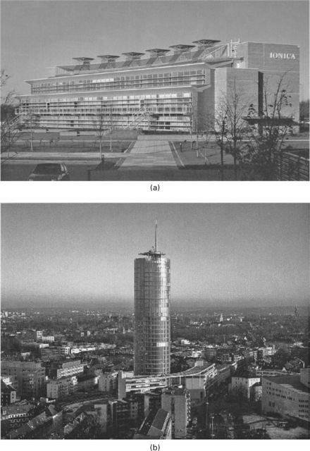
19.12 (a) Ionica Building (Jones 1998: 80) and (b) RWE Ag Building (Jones 1998: 217) utilizing roof elements to create a low pressure region to draw stale air out of each building.
19.7 Rainwater harvesting
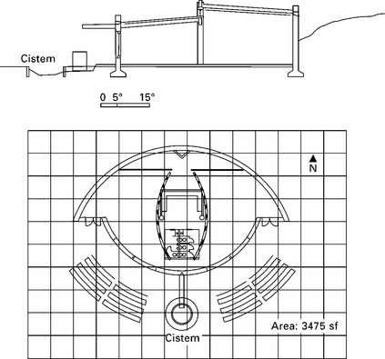
In addition to solar control and active collection, and natural ventilation, the roof has at least one other opportunity for environmental expression. For many regions of the world, including an increasing area of the United States, consumption and depletion of fresh water has become a serious environmental concern. As a result, programs such as the US Green Building Council’s Leadership in Energy and Environmental Design (LEED) (USGBC 2008) provide credits for architectural design strategies such as rainwater harvesting that aim to reduce off-site water consumption. For these systems the roof is the primary building enclosure element for collecting and possibly filtering, in the case of a green roof, the incidental rainfall. The design procedure for rainwater harvesting includes: basic planning (defining the roles between building and water use), estimating need (rates of consumption), estimating collection potential, and system detailing. The steps are summarized in depth in Stein & Reynolds 2000: ch. 9) and will not be repeated here. Average annual and monthly rainfall rates for estimating collection can be found through use of tools such as the Climate Consultant software available at http://www.aud.ucal.edu/energy-design-tools. One note should be made for applying the procedures for estimating rainwater collection: the roof area to be used is the projected horizontal area. For flat roofs this will be the actual roof area, but for sloping roofs the projected area will be less than the actual roof area.
Figure 19.13 shows a design for a small two-room environmental learning center to be located in Southwest Virginia, US. In this design the roof and rainwater collection cistern act together to provide students with an opportunity to observe and celebrate the rain and its collection. In this way the roof participates in the learning experience while expressing its environmentally responsive role within the building’s design.
19.8 The role of roofs in building rating systems
During the past several years building rating systems such as BREEAM and BEPAC have been developed and adopted to promote sustainability and environmental design. As an adaptation of these systems to the US building market, the US Green Building Council has developed and promoted the Leadership in Energy & Environmental Design (LEED) system to define and measure ‘green buildings’. The LEED system has four certification levels, Certified, Silver, Gold and Platinum, as an indicator for the level of environmental responsiveness. While the LEED rating system addresses a very wide range of design issues ranging from the site to stormwater management, and commissioning and construction management, it should be recognized that the roof can play a significant role in achieving a desirable rating.
In the LEED rating system the roof can contribute to several points toward the 69 maximum rating. For example, as previously shown, a vegetated roof can reduce rainwater runoff resulting in credit for stormwater management. Due to evapo-transpiration and the lower sol-air temperatures of vegetated roofs, credit can be taken for landscaping and exterior design to reduce heat islands. The use of the roof as a rainwater harvesting system can contribute to water use reduction, while the integration of active solar or photovoltaic sub-systems might be applied to minimum energy performance, renewable energy, and innovation in design credits. Through the integration of skylights, clearstory windows or a glass-covered atrium, the roof can be an aperture for daylight and views while providing a positive biophilia connection between inside and out. It should be recognized that the roof plays an important role in achieving LEED rating.
19.9 Conclusions
Choices for construction technique and materials play an important role in the performance of roof systems. The design of the roof should consider construction approaches such as hollow-core concrete planks that allow for both assembly and disassembly, and re-use, while roofing materials such as bio-composites can reduce the volume of building-related waste. Often the roof is the most important building enclosure component when considering energy consumption and solar control. The solar impact on the roof is often very significant as the air temperature near a dark colored sunlit roof can be several degrees higher than the ambient air. Light reflecting ‘cool’ roof materials are gaining popularity because of their lower sol-air temperatures when compared to conventional dark asphalt or bitumen roofs. In part for their lower surface temperatures due to evapo-transpiration, vegetated green roofs are also gaining popularity as an energy conservation system. Green roofs can also be applied as a rainwater management strategy while offering the added benefit of reducing the heat island effect in urban applications. Because of these and other potential benefits, the roof can account for several points in building rating systems such as LEED.
Systems integration should also be a part of the design strategy as active solar and photovoltaics can often be cost effectively merged with the roof system, particularly when using new roofing products that combine roof sub-systems with these environmental components. When properly oriented to prevailing breezes and sloped to create low pressure conditions, the roof can be an active participant in natural ventilation strategies. And, finally, the roof is typically the largest surface to receive rainfall and consequently should be considered as part of a rainwater harvesting system. We should view the roof as a design opportunity: an opportunity for expression of environmental responsiveness through solar collection and control, natural ventilation and/or rainwater harvesting. We should ask: How should the building meet the sky?
19.10 References
ASHRAEASHRAE/IESNA 90.1-1989 ASHRAE Standard: Energy Efficient Design of New Buildings Except Low-Rise Residential Buildings. Atlanta, GA: ASHRAE, 1989. [Table 8A].
ASHRAEASHRAE Handbook: Fundamentals. Atlanta, GA: The American Society of Heating, Refrigerating, and Air-Conditioning Engineers, Inc, 2005. [Table 4, pg. 25.5.].
Brown, G.Z., DeKay, M. Sun, Wind and Light – Architectural Design Strategies, Second edition, New York: John Wiley & Sons Inc.; 2001:214–217.
Buchanan, P. Renzo Piano Building Workshop – Complete works. London: Phaidon Press Limited; 2000.
CIMA. Cellulose Insulation Manufacturers Association. http://www.cellulose.org/CIMA/, 2008.
Composite Technology Park. http://www.compositestechnologypark.com/, 2008.
Dhamne, C., Energy Consumption Comparison for an Institutional Building located in Southwest Virginia with an “Extensive Green Roof System” College of Architecture and Urban Studies. Virginia Tech, Blacksburg, VA, 2008.
Environ Bio-composites. http://www.environbiocomposites.com/, 2008.
Forschungsgesellschaft Landschaftsentwickling Landschaftsbau e. V. (FLL), Bewertung von Dachbegrunung. Empfehlungen sur Bewertung in der Bauleitplanung, bei der Baugenehmigung und bei der Bauabnahme. FLL, Bonn, 1998.
Grant, E. A decision-making framework for vegetated roofing system selection, Doctoral dissertation, College of Architecture and Urban Studies. Blacksburg, VA: Virginia Tech; 2007.
GreenTech. http://www.greentechitm.com/systems/roof.asp, 2008
Henderson, James. Architecture for the imagination: a study of an elementary education environment, Graduate Thesis, College of Architecture and Urban Studies. Blacksburg, VA: Virginia Tech; 1999.
Humm, O., Toggweiler, P.Photovoltaics in Architecture. Berlin: Birkhauser Verlag, 1993.
Jones, D.L.Architecture and the Environment – Bioclimatic Building Design. Woodstock, NY: The Overlook Press, 1998.
, Model Energy CodeThe International Energy Conservation Code 2000. The International Code Council, 2000.
Ridge National Laboratory, Oak. R30/30 Roofing systems. http://www.ornl.gov/sci/roofs+walls/research/R30.htm, 2003. [5 Nov. 2003.].
OkSolar. OkSolar Inc. Photovoltaic integrated roof shingles. http://www.oksolar.com/roof/, 2008.
Solar, O.M.The Orange Mode. Sausalito, CA: The OM Solar Association Inc., 2001.
PVWatts. National Renewable Energy Laboratory Photovoltaic Calculator. http://rredc.nrel.gov/solar/codes_algs/PVWATTS/, 2008.
Roofhelp.com. http://www.roofhelp.com/ventilation2.htm, 2008
SolarWall. SolarWall Inc. – Solar integrated wall systems. http://solarwall.com/en/home.php, 2008.
Stein, B., Reynolds, J.S. Mechanical and Electrical Equipment for Buildings, 9th edn, New York: John Wiley & Sons Inc; 2000:135–136.
Uni-Solar. United Solar Ovonic Inc. Photovoltaic Integrated roof membranes. http://www.uni-solar.com/, 2008.
US Department of Energy, Lawrence Berkeley Laboratories. http://eetd.lbl.gov/coolroof/coating.htm, 2008
USGBC. US Green Building Council – Leadership in Energy and environmental Design. http://www.usgbc.org/DisplayPage.aspx?CMSPageID=222, 2008.
Watson, D. The Energy Design Handbook. Washington, DC: The American Institute of Architects, 1993; 38.
Xu, Z.Experimental study to determine the energy efficiency of an integrated solar thermal roof system, Master of Science Thesis, College of Architecture and Urban Studies. Blacksburg, VA: Virginia Tech, 2004.