Reflective materials and radiant barriers for insulation in buildings
Abstract:
Reflective insulations and radiant barriers are products used to reduce radiative transport across air spaces. The physical basis for these products, methods of testing, and the standards for reflective-type products are discussed in this chapter. Selected references to the existing literature are included.
12.1 Background and definitions
Thermal insulations used in buildings use the low thermal conductivity of gases to reduce heat flow. Mineral fiber, cellulosic, and open-cell plastic insulations use air as the low thermal conductivity component. The purpose of the fibrous or cellular material is to prevent free convection and reduce radiation. Cellular plastic insulation containing low thermal conductivity gases can provide thermal resistance greater than the air products as long as the gas remains in the cells. High thermal performance insulations based on evacuated powders or fibers or insulations with small diameter fibers or particles provide very high thermal resistance by reducing gas-phase conduction. Reflective insulations and radiant barriers are a class of materials that also rely on the low thermal conductivity of air for their performance. The thermal resistance of a reflective system is always less than the thermal resistance of an air space without convection or radiation since reduced pressure or nano-scale particles are not involved.
Reflective insulations and radiant barriers are materials used to reduce the transport of energy across air spaces in a building envelope. Both types of materials include surfaces with low emittance and high reflectance in the thermal spectrum (2–50 μm), i.e. near infra red (NIR) to mid infra red (MIR). These surfaces significantly reduce radiation across adjacent air spaces. Reflective insulation systems are characterized by having enclosed air spaces adjacent to low-emittance surface(s) while radiant barrier systems are associated with large ventilated or unventilated air spaces. Reflective insulation systems generally include air spaces up to about 0.25 m in the direction of heat flow. Radiant barriers systems generally have air spaces larger than 0.5 m.
Reflective insulation materials consist of one or more aluminum foils or metallized aluminum films bound to substrates (core material) primarily for mechanical support. The supporting materials include paper-type materials, plastics, or wood. In some cases the supporting material has a thermal resistance because of its thickness. Plastic bubble products or fiberglass batt material, for example, are used as core material. The thickness of the core material is generally in the range 3–25 mm. The thermal resistance of the core material is usually a small part of the overall resistance of the reflective air space. The thermal resistance is the result of reduced radiative transport across the enclosed air space and limited free convection. Reflective insulation systems have thermal resistances or R-values that can be measured and calculated. The thermal resistance of a reflective air space depends on orientation since there is a convective component of heat flow across the air space. Reflective insulations are commonly labeled with R-values for heat flow up, horizontal, and down.
Radiant barrier materials are most commonly single sheet materials consisting of aluminum foil or film bonded to reinforced plastic or paper or in some cases wood sheathing. A well-established North American product consists of foil bonded to oriented strand board for use as roof sheathing. Radiant barrier systems that consist of both a low-emittance surface facing a large air space with one or more enclosed reflective air spaces are also in use. These systems provide reduced radiative transport across the air space (radiant barrier) and thermal resistance associated with the reflective air spaces. Radiant barrier systems are evaluated in terms of reduced heat flow across the bounding air space rather than R-value. The performance of a radiant barrier system depends on the heat flow direction. This means that winter and summer performance for attic or roof mounted radiant barriers will be different. The performance of attic radiant barriers can be estimated for a given geographical location using computer modeling such as that described in ASTM C 1340. The modeling provides annual load reductions based on local weather data.
Both reflective insulation systems and radiant barrier systems can be achieved with liquid coatings having emittances in the range 0.20 to 0.30. At the present time, however, liquid coatings with emittances as low as aluminum foil or film are not available. The energy savings potential of liquid radiant barrier systems, therefore, is lower that that of the foil or metallized film products.
Aluminum has been the material of choice for reflective products because of its low emittance and relatively low cost. The emittance of aluminum foil products is in the range 0.03 to 0.05 on a scale of 0 to 1. Aluminum film products have slightly higher emittances because the deposited metallic surface must be protected from the surrounding atmosphere. The results of thin coatings to protect the metallized surface are emittances in the range 0.04 to 0.08. Long-term performance of a reflective system requires maintenance of low emittance. Contamination by dust or other debris or water damage increases the emittance and reduces savings. Cook et al. [1] have measured the effect of dust on emittance by distributing measured amounts of fine dust on a foil surface and measuring the resulting emittance using ASTM C 1371. The emittance increases from 0.03 to about 0.85 as the weight per unit area of dust was increased from 0 to 8 mg/cm2. Many of the common building materials have emittances in the range 0.8 to 0.9.
The heat flux, Q/A (W/m2), from a warm surface to a cool surface is described by a heat transfer coefficient for conduction and convection, hc (W/m2 K), and a radiation term, Ehr, as shown by Eq. 12.1,
where ΔT is the difference in temperature between the surfaces. The term hc includes conduction and convection while hr accounts for the radiative transfer. Equations and data for hc and hr will be discussed in following sections. The E in Eq. 12.1 is the effective emittance for the air space. E depends on the emittances of the surfaces bounding the enclosed air space. Reflective insulations and radiant barriers are produced with surfaces that result in E near zero. Equation 12.1 can be used to describe the heat flux to or from a surface to adjacent air if E is taken to be the emittance of the surface. Reflective insulation systems have R-values that depend on orientation, bounding temperatures, and the physical design of the system. Radiant barrier system performance is commonly stated in terms of heat flow or heat flux reduction. Heat flow is the product of heat flux and area. The commonly used units for these quantities are given in Table 12.1.

12.2 Applications and assemblies
The thermal performance of a reflective insulation system depends on heat flow direction, temperature difference across the air space, the average temperature, and the thermal emittances of the surfaces bounding the air space. The dependence of RSI on the distance across the air space is illustrated in Fig. 12.1 for three directions of heat flow.
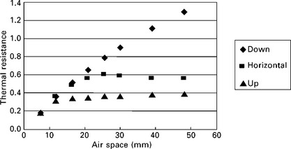
The thermal resistance for heat flow upward or horizontal maximizes at about 25 mm while the thermal resistance for downward heat flow increases with the distance across the air space. The downward heat flow is affected by stratification of the air with low-density air being at the top of the space. R-values for commercial products are usually less than R-values calculated for large parallel planes partly because of radiation absorbed by framing or supports (multi-dimensional effects).
A reflective insulation installed in a space of fixed dimensions can consist of one air space or multiple air spaces. Subdivision of a given space into two or more smaller air spaces will increase the overall thermal resistance by reducing both the radiative and the convective components of heat transfer. The convective component has a strong dependence on the temperature difference across the air space. Dividing a space into two regions, for example, will reduce the temperature drop across each space by a factor of about two with a corresponding reduction in convection. Table 12.2 contains calculated values for the thermal resistance of reflective air spaces at mean temperature 25 °C bounded by large parallel planes that illustrate the effect of air space dimensions and temperature difference on the thermal resistance.
Table 12.2
Calculated thermal resistances for selected reflective air spacesa Thermal Resistance (m2 K/W)
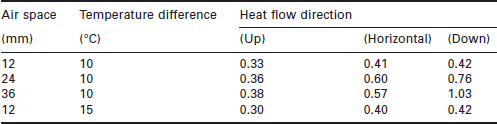
aTmean = 25 °C, emittances 0.9 and 0.03
The installation of a single layer reflective insulation material in the middle of a wall cavity or between floor joists to produce two enclosed air spaces is a very common application. Table 12.3 contains calculated thermal resistances for a fixed space divided into small regions. The results are based on large, parallel thin reflective membranes installed in a 50 mm wide space. The heat flow direction is horizontal and membrane thickness is neglected for the thermal resistances in Table 12.3.
Table 12.3
Effect of dividing a fixed space to produce multiple air spacesa

aTotal space 50 mm, bonding temperatures 15 °C and 25 °C
bLow emittance side 0.03 with high emittance side 0.9
cBoth sides of air space with emittance 0.03
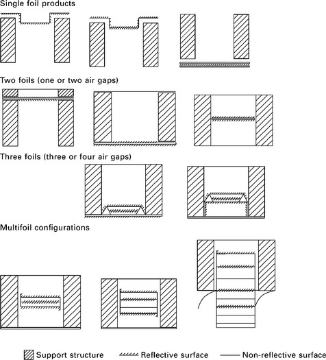
The cost associated with producing two low emittance surfaces for each air space often rules out this type of design since the added thermal performance shown in Table 12.3 is modest. Commercial products have existed with up to nine enclosed air spaces in series when a high R-value system is required. Figure 12.2 shows examples of assemblies that have been used for wood-frame or metal-frame structures. The core material for the reflective material can be either a single-sheet material, foam, or plastic bubble structure.
12.3 Basis for thermal performance
The performance of reflective insulations and radiant barriers is based on a reduction in heat transfer by radiation between hot and cold surfaces. The radiative flux Q/A (W/m2) from a surface at an absolute temperature, T, with emittance ε, is readily calculated from the Stefan–Boltzmann equation where σ, the Stefan–Boltzmann constant, equals 5.67 × 10− 8 W/m2 · K4. The radiative flux is directly proportional to the emittance, a property that varies from 0 to 1. Reflective insulations and radiant barriers utilize materials with low emittance surfaces. Aluminum foils with emittances in the range 0.03 to 0.04 have been a popular choice. Metallized aluminum films with protective coatings have come into use in recent years.
The net radiative transfer between parallel surfaces depends on the temperatures of the surfaces, the emittances of the surfaces, and the orientation of the surfaces. If surface 1 is hot and surface 2 is cold, then the net radiative transfer (Q12) is given by Eq. 12.3 where the term F12 is the overall interchange factor.
The evaluation of F12 is discussed in detail in the heat transfer literature. In the case of reflective insulation systems the discussions are generally limited to radiative transfer between large parallel surfaces with emittances ε1 and ε2. In this case, the interchange factor is expressed by Eq. 12.4. The interchange factor in this case is commonly called the ‘effective emittance (E)’.
In building application, the temperature differences (T1 – T2) are relatively small with the result that the radiative heat flux can be approximated as follows.

The heat flux due to convection-convection is represented by hc with the resulting total heat flux being the sum of the two terms. The units for hc and hr are W/m2·K.
A combination of Eq. 12.6 with the definition of R-value gives an expression for the thermal resistance of the enclosed air space.
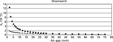
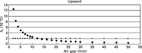
The term hc depends on the heat flow direction since it includes buoyancy driven free convection. The standard ISO 6946 contains equations for estimating hc for two important cases. Case 1 is an unvented space with length and width both more than 10 times the thickness, d. Figures 12.3, 12.4, and 12.5 show hc based on ISO 6946 as a function of the air gap, d, for the three major heat flow directions for the case ΔT across the air gap less than 5 K. Case 2 involves regions that don’t conform to the Case 1 dimensional requirements. There are many cases where a small temperature difference across the air gap is valid. If d is small, convection is absent and hc gives conductive transport at 10 °C. There are two curves in each of the three figures. The curves shown with diamonds represent a conduction dominated region. The curves shown as squares are for convection. R-values are calculated using the greater of the two values at a given gap thickness. The figures illustrate the onset of convection in a reflective air space. The curves for downward heat flow intersect at 60.7 mm. The curves for upward heat flow intersect at 12.8 mm while the curves for horizontal heat flow intersect at 20 mm. Convection is absent for air gap thicknesses less than the preceding values. Table 12.4 contains hc values for d greater than the intersection points.


ISO 6946 provides a method for calculating the radiative term when the air space does not satisfy the dimensional requirement stated earlier or the temperature difference across the air gap exceeds 5 K. Both of these conditions will reduce the thermal resistance of the air gap. An increase in the temperature difference results in increased convective transport while narrowing the width of the air space increases the radiative transport. Annex B in ISO 6946 contains the equations for making R-value calculations.
An extensive set of hot box measurements for reflective air spaces were made at the US National Bureau of Standards by Robinson and Powell in 1954 [2]. A second major set of hot box measurements were published by Desjarlais and Yarbrough in 1991 [3]. These data have been used to establish correlations for hc that include dependence of air gap temperature, air gap temperature difference, effective emittance, and heat flow direction. The graphical results in Fig. 12.1 were calculated using the correlations from the hot box tests. Equations for calculating hc that are based on the NBS hot box data are in the 1991 paper mentioned above.
12.4 Measurement of thermal performance
The thermal performance of reflective air spaces is generally determined using a hot box facility. Relatively large test specimens (2.5 × 3 m, for example) can be evaluated using a hot box facility. A flat test specimen is bounded on one side by a region containing a heater. The second side of the specimen is bounded by a temperature-controlled space. At steady state, the energy input to maintain a constant temperature on the hot side establishes the heat flux through the test specimen. The temperature difference between the hot and cold regions is the ΔT. Equation 12.7 can then be used to calculate the R-value which is the thermal resistance from the air space on the hot side of the specimen to the air space on the cold side of the specimen. Addition instrumentation provides the thermal resistance between the exterior or interior surfaces of the test specimen. Parallel-path heat flow calculations are used to isolate the thermal resistance of an enclosed cavity containing a reflective air space. Figures 12.6 and 12.7 contain photographs of a rotating hot box facility in operation at the Oak Ridge National Laboratory in Oak Ridge, TN, USA. The hot box is positioned for a horizontal heat flow measurement. Figure 12.7 shows the two parts of the hot box separated for insertion of a building element for testing. An apparatus of this type was used to generate the collection of thermal resistance values mentioned in previous sections.

12.6 A rotatable hot box positioned for horizontal heat flow (photo courtesy of the BTRIC, Oak Ridge National Laboratory, USA).
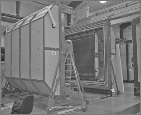
12.7 Hot box apparatus with sides parted to install test specimen (photo courtesy of the BTRIC, Oak Ridge National Laboratory, USA).
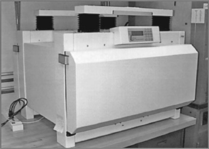
Relatively small test specimens that include a reflective air space can be evaluated using a heat-flow meter apparatus. The apparatus pictured in Fig. 12.8 can be used to test a 600 × 600 mm specimen up to about 150 mm thick with heat-flow up or down. This type of measurement, however, is usually limited to air gaps less than 50 mm. Smaller versions of the heat-flow meter apparatus have been mounted in a frame and rotated for horizontal heat flow measurements. Kanade and Yarbrough describe this type of measurement which is limited to small specimens that do not include framing or other types of obstructions [4].
Laboratory equipment of the type shown in Figures 12.6,12.7, and 12.8 is not used to evaluate radiant barriers. A large-scale facility that can be used to evaluate attic radiant barriers is shown in Fig. 12.9. The test specimen in Fig. 12.9 is a flat rectangular element. A small enclosed attic with pitched roof can be mounted in the frame and tested under a variety of conditions. The apparatus pictured in Fig. 12.9 operates as a hot box facility. The usefulness of this apparatus is enhanced by the fact that specimens with non-rectangular shapes can be tested (a specimen with triangular cross-section, for example).

12.9 Test element installed in the large scale climate simulator (photo courtesy of the BTRIC, Oak Ridge National Laboratory, USA).
The type of data that can be obtained from the apparatus in Fig. 12.9 is like that obtained with the conventional hot box. R-values for specific layers within the test element and overall heat transfer coefficients are determined using Eq. 12.7 with ΔT being the measured temperature difference across the element to be evaluated. The heat flux across the specimen is the same at all locations when steady-state conditions are achieved.
12.5 Codes and standards
Reflective insulation and radiant barrier products are subject to a variety of codes and standards around the world. Primary consideration is given to thermal performance evaluations including the measurement of the key physical property – thermal emittance. In addition, properties such as water vapor transmission, resistance to bleeding and delamination, resistance to fungal growth, combustion properties, and tear strength are examples of additional product requirements. Table 12.5 lists standards and specifications that are used in various parts of the world. The standards in Table 12.5 will guide the reader to test methods and computational methods for evaluating reflective insulations and radiant barriers.
Table 12.5
Standards and specifications related to reflective products
| Identification | Title |
| ISO 6946 | Building components and building elements – Thermal resistance and thermal transmittance – Calculation method (Versions of this document exist for individual countries) |
| CUAP | Common understanding of assessment procedure: products with radiant heat reflective component for use in thermal insulation systems of building envelopes |
| ASTM C 727 | Standard practice for installation and use of reflective insulation in building constructions |
| ASTM C 1224 | Standard specification for reflective insulation for building applications |
| ASTM C 1158 | Standard practice for installation and use of radiant barrier systems in building construction |
| ASTM C 1313 | Standard specification for sheet radiant barriers for building construction applications |
| ASTM C 1340 | Standard practice for evaluation of heat gain or loss through ceilings under attics containing radiant barriers by use of a computer program |
| NZS 4214:2006 | Methods of determining the total thermal resistance of parts of buildings |
| AS/NZS 4859 | Materials for the thermal insulation of buildings: General criteria and technical provisions |
| ICC-ES AC02 | Acceptance criteria for reflective foil insulation |
ISO International standards organization
ASTM American society for testing and materials
12.6 Sources of further information and advice
There is a vast literature associated with reflective insulations and radiant barriers. The literature includes handbook information and published research papers. A representative collection of available material is listed below.
ASHRAE Transactions 95 (Part 2) 1989 by W. P. Goss and R. G. Miller ‘Literature Review of Measurement and Predictions of Reflective Insulation System Performance, 1900–1989’.
Oak Ridge National Laboratory ORNL/TM-8891 by D. W. Yarbrough ‘Assessment of Reflective Insulations for Residential and Commercial Applications’.
Wilkes, G.B., Reflective InsulationHeat Insulation. New York: John Wiley and Sons, 1950. [Chapter 6].
Her Majesty’s Stationery Office, Nash, G.D., Comrie, J., Broughton, H.F. The Thermal Insulation of Buildings – Design Data and How to Use, 1955.
ASHRAEHandbook of Fundamentals. American Society of Heating, Refrigerating and Air-Conditioning Engineers, 2005. [Chapter 25].
Papers with collections of data, derivations or correlations
Robinson, H.E., Powell, F.J.The Thermal Insulation Value of Airspaces. USA: National Bureau of Standards Project ME-12, 1956. [Housing Research Paper 32].
Desjarlais, Andre O., Yarbrough, David W., Prediction of the Thermal Performance of Single and Multi-Airspace Reflective Insulation Materials. ASTM STP 1116, 1991:24–49.
Rowley, F.B., Algren, A.B. Thermal Resistance of Air Spaces. Transactions of the American Society of Heating and Ventilating Engineers. 1929; 35:165–191.
Hollingsworth, M., Experimental Testing of Reflective Insulations. ASTM STP 922, 1987:506–517.
Hollands, K.G.T., Unny, T.E., Raithby, G.D., Konicek, L. Free Convection Heat Transfer across Inclined Air Layers. J. of Heat Transfer. May 1976; 189–193.
Leon, R., Glicksman. Two-Dimensional Heat Transfer Effects on Vacuum and Reflective Insulations. J. of Thermal Insulation. 1991; 14:281–294.
Cook, Joe C., Jr., Yarbrough, D.W., Wilkes, K.E. Contamination of Reflective Foils in Horizontal Applications and the Effect on Thermal Performance. ASHRAE Transactions. 1989; 95(2):677–681.
12.7 References
1. Cook, D.C., Jr., Yarbrough, D.W., Wilkes, K.E. Contamination of Reflective Foils in Horizontal Applications and the Effect on Thermal Performance. ASHRAE Transactions. 1989; volume 95:677–681. [Part 2].
2. Robinson, H.E., Powell, F.J. The Thermal Insulation Value of Airspaces. USA: National Bureau of Standards Project ME-12; 1956. [Housing Research Paper 32].
3. Andre, O., Desjarlais, David, W., Yarbrough, Prediction of the Thermal Performance of Single and Multi-Airspace Reflective Insulation Materials. ASTM STP 1116, 1991:24–49.
4. Kanade, P., Yarbrough, David W. Proc. of the International Conference on Thermal Insulation. Use of a Heat-Flow Meter Apparatus to Evaluate Reflective Insulation Systems; 2002;16:89–109.