Porous materials for direct and indirect evaporative cooling in buildings
Abstract:
This chapter investigates several types of porous materials that have potential to be used as heat and mass transfer media in indirect evaporative cooling systems, namely metals, fibres, ceramics, zeolite and carbon. The investigation identifies the most suitable material and structure. The magnitude of heat/mass transfer rates in relation to air conditioning applications was analysed, and the results showed that thermal properties of the materials, i.e., thermal conductivity and water retaining capacity (porosity), have little impact on system heat/mass transfer, and therefore, these two parameters have low importance in material selection. Instead, shape formation/holding ability, durability, compatibility with waterproof coating, contamination risk and cost are the most important concerns when selecting materials. Each material type was analysed based on the above criteria and the preferable structure and configuration illustrated. Comparing the different material types indicated that wicked (sintered, meshed, grooved or whiskered) metal plates (copper or aluminium) are the most suitable structure and material. Wicked aluminium sheet is much cheaper than copper and therefore more suitable for this application. Other potential applications of porous materials in building are also discussed.
17.1 Introduction
17.1.1 Types of evaporative cooling systems
Evaporative cooling utilizes the latent heat of water evaporation to cool air, either directly or indirectly.
Direct evaporative cooling
A direct evaporative cooling process is shown schematically in Fig. 17.1. A porous medium is made into thin layers which are arranged in parallel. The process air flows across the surfaces of the layers at a particular velocity, which causes water inside the voids of the porous layers to evaporate. In this process, the energy (enthalpy) in the air remains the same as no external energy is supplied, so the heat required for evaporation must come from the air flow. As a result, warm dry air is changed to cool moist air in a quasiadiabatic process.

The cooling effectiveness of this type of direct evaporative system ranges from 70% to 95% in relation to the incoming air’s wet-bulb temperature [1, 2]. However, it adds moisture to the air, making it only suitable for use in hot, dry climates or for spaces requiring humidification.
Indirect evaporative cooling
Indirect evaporative cooling lowers the air temperature without adding moisture to the air, making it more attractive than direct cooling, and is shown schematically in Fig. 17.2. In an indirect evaporative air cooler, primary (product) air passes over the dry side of a heat exchanging wall, while secondary (working) air passes over its opposite, wet side. The wet side absorbs heat from, and therefore cools, the product air through evaporation of water, while the latent heat of evaporation is transferred to the working, wet side air. Under ideal operating conditions, i.e., the product air travels in a counter flow to the working air and the two airstreams have a good balance of flow rates and an infinite contact area, the product air temperature on the dry side of the heat exchanger would reach the wet-bulb temperature of the incoming working air, and the temperature of the working air on the wet side of the sheet would increase from its incoming dry-bulb temperature to the incoming product air dry-bulb temperature and be saturated. However, practical systems are far from this ideal. It has been suggested that only 50% of the incoming working air wet-bulb temperature can be achieved for a typical indirect evaporative cooling system [1, 3].

In recent years, an innovative indirect evaporative cooling process known as the dew point process has emerged (Fig. 17.3). This system results in greater temperature reductions than other methods of evaporative cooling, and allows the supply air to be cooled to a level below the wet bulb and above the dew point of the inlet air. It employs a perforated cross-flow heat and mass exchanger, and achieves a dew point effectiveness of 60 to 70%, and wet bulb effectiveness of greater than 100% [4]. The product air travels along a dry channel and its temperature is lowered from state 1 to 2 due to the heat transfer occurring between the dry channel and its adjacent wet channel, where water is saturated around the wall, causing a temperature difference between the dry and wet channels. In the meantime, working air at initial state 1 travels along the working dry channel but is gradually diverted into the adjacent wet channel. In the working air dry channel, the working air is also cooled, and at the turning point to the wet channel, its temperature is lowered to state 3, which varies with the location of the point along the travel path. When the working air turns into the adjacent wet channel, it flows backwards along the wet channel and quickly becomes saturated by the vapour evaporated from the wall, changing from state 3′ to 3″. It also receives the sensible heat from the dry channel, thus leading to a further change, from 3″ to 3.

17.3 Schematic of a dew point cooling system and its air treatment process in a psychrometric chart.
A new type of polygonal exchanger for dew point cooling has been developed recently by the author [5]. A preliminary study indicated that the new exchanger could achieve an enhanced dew point effectiveness of up to 85%, which permits higher cooling volumes. Advances in dew point cooling technology open up the possibility of using evaporative cooling for air conditioning in buildings. A diagram of a polygonal exchanger is shown in Fig. 17.4.

17.1.2 Materials used for evaporative cooling
Both direct and indirect evaporative cooling require a porous medium to allow heat and mass transfer between the water in the medium and the passing air, or between dry (product) and wet (working) air. The medium is formed into a plate and the air flows across it. The properties of the porous medium are important as these affect the cooling efficiency and performance of the evaporative cooling system. A range of porous materials can be used for this purpose, including metal, fibre, ceramics, zeolite and carbon. Metal materials used include metal foams, metal wools, sintered metals and wicked metal plates/tubes; fibres include paperboard and cloth (wood or glass); ceramics include SiC/SiC composites, zirconia ceramic, zirconia toughened aluminium, Al2O3, and aluminium nitride and polystyrene composites; zeolites include porous ceramics, molecular sieves and synthetic polymers; and carbon materials include carbon–carbon composites and activated carbon.
Materials used for evaporative cooling should have high thermal conductivity and large moisture retaining ability, to allow a large amount of heat to be conducted from the air to the inside of the wall (for direct evaporative cooling), or from the dry side of the wall to the wet side, and an adequate amount of water to be retained within the wall. They should also be relatively inexpensive, suitable for shaping, easy to clean and replace, and resistant to bacterial growth on the wet surface.
Various materials were investigated to determine their suitability for evaporative cooling systems. The heat/mass transfer rates in relation to an air conditioning application were analysed, and the results used to judge whether the materials demonstrated viable heat and moisture transfer. A number of criteria, including thermal conductivity, water retaining capability, shape formation/holding ability, durability, compatibility with waterproof coating materials, contamination risk and cost, were applied in the search for a material that offered enhanced cooling effects with reasonable durability, low contamination risk and acceptable costs. The results are presented below, and the reader is also referred to the author’s paper published in the journal Building and Environment [6].
17.2 Assessing the capacities of evaporative cooling systems and the associated requirements in materials
The heat and mass transfer within an indirect evaporative cooling system is shown schematically in Fig. 17.5, and the process indicated by the psychrometric chart is shown in Fig. 17.6. When the product air (P) flows across the dry channel, it loses heat through the wall due to the temperature difference between the dry and wet sides. As a result, the temperature of the product air falls by a few degrees and its state changes from p1 to p2. In the meantime, water placed on the wet side of the wall evaporates by absorbing the sensible heat from air in the dry/wet channels and the vapour generated is removed by the airstreams across the wet channel. As a result, the moisture content of the working air rises gradually until a saturated state is achieved (W1 to W1,w). Thereafter, the working air continues to attract moisture and its temperature rises, while its state moves along the saturation line (from W1,w to W2).

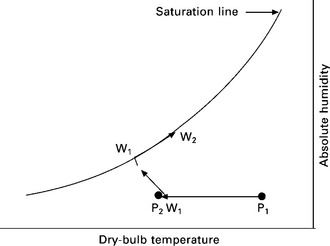
17.6 Psychrometric diagram indicating the heat and moisture transfer in an evaporative cooling system.
The cooling efficiency of the indirect evaporative cooling system is defined as:

The cooling efficiency will depend largely on the logarithmic average temperature difference (ΔTm) between the two airstreams. The larger the ΔTm, the higher the cooling efficiency will be. The definition of ΔTm can be expressed as follows:

At any position in the channels, heat transfer from the dry airstream to the wet surface of the wall can be expressed as:

Combining Eq. 17.3 and Eq. 17.4 yields:

As mentioned previously, the heat from the dry side is partly used for vaporising the water on the wet side of the wall, and the rest for increasing the temperature of the working air in the wet channel. however, if the heat from the dry side is used completely in vaporising the water on the wet side of the wall with no sensible heat transfer between the product and working airstreams, the system will achieve its maximum cooling efficiency, as the logarithmic average temperature difference between the two airstreams reaches its highest value. In this case, the working air temperature will remain constant along its pathway, which is equal to the wet side surface temperature (tw = tw,s), but its moisture content will rise along the flow path. For this particular circumstance, the evaporation rate on the wet side surface can be expressed as:
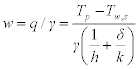
It can be seen from Eq. 17.6 that both air flow conditions (h, Tp, Tw,s) and material thermal properties (k, δ) affect the cooling performance of the system. In terms of air flow, a greater temperature difference between the airstreams in the dry and wet channels would enhance heat/mass transfer in the system, as would increasing the speeds of air flow in both dry and wet channels. In terms of material thermal properties, water retaining capability (Wr), thermal conductivity (k) and wall thickness (δ) are potential factors that may impact system performance.
Since heat/mass exchange walls are usually thin, with thickness (δ) ranging from 0.1 to 0.5 mm, their thermal resistance (δ/k) is low, although the value of thermal conductivity (k) may vary widely (between 5 and 300 W/m · °C). Given this, water retaining ability (Wr) is important for cooling effectiveness. Insufficient water retention would reduce the amount of evaporation and so reduce cooling efficiency, while surplus water retention would result in water accumulating on the wet side of the material, which would retard heat/mass transfer.
In air conditioning applications, the wet surface temperature, Tw,s, could be taken as the inlet working air wet-bulb temperature (the lowest possible level), which is around 15 °C for the UK climate [7]. The product air temperature, Tp, could be as high as 35 °C. Thus the Tp – Tw,s would be about 20 °C or less, and h is usually less than 20 W/m2 · °C for a heat exchanger [8]. The latent heat of water vaporisation, γ, could be expressed as:
where Twb is the wet-bulb temperature of the contact surface above the water film. If it was 15 °C, γ would be 2464 J/g.
Substituting these values into Eq. 17.6 yields,

The thickness of the wall, δ, is in the range of 0.1 to 0.5 mm, while thermal conductivity, k, takes the weighted average of the k values of the materials and the water, owing to the porous structure. Thus k can be written as [9]:
where the k value of the water is about 0.6 W/m · °C. For commonly used wall materials, such as metal, fibre, ceramics, zeolite and carbon, k values range from 0.3 to 300 W/m · °C, and porosity varies between 20% and 90%, as shown in Tables 17.1 to 17.4.

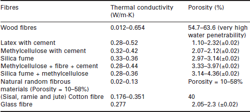
Table 17.3
Thermal conductivity of various ceramics
| Kinds of porous ceramics | Thermal conductivity (W/m · K) |
| SiC/SiC composites (conventional process) (porosity = 33.0%) | 0.08–15 |
| SiC/SiC composites (chemical vapour deposition) (porosity = 33.0 ± 0.6%) | 18.5–32.5 |
| SiC/SiC composites (polymer impregnation and pyrolysis) (porosity = 32.4 ± 0.4%) | 19–50 |
| Zirconia ceramics (porosity = 0–100%) | 0–2.2 |
| Zirconia toughened alumina (a) (porosity = 40%) | 11.09 |
| Zirconia toughened alumina (b) (porosity = 22%) | 21.67 |
| Zirconia toughened alumina (c) (porosity = 15%) | 22.79 |
| ZrO2 | 3.1 |
| Al2O3 | 29 |
| Aluminum nitride and polystyrene composites (porosity = 0–40) | 20–240 |

Substituting these values into Eq. 17.9 yields the k value of the watersaturated wall, which is in the range of 0.57 (ceramics with 90% porosity) to 270.06 W/m · °C (metal with 20% porosity).
Assuming a wall thickness of 0.5 mm, then the yield value of δ/k would be in the range 0.88 × 10− 3 to 1.85 × 10− 6 m2 · °C/W. Substituting this into Eq. 17.8, the evaporation rate w can then be obtained, which is in the range 0.1592–0.16194 g/m2 · s, i.e., 0.57312–0.58298 l/m2 · h. If these figures are applied to Eq. 17.6, the heat transfer rate across the wall is then obtained, which in this example would be about 392–399 W/m2. Assuming the void space is completely filled with water, the water retaining volume of a 0.5 mm thick wall would be in the range 0.1–0.45 litre, which is able to support 0.3–1 h of evaporation in an air conditioning application.
The above analysis shows that the thermal conductivity and water retaining capability (porosity) of the material have little impact on the magnitude of heat and mass transfer rates, and are therefore not important considerations for material selection. The water retaining capacity of the material is greater than that needed to support the evaporation, so the wet surface of the wall will not dry out.
Other criteria relevant to material selection include shape formation/holding ability, durability, compatibility with waterproof coatings, contamination risk and cost. Shape formation/holding ability describes the level of difficulty in shaping a material and whether it holds that shape effectively, and is evaluated by Young’s modulus, in Pascal (Pa). A moderate hardness is preferable, as hard material is difficult to shape, while soft material will not hold a shape. Durability refers to how long the material will work under saturated conditions. Compatibility indicates how the material adapts to other media, for instance substances used for waterproofing the material. This is particularly relevant for indirect evaporative cooling, since the material will be wet on one side and dry on the other and so one side needs to be waterproofed to prevent water penetration. The waterproof coating could be made of the same material as the wall, or some other material which is compatible with the wall material. Contamination risks indicate the possibility of bacterial growth under wet operating conditions, and cost is an important factor when determining the type of material to use.
17.3 Comparative analyses of potential materials for evaporative cooling
17.3.1 Metal
Traditional metal heat exchangers are made mainly of aluminium, copper and their alloys, which are shaped into an exchanger surface such as a plate or tube. To increase surface capillary force, and thus improve its ability to retain water for evaporative cooling, the surface on one or both sides of the sheet or tube is covered with a porous wick structure [10]. Several porous metal structures, wicked metal, metal foams and wools, will be described in this section. Table 17.1 gives the thermal conductivity of copper, aluminium and their alloys [11, 12].
The wick may be in the form of sintered particles, microscopic holes, meshes, grooves or whiskers, and is attached to the tube or sheet to hold water for evaporation. The porosity of the wick varies widely, from 20% to 90%, depending upon its construction, density and configuration. Fig.17.7 shows a whiskered tube heat exchanger, which has a large volume of micro-cavities on the external surface of the tube [13]. The density of metal whiskers covering the tube determines the porosity of the tube surface. For water retention, this structure is usually better than making holes or grooves on the tube.

In recent years, highly conductive foams based on copper or aluminium have been used to make heat exchangers. These foams have open cell structures that allow heat to be removed from or added to gases or liquids by letting them flow through the cooled or heated foam [14]. Owing to the open porous structure, this type of heat exchanger can contain plenty of water and so allow moisture transfer as well. The foams are produced using different methods, including melts, powders, sputtering and deposition [15]. Each method covers a characteristic range of density, cell size and cell topology, thus resulting in porosity ranging from 30% to 80%. At present, pore sizes ranging from 4.5–0.5 mm at constant porosity of 80% have been achieved. Porosity, shape information and construction expense are related to each other [15]. Figure 17.8 shows some commonly available metal foams [16].

Metal wools are the other type of porous metal used, and are made mainly from copper, aluminium and steel. Porosity varies, based on metal fibre length, fibre diameter and density, and ranges from 30% to 95%. The porosity of one kind of copper wool was found to be 0.95 and the thermal conductivity of this form of copper reduced to 1.0–2.7 W/m · K [17]. Figure 17.9 shows some commonly available metal wools [18].

If any of the above materials are used as the exchanger panel in an indirect evaporation cooling system, one side of the panel has to be waterproofed to prevent penetration of moisture. This can be achieved by attaching a thin solid film of the same material onto the porous metal.
Analysing the materials using the method given in Section 17.2 above showed that the thermal conductivity and porosity of any metal structure are both high enough to allow the heat/mass transfer necessary for air conditioning applications. This means that any of the metal types described is suitable for use as the exchanger plate, and the thermal properties of the metals are the least important factors in material selection.
In terms of hardness, copper and aluminium have Young’s moduli ranging from 70 to 140 GPa, giving them suitable shaping and shape-holding properties for the exchanger plate [19], [20]. Copper and aluminium are also durable and compatible with solid metal of the same material. In terms of risk of bacterial growth, metal plates with wick (sintered, meshed, grooved or whiskered) are better than foams and wools, as the pores on the wicked plates are exposed rather than concealed, facilitating cleaning or other hygiene treatments of the surface. In terms of cost, aluminium is much cheaper than copper [21].
17.3.2 Fibre
Fibrous materials, such as paperboard, cloth, wood or glass fibre, and others, have relatively high penetrability and lower thermal conductivity and hardness. Figure 17.10 shows the structure of a hardwood fibre, and Table 17.2 presents the thermal conductivity of various fibrous materials [22]–[25]. It can be seen that the fibres have much lower thermal conductivity than metals, ranging from 0.01 to 0.3 W/m · K [26]. Solid fibres have lower thermal conductivity than porous ones [25]. Table 17.2 also gives the porosity of a number of commonly used fibre materials. Wooden fibre, natural random fibre and glass fibre have the same level of porosity, ranging from 10 to 60%, while the others have a much lower level, ranging from 1 to 5%.

The effective thermal conductivity of a fibrous material increases with the fibre length, and approaches a stable level when the fibre length is sufficiently long. The effective thermal conductivity decreases as porosity increases [27]. Although the thermal conductivities of fibres are much lower than those of metals, an analysis using the method given in Section 17.2 indicated that the fibres are still able to provide a heat transfer rate of 392–399 W/m2, which is sufficient for air conditioning applications.
Fibre porosities are also sufficient to retain the water needed for moisture transfer. It would be preferable to choose a fibre with low porosity, as this kind of fibre has lower water retaining capacity, which would enhance sensible heat transfer. Most of the fibres presented in Table 17.2 are suitable for use as heat exchanger material, except for wood and cotton.
In terms of hardness, most fibre materials are not strong enough to be used as exchanger plates. However, flax or wooden fibres are the exception, with Young’s moduli as high as 70 to 110 GPa in the longitudinal direction. The lifespan of most fibre exchangers is short, as the material is easily deformed or damaged when soaked with water, except for flax or wood fibre. Fibre is compatible with polyethylene, which is used to waterproof one side of the fibre to prevent water penetration [28]. Wet fibre surfaces are readily contaminated by bacteria, which is not good for evaporative cooling applications. However, fibres are extremely cheap [28], and so frequent replacement is affordable, potentially overcoming the difficulties of short lifespan and contamination risk.
17.3.3 Ceramics
Porous ceramics have potential for use in evaporative cooling due to their strength, high thermal conductivity, waterproof nature and durability. Porous solids, such as extruded monoliths with parallel channels and thin walls, and made of various oxide and non-oxide ceramics, ceramic foams and metal structure, can perform both moisture retaining and heat exchanging activities. Figure 17.11 presents several foam-structured porous ceramics made by IKTS [29].

The thermal conductivity of porous ceramics depends upon composition, pore size and distribution, porosity and the manufacturing process. It varies from 0.1 to 240 W/m · K. Generally the thermal conductivity decreases as porosity increases [30]. Table 17.3 shows the thermal conductivity of a range of different ceramics [29], [31]–[33].
The water retaining capacity of ceramics increases with increasing porosity and pore size. One way to make porous ceramics is by mixing ground vermiculite and allophone at 600–800 °C [34].
The thermal conductivities of ceramics are higher than those of fibres, but lower than those of metals. This is sufficient for the heat/mass transfer needed in an air conditioning application. The porosities of ceramics are also sufficient to retain the water needed for moisture transfer. A ceramic with low porosity is preferable, because it has lower water retaining capacity thus enhancing sensible heat transfer. Aluminium nitride and polystyrene composites can be made at low porosity levels, such as 1% or below, and therefore may be suitable for use in this application. A porous ceramic may be combined with a thin film made of the same material to prevent penetration of moisture when being used in indirect evaporation systems.
In terms of hardness, most porous ceramics have Young’s moduli ranging from 50 to 400 GPa [35]–[38], making them suitable for use as exchanger plates. Porous ceramics are durable in wet conditions, and are compatible with solid film of the same material. Their porous structure is likely to be susceptible to bacterial growth when wet, and as the pores are concealed inside the structure, cleaning is difficult. Ceramics cost about twice as much as metal heat exchanger plates [39].
17.3.4 Zeolites
Zeolites can be classified as natural and synthetic zeolites. Natural zeolites are aluminosilicate minerals. They occur in nature and are mined rather than synthesised. Zeolites have a very open crystalline lattice that allows molecules like water vapour to be held inside the crystal itself like an object in a cage. Particular atoms of an aluminosilicate determine the size of the openings between the ‘bars’ of the cage, which in turn governs the maximum size of the molecule that can be adsorbed into the structure. Synthetic zeolites, also called molecular sieves, are crystalline aluminosilicates manufactured in a thermal process. Controlling the temperature of the process and the composition of the ingredient materials allows close control of the structure and surface characteristics of the adsorbent. At a somewhat higher cost, this provides a much more uniform product than naturally occurring zeolites.
Crystalline zeolites can be used for a wide variety of purposes including static and dynamic drying, ion exchange, and selective separations involving gases and liquids. Industrial applications of zeolites are primarily as Linde Molecular Sieves (LMS) and Davison Microtraps, due to availability in quantity and cost. Synthetic zeolites are attractive for drying and separation owing to their affinity for water and other small diameter molecules, and also their ability to reject large diameter molecules [40].
The thermal conductivity of LMS is around 0.59 W/m · K, which is much smaller than that of metals or porous ceramics [40]. However, the figure is still high enough to provide adequate heat transfer for air conditioning applications.
Linde Molecular Sieves have a high sorption capacity at low water vapour concentrations, and maintain their high sorption capacity at elevated relative humidity, which is in direct contrast to silica gel and activated alumina [41]. They have a porosity of 40–80%, but the absorption capacity is even higher due to water affinity characteristics. The water retaining potential is good enough to make LMS suitable for the moisture transfer requirements of air conditioning applications.
Zeolite material used in the exchanging wall can be coated with polyethylene or wax [42, 43] on one side to prevent moisture penetration when being used in indirect evaporation systems.
In terms of hardness, most zeolites are adequately strong for use as exchanger plates, having Young’s moduli ranging from 1 to 20 GPa [44]. Since the pores are internal, the zeolite structure is susceptible to bacterial growth when wet. In terms of cost, they are more expensive than ceramics [39].
17.3.5 Carbon
Carbon fibres are important as reinforcement in composite materials because of their low density, high strength (up to 7 GPa) and tensile modulus up to 600 GPa. Carbon fibre is also useful in a wide variety of products due to its high electrical and thermal conductivity [45]. Activated carbons are often used for desiccants, carbon–carbon composites are commonly used in aerospace applications, and mesophase pitch-based carbon fibres with high preferred orientation have low density and high thermal conductivity (k), with a k value at room temperature up to 1120 W/m · °C. Figure 17.12 shows three types of carbon fibre structure [46–48].

17.12 Three types of carbon fibre structures (a) laminated short fibre felt; (b) laminated carbon cloth felt; (c) needle picked long fibre felt.
Activated carbons have very low thermal conductivity (0.2 W/m · K), resulting in severe thermal limitations due to low overall adsorption and desorption kinetics as well as secondary reaction products or hazards in industrial applications. The in situ activation of various precursors within a consolidated expanded natural graphite matrix results in composites with high thermal conductivities (from 1 to 32 W/m · °C) and high effective adsorbent levels (80 wt%) [45]. The type of carbon fibres in the composites plays an important role in thermal conduction behaviour and the highly graphitic flat-layered structured fibres conduct in a direction parallel to the fibre axis [46]. Table 17.4 presents the thermal conductivity and porosity of selected carbon fibre materials [47–55].
Analysis using the method given in Section 17.2 indicates that the thermal properties of carbon materials are good enough to transfer both sensible and latent heat in air conditioning applications. A carbon material with low porosity would be preferable, as the resultant lower water retaining capacity would enable enhanced sensible heat transfer. Carbon fibres or mesophase pitch-based fibres could be made at low porosity levels, such as 1% or below, and therefore may be suitable for use in this application. Carbon fibres used in a heat exchanging wall can also be coated with polyethylene or wax on one side to prevent moisture penetration when being used in indirect evaporation systems [56, 57].
In terms of stiffness, carbon fibres are strong enough to be formed into heat/mass transfer elements, having Young’s moduli ranging from 1 to 220 GPa [44]. Since the pores are internal, a carbon fibre structure is likely to be susceptible to bacterial growth when wet for a long time. In terms of cost, carbon fibre materials have similar prices to metals [39].
17.3.6 Comparing the materials
Table 17.5 summarises the performance of the materials described above in terms of thermal conductivity, porosity, hardness, compatibility with coating materials, contamination risk and cost.

All the materials described have thermal properties suitable for the heat/ mass transfer required in air conditioning applications (up to 390 W/m2), so it is unnecessary to consider the impact of thermal conductivity and porosity on thermal performance when selecting one of these materials for a heat/mass exchanger. Thus the most important factors to be considered are hardness, compatibility with coating materials, contamination risk and cost. Metal and ceramics are better choices for hardness (shaping and shape-retaining ability), followed by zeolite, carbon and fibre. All the selected materials are compatible with a specific coating and therefore they have comparable performances in this respect. For contamination considerations, wicked (sintered, meshed, grooved or whiskered) metal plate is the best material, while the others are subject to contamination. From the cost point of view, fibre is the cheapest material, followed by metal and carbon. Ceramics and zeolite are the most expensive materials and are therefore not cost effective.
In summary, for a durable and healthy air conditioning system, wicked metal plates (copper or aluminium) are the preferable option for heat/mass transfer materials. They are cheaper than ceramics and zeolites, about the same price as carbons, but more expensive than fibres. This price level is acceptable when the other benefits of metals are taken into account.
17.4 Potential applications of porous materials in buildings
17.4.1 Evaporative cooling
The porous materials discussed above could be used in evaporative cooling in different ways. The most common application is in heat and mass exchangers. Some types of porous materials, including metal wools/foams and ceramics, could be used in the façades of buildings to allow passive or active cooling of the internal spaces. For the direct cooling façade pattern shown in Fig.17.13, warm air would be drawn from outside, pass across the wet surface of the façade, where heat and moisture exchange would occur, and finally be delivered into the building at a cooler temperature.

To avoid adding moisture to the air, a façade made of porous materials could also be designed as an indirect cooling structure, which would allow air to be cooled without adding moisture. A diagram of an indirect cooling module for a façade is shown in Fig. 17.14. It is based on integrating a porous media (cast or sintered ceramic, metal foam) water container and an array of finned heat pipes. This type of system employs air and water as the working fluids, and is suitable for use in different types of buildings, including high-rise buildings, housing estates or office blocks.

Each module is a curtain wall unit made up of three layers: an outer weatherproof layer, a middle-layer divided into two parts (with an upper cavity containing a slim water-containing porous panel and surrounding space for air movement, and a number of finned heat pipes arrayed in a row, with their upper non-finned parts inserted into the water container, and the lower finned parts extending to a separate cavity below), and an inner layer made of water-resistant internal wall panel. All these modules could be integrated into a building façade, and share a common water tank situated at a convenient point in the building. The water tank could supply water to all the containers using a valve for control, and allow the over-charged water to be collected at certain intervals by the use of a pump fitted on the return line. A schematc of the module-integrated façade in a building is shown in Fig. 17.15.

In the module, outdoor air enters the outer cavity of the sandwich wall through air grilles on the lower part of the outer layer. The air then flows over the surface of a porous panel, which forms part of the mid-layer of the wall. The air movement aids water evaporation off the surface of the panel, and channels the water-laden air out into the atmosphere. However, the main cause of water evaporation is heat loss from the pipes contained in the upper part of the module. This heat loss enables the pipes to transfer heat energy away from the inner cavity of the sandwich wall, in turn drawing room air into the cavity to be cooled. The cooled air can then be delivered to the room space using a mini fan, thus creating a cooling effect in the building. The layout in Fig. 17.15 allows the lower part of the inner cavity of the sandwich wall to act as a fan-coil unit.
Use of such modules in walls could enable a passive evaporative cooling device to be integrated into building construction, allowing indirect evaporative cooling to be utilised in buildings on a large scale.
17.4.2 Other applications
Porous materials have other uses in buildings apart from evaporative cooling. Examples of these applications are given below.
Cellulose fibre
Cellulose fibre could be used for making air-to-air heat and mass exchangers to recover energy from outgoing air. A diagram of a recently developed cellulose fibre heat and mass exchanger is shown in Fig. 17.16. The device exchanges heat and moisture between two airstreams through adjacent fibre membranes. The membranes are separated by guides that run the length of one sheet and the width of the next sheet. This allows the development of an almost infinite number of energy exchange microenvironments between the two airstreams, and energy (enthalpy) exchange efficiencies range from 70% to 80% [58].

Two coating methods, adsorbent (CaCl) finishing and absorbent (LiCl) filming, were applied to the surface of the cellulose fibre to further enhance its energy (enthalpy) efficiency. It was found that both methods have potential to improve energy exchange efficiency, particularly moisture transfer efficiency of the exchanger. This is because coating increased the moisture infiltration coefficients of the membrane, and also the convective mass transfer coefficients on both sides of the membrane. For the given exchanger geometries and operating conditions, the absorbent filming had the most significant impact on exchanger efficiency, with its enthalpy efficiency being about 15.9% higher than the adsorbent finishing, and 25.6% higher than the uncoated fibre. These two coating methods significantly affect the moisture exchange efficiency of cellulose fibres. Absorbent filming can achieve 84.5% moisture exchange efficiency, which is 38.7% and 28.1% higher than those of uncoated fibres and adsorbent finishing, respectively. With the adsorbent finishing and absorbent filming, the sensible heat transfer efficiency was increased by 5.9% and 9.0% respectively, due to the increased thermal conductivity of the membrane caused by the coatings [59].
Porous metals
Porous metals are known to be useful in heat exchangers for air conditioning applications in buildings. An interesting application for porous metals is in heat pipe technology, which usually employs wicked metal tubes or plates, with varied wick structures (including sintered particles, microscopic holes, meshes, grooves or whiskers). These structures enable the working fluid to return easily from the condensation section to the evaporation section under the action of the capillary force generated by the wicks. The wicked heat pipe and its working principles are shown schematically in Fig. 17.17.

Ceramics
Ceramics are commonly used to make various building components, such as walls, roofs, baths, basins and others, which are characteristically lightweight and have a long lifespan. Ceramics are also used in sound attenuation apparatus as the numerous pores within the ceramics can absorb sound effectively. An interesting application of ceramics is the perspiration wall, which can lead to natural ventilation and dynamic thermal insulation.
Zeolites
In air conditioning applications in buildings, zeolites are commonly used as adsorbents which dehumidify and humidify air.
Carbons
In buildings, activated carbons are most frequently used for adsorption of gases other than water vapour because they have a greater affinity for the nonpolar molecules typical of organic solvents. Like other adsorbents, carbons have a larger internal surface and especially larger capillaries. This capillary volume gives them a high capacity to adsorb water vapour at relative humidities of 45 to 100%.
17.5 Conclusions
There are five major types of materials used in heat and mass transfer applications: metal, cellulose fibre, zeolite, ceramic and carbon. Each type of material has an optimum configuration when being used as a heat/mass transfer medium in evaporative cooling systems. Metals used in these systems are in the form of wicked (sintered, meshed, grooved or whiskered) copper or aluminium sheets; fibres are wooden or flax fibres with low porosity; ceramics have a metal-based structure with low porosity; and zeolite and carbon materials tend to have low porosity and high thermal conductivity.
The heat and mass transfer characteristics of these materials when used in heat/mass exchangers for air conditioning applications were investigated. Heat transfer rates were found to be in the range of 392–399 W/m2, and moisture evaporation rates between 0.57 and 0.58 l/m2 · h. These rates are relatively low, indicating that the thermal properties of the selected materials, i.e., thermal conductivity and porosity, have very little impact on the process. Thus these two parameters play minor roles when selecting heat and mass exchanging materials. Instead, shape formation/holding ability, durability, compatibility with coating materials, contamination risk and cost become more important concerns.
As indirect evaporative cooling requires product air to be cooled without adding moisture, a waterproof coating is needed on one side of the exchanging sheet. Each of the materials are compatible with specific coatings and therefore there were no distinct differences in terms of coating compatibility.
The material used for evaporative cooling needs to be formed into defined shapes that are durable, and metal and ceramic materials are better than zeolite, carbon and fibre in this regard.
As the wet channels are always soaked with water, there is a high risk of bacterial growth within the porous structure, particularly interior pores. To avoid this, an exposed pore structure is preferable, permitting frequent cleaning and sterilization of the material. A wicked metal (copper or aluminium) is the most suitable material in this regard.
In terms of cost, fibre is the cheapest of the five materials. Metals and carbons cost more than fibres but less than ceramics and zeolites.
In summary, wicked metals (copper or aluminium) are the most suitable materials for evaporative cooling applications. Wicked aluminium sheet is much cheaper than copper sheet with the same structure, and therefore preferred. Porous materials also have a range of other uses in buildings and building services, including as dehumidifiers, humidifiers, in structural applications and for soundproofing.
17.6 References
1. http://www.idalex.com/technology/how_it_works_-_engineering_perspective.htm.
2. Lertsatitthanakorn, C., Rerngwongwitaya, S., Soponronnarit, S. Field experiments and economic evaluation of an evaporative cooling system in a silkworm rearing house. Biosystems Engineering. 2006; 93(2):213–219.
3. Stoitchkov, N.J., Dimitrov, G.I. Effectiveness of crossflow plate heat exchanger for indirect evaporative cooling. International Journal of Refrigeration. 1998; 21(6):463–471.
4. Maisotsenko, V., Method and plate apparatus for dew point evaporative cooler United States Patent 6,581,402. June 24, 2003.
5. Zhao, X., Li, J., Riffat, S.B. Numerical study of a novel counter-flow heat and mass exchanger for dew point cooling system. Applied Thermal Engineering. 2008; 28:1942–1951.
6. Zhao, X., Liu, S., Riffat, S.B. Comparative study of the heat and mass exchanging materials for the indirect evaporative cooling systems. Building and Environment. 2008; 43:1902–1911.
7. CIBSE Guide A, Environmental Design. Page Bros. (Norwich) Ltd.: Norwich, 2001; 2–6.
8. Heat Transfer. China Building Industry Press: Beijing, China, 1993; 297–298.
9. Parrott, J.E., Stuckes, A.D. Thermal Conductivity of Solids. London: Pion Limited, 1975; 201.
10. Tadrist, L., Miscevic, M., Rahli, O., Topin, F. About the use of fibrous materials in compact heat exchangers. Experimental Thermal and Fluid Science. 2004; 28:193–199.
11. Schweitze, P.A.Metallic Materials, Physical, Mechanical and Corrosion Properties. Boca Raton, FL: Marcel Dekker, 2003.
12. Welty, J.R., Wicks, C.E., Wilson, R.E., Rorrer, G.L. Fundamentals of Momentum, Heat, and Mass Transfer. New York: John Wiley & Sons, 2000; 723–724.
13. Schulz, A., Akapiev, G.N., Shirkova, V.V., Rösler, H., Dmitriev, S.N. A new method of fabrication of heat transfer surfaces with micro-structured profile. Nuclear Instruments and Methods in Physics Research B. 2005; 236:254–258.
14. Banhart, J. Manufacturing, characterisation and application of cellular metals and metal foams. Progress in Materials Science. 2001; 46:559–632.
15. Clyne, T.W., Simancik, F. Metal Matrix Composites and Metallic Foams, EUROMAT; Volume 5. Weinheim, New York, 2000.
16. http://www.ifam-dd.fraunhofer.de/fhg/ifam_dd/EN/gebiete/schaum/index.jsp.
17. Lacroix, C., Ramany, Bala P., Feidt, M. Evaluation of the effective thermal conductivity in metallic porous media submitted to incident radiative flux in transient conditions. Energy Conversion & Management. 1999; 40:1775–1781.
18. http://www.briwax-online.com/GMT.html.
19. Pelletier, H. Predictive model to estimate the stress–strain curves of bulk metals using nanoindentation. Tribology International. 2006; 39:593–606.
20. Piggott, M. Load Bearing Fibre Composites, 2nd edn. London: Kluwer Academic Publishers, 2002.
21. RS Catalogue Data 5, Mechanical, UK, 2004, 5 (150) – 5 (170).
22. Sevostianov, I., Kachanov, M. Connection between elastic moduli and thermal conductivities of anisotropic short fiber reinforced thermoplastics: theory and experimental verification. Materials Science and Engineering. 2003; A360:339–344.
23. Fan, L., Hu, Y., Tian, T., Yu, Z. The prediction of effective thermal conductivities perpendicular to the fibres of wood using a fractal model and an improved transient measurement technique. International Journal of Heat and Mass Transfer. 2006; 49:4116–4123.
24. Fu, X., Chung, D. Effects of silica fume, latex, methylcellulose, and carbon fibers on the thermal conductivity and specific heat of cement paste. Cement and Concrete Research. 1997; 27(12):1799–1804.
25. Thunman, H., Leckner, B. Thermal conductivity of wood – models for different stages of combustion. Biomass and Bioenergy. 2002; 23:47–54.
26. Gaier, J., Yoder, Vandenberg Y., Berkebile, S., Stueben, H., Balagadde, F. The electrical and thermal conductivity of woven pristine and intercalated graphite fiber–polymer composites. Carbon. 2003; 41:2187–2193.
27. Wang, M., He, J., Yu, J., Pan, N. Lattice Boltzmann modelling of effective thermal conductivity for fibrous materials. International Journal of Thermal Science. 2007; 46(9):848–855.
28. Coolerado, Coolerado HMX (Heat and Mass Exchanger) Brochure. USA: Coolerado Corporation, Arvada, Co, 2006.
29. Fend, T., Hoffschmidt, B., Pitz-Paal, R., Reutter, O., Rietbrock, P. Porous materials as open volumetric solar receivers: experimental determination of thermophysical and heat transfer properties. Energy. 2004; 29:823–833.
30. Nait-Ali, B., Haberko, K., Vesteghem, H., Abse, J., Smith, D.S. Thermal conductivity of highly porous zirconia. Journal of the European Ceramic Society. 2006; 26:3567–3574.
31. Taguchi, T., Igawa, N., Yamada, R., Jitsukawa, S. Effect of thick SiC interphase layers on microstructure, mechanical and thermal properties of reaction-bonded SiC/ SiC composites. Journal of Physics and Chemistry of Solids. 2005; 66:576–580.
32. Pezzotti, G., Kamada, I., Miki, S. Thermal conductivity of AlN/polystyrene interpenetrating networks. Journal of the European Ceramic Society. 2000; 20:1197–1203.
33. Itatani, K., Tanaka, T., Davies, I.J. Thermal properties of silicon carbide composites fabricated with chopped Tyranno® Si- Al- C fibres. Journal of the European Ceramic Society. 2006; 26:703–710.
34. Okada, K., Matsui, S., Isobe, T., Kameshima, Y., Nakajima, A. Water-retention properties of porous ceramics prepared from mixtures of allophone and vermiculite for materials to counteract heat island effects. Ceramics International. 2006; 10:1–6.
35. Pabst, W., Gregorová, E., Tichá, G. Elasticity of porous ceramics – a critical study of modulus–porosity relations. Journal of the European Ceramic Society. 2006; 26:1085–1097.
36. Burkes, D., Gottoli, G., Moore, J.J. Mechanical properties of porous combustion synthesized Ni3Ti-TiCx composites. Composites Science and Technology. 2006; 66:1931–1940.
37. Jeong, H., Hsu, D. Quantitative estimation of material properties of porous ceramics by means of composite micromechanics and ultrasonic velocity. NDT&E International. 1996; 29(2):95–101.
38. Krauß, G., Kubler, J., Trentini, E. Preparation and properties of pressureless infiltrated SiC and A1N particulate reinforced metal ceramic composities based on bronze and iron alloys. Materials Science and Engineering. 2002; A337:315–322.
39. http://www.goodfellow.com/scripts/web.wl?MGWLPN=MNT&PROG=SEARTOW&LAN=A&HEAD=ZZCAAAAC&SPAGE=C%204l.
40. Hersh, C.K.Molecular Sieves. New York: Reinhold Publishing Corporation, Chapman & Hall, Ltd, London, 1961.
41. Jeong, J., Mumma, S.A. Practical thermal performance correlations for molecular sieve and silica gel loaded enthalpy wheels. Applied Thermal Engineering. 2005; 25:719–740.
42. http://www.patentstorm.us/patents/5846696-description.html.
43. http://www.patentstorm.us/patents/6180708-description.html.
44. Metin, D., Tihminlioglu, F., Balköse, D., Ülkü, S. The effect of interfacial interactions on the mechanical properties of polypropylene/natural zeolite composites. Composites: Part A. 2004; 35:23–32.
45. Py, X., Daguerre, E., Menard, D. Composites of expanded natural graphite and in situ prepared activated carbons. Carbon. 2002; 40:1255–1265.
46. Manocha, L.M., Warrier, A., Manocha, S., Sathiyamoorthy, D., Banerjee, S. Thermophysical properties of densified pitch based carbon/carbon materials – I. Unidirectional composites. Carbon. 2006; 44:480–487.
47. Liu, Z., Zhang, G., Li, H., Sun, J., Ren, M. Al infiltrated C–C hybrid composites. Materials and Design. 2005; 26:83–87.
48. Ma, Z., Shi, J., Song, Y., Guo, Q., Shai, G., Liu, L. Carbon with high thermal conductivity, prepared from ribbon-shaped mesophase pitch-based fibers. Carbon. 2006; 44:1298–1301.
49. Yamada, R., Igawa, N., Taguchi, T. Thermal diffusivity/conductivity of Tyranno SA fiber- and Hi-Nicalon Type S fiber-reinforced 3-D SiC/SiC composites. Journal of Nuclear Materials. 2004; 329–333. [497-501].
50. Frusteri, F., Leonardi, V., Vasta, S., Restuccia, G. Thermal conductivity measurement of a PCM based storage system containing carbon fibers. Applied Thermal Engineering. 2005; 25:1623–1633.
51. Sivakumar, R., Guo, S., Nishimura, T., Kagawa, Y. Thermal conductivity in multi-wall carbon nanotube/silica-based nanocomposites. Scripta Materialia. 2007; 56:265–268.
52. Wanner, A. Elastic modulus measurements of extremely porous ceramic materials by ultrasonic phase spectroscopy. Materials Science and Engineering. 1998; A248:35–43.
53. Wang, Y., Tan, S., Jiang, D. The effect of porous carbon preform and the infiltration process on the properties of reaction-formed SiC. Carbon. 2004; 42:1833–1839.
54. Wang, X.L., Zhang, H.M., Zhang, J.L., Xu, H.F., Tian, Z.Q., Chen, J., Zhong, H.X., Liang, Y.M., Yi, B.L. Micro-porous layer with composite carbon black for PEM fuel cells. Electrochimica Acta. 2006; 51:4909–4915.
55. Straatman, A.G., Gallego, N.C., Thompson, B.E., Hangan, H. Thermal characterization of porous carbon foam – convection in parallel flow. International Journal of Heat and Mass Transfer. 2006; 49:1991–1998.
56. http://www.ncbi.nlm.nih.gov/sites/entrez?cmd=Retrieve&db=PubMed&list_uids=11199307&dopt=Abstract
57. http://www.patentstorm.us/patents/5539035-description.html.
58. , Catalogue data of the fibre heat and mass exchanger, manual. Hangzhou ISAW Technology Corporation, China, 2005. [310018].
59. Liu, S., Riffat, S., Zhao, X., Yuan, Y. Impact of adsorbent finishing and absorbent filming on energy exchange efficiency of an air-to-air cellulose fibre heat and mass exchanger. Building and Environment. 2009; 44:1803–1809.
17.7 Appendix: Nomenclature
h heat convective coefficient, W/m2;
k thermal conductivity of the heat transfer wall, W/m · °C;
q heat flux across 1 m2 of heat transfer area, W/m2;
r porosity of the wall material;
Us the overall heat transfer coefficient from dry air flow to the opposite wet wall surface, W · m2, °C;
w water evaporation rate on the wet surface of the wall, kg/s;
δ thickness of the heat transfer wall, m;
η cooling efficiency of the evaporative cooling system;
γ latent heat of water evaporation, J/kg;
ΔTm Logarithmic average temperature difference between the two airstreams, °C