
Chapter 5. Acceleration, Shock, and Vibration
5.1. Introduction
Accelerometers are sensing transducers that provide an output proportional to acceleration, vibration, and shock. These sensors have found a wide variety of applications in both research and development arenas along with everyday use. In addition to the very technical test and measurement applications, such as modal analysis, NVH (noise vibration and harshness), and package testing, accelerometers are also used in everyday devices such as airbag sensors and automotive security alarms. Whenever a structure moves, it experiences acceleration. Measurement of this acceleration helps us gain a better understanding of the dynamic characteristics that govern the behavior of the object. Modeling the behavior of a structure provides a valuable technical tool that can then be used to modify response, to enhance ruggedness, improve durability, or reduce the associated noise and vibration.
The most popular class of accelerometers is the piezoelectric accelerometer. This type of sensor is capable of measuring a wide range of dynamic events. However, many other classes of accelerometers exist that are used to measure constant or very low-frequency acceleration such as automobile braking, elevator ride quality, and even the gravitational pull of the earth. Such accelerometers rely on piezoresistive, capacitive, and servo technologies.
5.2. Technology Fundamentals
5.2.1. Piezoelectric Accelerometer
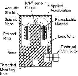
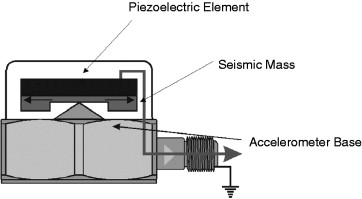
Piezoelectric accelerometers are self-generating devices characterized by an extended region of flat frequency response range, a large linear amplitude range, and excellent durability. These inherent properties are due to the use of a piezoelectric material as the sensing element for the sensor. Piezoelectric materials are characterized by their ability to output a proportional electrical signal to the stress applied to the material. The basic construction of a piezoelectric accelerometer is depicted in Figure 5.1.
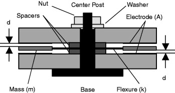
Figure 5.1. Basic piezoelectric accelerometer construction.

The active elements of the accelerometer are the piezoelectric elements. The elements act as a spring, which has a stiffness k, and connect the base of the accelerometer to the seismic masses. When an input is present at the base of the accelerometer, a force (F) is created on piezoelectric material proportional to the applied acceleration (a) and size of the seismic mass (m). (The sensor is governed by Newton's law of motion F = ma.) The force experienced by the piezoelectric crystal is proportional to the seismic mass times the input acceleration. The more mass or acceleration, the higher the applied force and the more electrical output from the crystal.
The frequency response of the sensor is determined by the resonant frequency of the sensor, which can generally be modeled as a simple single degree of freedom system. Using this system, the resonant frequency (ω) of the sensor can be estimated by:
![]() .
.
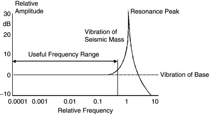
The typical frequency response of piezoelectric accelerometers is depicted in Figure 5.2.
Figure 5.2. Typical frequency response of piezoelectric accelerometer.
Piezoelectric accelerometers can be broken down into two main categories that define their mode of operation. Internally amplified accelerometers or IEPE (internal electronic piezoelectric) contain built-in microelectronic signal conditioning. Charge mode accelerometers contain only the self-generating piezoelectric sensing element and have a high impedance charge output signal.
5.2.1.1. IEPE Accelerometers
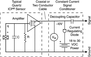
IEPE sensors incorporate built-in, signal-conditioning electronics that function to convert the high-impedance charge signal generated by the piezoelectric sensing element into a usable low-impedance voltage signal that can be readily transmitted, over ordinary two-wire or coaxial cables, to any voltage readout or recording device. The low-impedance signal can be transmitted over long cable distances and used in dirty field or factory environments with little degradation. In addition to providing crucial impedance conversion, IEPE sensor circuitry can also include other signal conditioning features, such as gain, filtering, and self-test features. The simplicity of use, high accuracy, broad frequency range, and low cost of IEPE accelerometer systems make them the recommended type for use in most vibration or shock applications. However, an exception to this assertion must be made for circumstances in which the temperature at the installation point exceeds the capability of the built-in circuitry. The routine upper temperature limit of IEPE accelerometers is 250° F (121° C); however, specialty units are available that operate to 350° F (175° C).
IEPE is a generic industry term for sensors with built-in electronics. Many accelerometer manufacturers use their own registered trademarks or trade name to signify sensors with built-in electronics. Examples of these names include: ICP® (PCB Piezotronics), Deltatron (Bruel & Kjaer), Piezotron (Kistler Instruments), and Isotron (Endevco), to name a few.
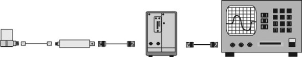
The electronics within IEPE accelerometers require excitation power from a constant-current, DC voltage source. This power source is sometimes built into vibration meters, FFT analyzers, and vibration data collectors. A separate signal conditioner is required when none is built into the readout. In addition to providing the required excitation, power supplies may also incorporate additional signal conditioning, such as gain, filtering, buffering, and overload indication. The typical system setups for IEPE accelerometers are shown in Figure 5.3.
Figure 5.3. Typical IEPE system.
5.2.1.2. Charge Mode Accelerometers
Charge mode sensors output a high-impedance, electrical charge signal that is generated directly by the piezoelectric sensing element. It should be noted that this signal is sensitive to corruption from environmental influences and cable-generated noise. Therefore it requires the use of a special low-noise cable. To conduct accurate measurements, it is necessary to condition this signal to a low-impedance voltage before it can be input to a readout or recording device. A charge amplifier or in-line charge converter is generally used for this purpose. These devices utilize high-input-impedance, low-output-impedance charge amplifiers with capacitive feedback. Adjusting the value of the feedback capacitor alters the transfer function or gain of the charge amplifier.
Typically, charge mode accelerometers are used when high-temperature survivability is required. If the measurement signal must be transmitted over long distances, it is recommended to use an in-line charge converter, placed near the accelerometer. This minimizes the chance of noise. In-line charge converters (Figure 5.4) can be operated from the same constant-current excitation power source as IEPE accelerometers for a reduced system cost. In either case, the use of a special low-noise cable is required between the accelerometer and the charge converter to minimize vibration induced triboelectric noise.
Figure 5.4. Typical in-line charge converter system.
Sophisticated laboratory-style charge amplifiers (Figure 5.5) usually include adjustments for normalizing the input signal and altering the feedback capacitor to provide the desired system sensitivity and full-scale amplitude range. Filtering also may be used to tailor the high- and low-frequency response. Some charge amplifiers provide dual-mode operation, which provides power for IEPE accelerometers and conditions charge mode sensors.
Figure 5.5. Laboratory charge amplifier system.

Because of the high-impedance nature of the output signal generated by charge mode accelerometers, several important precautionary measures must be followed. As noted previously, always be attentive to motion-induced (triboelectric) noise in the cable and mitigate by using specially treated cable. Also, always maintain high insulation resistance of the accelerometer, cabling, and connectors. To ensure high insulation resistance, all components must be kept dry and clean. This will help minimize potential problems associated with noise and/or signal drift.
5.2.1.3. Piezoelectric Sensing Materials
Two categories of piezoelectric materials that are predominantly used in the design of accelerometers are quartz and polycrystalline ceramics. Quartz is a natural crystal, while ceramics are man-made. Each material offers certain benefits. The material choice depends on the particular performance features desired of the accelerometer.
Quartz is widely known for its ability to perform accurate measurement tasks and contributes heavily in everyday applications for time and frequency measurements. Examples include everything from wristwatches and radios to computers and home appliances. Accelerometers benefit from several unique properties of quartz. Since quartz is naturally piezoelectric, it has no tendency to relax to an alternative state and is considered the most stable of all piezoelectric materials. This important feature provides quartz accelerometers with long-term stability and repeatability. Also, quartz does not exhibit the pyroelectric effect (output due to temperature change), which provides stability in thermally active environments. Because quartz has a low capacitance value, the voltage sensitivity is relatively high compared to most ceramic materials, making it ideal for use in voltage-amplified systems. Conversely, the charge sensitivity of quartz is low, limiting its usefulness in charge-amplified systems, where low noise is an inherent feature.
A variety of ceramic materials are used for accelerometers, depending on the requirements of the particular application. All ceramic materials are man-made and are forced to become piezoelectric by a polarization process. This process, known as poling, exposes the material to a high-intensity electric field. This process aligns the electric dipoles, causing the material to become piezoelectric. If ceramic is exposed to temperatures exceeding its range, or large electric fields, the piezoelectric properties may be drastically altered. There are several classifications of ceramics. First, there are high-voltage-sensitivity ceramics that are used for accelerometers with built-in, voltage-amplified circuits. There are high-charge-sensitivity ceramics that are used for charge mode sensors with temperature ranges to 400° F (205° C). This same type of crystal is used in accelerometers that use built-in charge-amplified circuits to achieve high output signals and high resolution. Finally, there are high-temperature piezoceramics that are used for charge mode accelerometers with temperature ranges over 1000° F (537° C) for monitoring engine manifolds and superheated turbines.
5.2.1.4. Structures for Piezoelectric Accelerometers
A variety of mechanical configurations are available to perform the transduction principles of a piezoelectric accelerometer. These configurations are defined by the nature in which the inertial force of an accelerated mass acts upon the piezoelectric material. There are three primary configurations in use today: shear, flexural beam, and compression. The shear and flexural modes are the most common, while the compression mode is used less frequently but is included here as an alternative configuration.
Shear Mode
Shear mode accelerometer designs bond, or “sandwich,” the sensing material between a center post and seismic mass (Figure 5.6). A compression ring or stud applies a preload force required to create a rigid linear structure. Under acceleration, the mass causes a shear stress to be applied to the sensing material. This stress results in a proportional electrical output by the piezoelectric material. The output is then collected by the electrodes and transmitted by lightweight lead wires to either the built-in signal conditioning circuitry of ICP sensors or directly to the electrical connector for a charge mode type. By isolating the sensing crystals from the base and housing, shear accelerometers excel in rejecting thermal transient and base bending effects. Also, the shear geometry lends itself to small size, which promotes high-frequency response while minimizing mass loading effects on the test structure. With this combination of ideal characteristics, shear mode accelerometers offer optimum performance.
Figure 5.6. Shear mode accelerometer.
Flexural Mode
Flexural mode designs utilize beam-shaped sensing crystals, which are supported to create strain on the crystal when accelerated (Figure 5.7). The crystal may be bonded to a carrier beam that increases the amount of strain when accelerated. The flexural mode enables low-profile, lightweight designs to be manufactured at an economical price. Insensitivity to transverse motion is an inherent feature of this design. Generally, flexural beam designs are well suited for low-frequency, low-gravitational (g) acceleration applications such as those that may be encountered during structural testing.
Figure 5.7. Flexural mode accelerometer.
Compression Mode
Compression mode accelerometers are simple structures that provide high rigidity (Figure 5.8). They represent the traditional or historical accelerometer design.
Figure 5.8. Compression mode accelerometer.
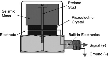
Upright compression designs sandwich the piezoelectric crystal between a seismic mass and rigid mounting base. A preload stud or screw secures the sensing element to the mounting base. When the sensor is accelerated, the seismic mass increases or decreases the amount of compression force acting upon the crystal, and a proportional electrical output results. The larger the seismic mass, the greater the stress and, hence, the greater the output.
This design is generally very rugged and can withstand high-gravitational shock levels. However, due to the intimate contact of the sensing crystals with the external mounting base, upright compression designs tend to be more sensitive to base bending (strain). Additionally, expansion and contraction of the internal parts act along the sensitive axis making the accelerometer more susceptible to thermal transient effects. These effects can contribute to erroneous output signals when used on thin sheet-metal structures or at low frequencies in thermally unstable environments, such as outdoors or near fans and blowers.
5.2.2. Piezoresistive Accelerometers
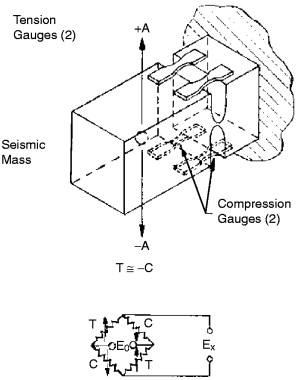
Single-crystal silicon is also often used in manufacturing accelerometers. It is an anisotropic material whose atoms are organized in a lattice having several axes of symmetry. The orientation of any plane in the silicon is provided by its Miller indices. Piezoresistive transducers manufactured in the 1960s first used silicon strain gauges fabricated from lightly doped ingots. These ingots were sliced to form small bars or patterns. The Miller indices allowed positioning of the orientation of the bar or pattern with respect to the crystal axes of the silicon. The bars or patterns were often bonded directly across a notch or slot in the accelerometer flexure. Figure 5.9 shows short, narrow, active elements mounted on a beam. The large pads are provided for thermal power dissipation and ease of electrical and mechanical connections. The relatively short web avoids column-type instabilities in compression when the beam bends in either direction. The gauges are subsequently interconnected in a Wheatstone bridge configuration. This fact that the gauges are configured in a bridge indicates that piezoresistive accelerometers have response down to DC (i.e., they respond to steady-state accelerations).
Figure 5.9. Bulk silicon resistors bonded to metal beam accelerometer flexure.
Since the late 1970s we have encountered a continual evolution of microsensors into the marketplace. A wide variety of technologies are involved in their fabrication. The sequence of events that occurs in this fabrication process are these: the single crystal silicon is grown; the ingot is trimmed, sliced, polished, and cleaned; diffusion of a dopant into a surface region of the wafer is controlled by a deposited film; a photolithography process includes etching of the film at places defined in the developing process, followed by removal of the photoresist; and isotropic and anisotropic wet chemicals are used for shaping the mechanical microstructure. Both the resultant stress distribution in the microstructure and the dopant control the piezoresistive coefficients of the silicon.
Electrical interconnection of various controlled surfaces formed in the crystal, as well as bonding pads, are provided by thin-film metallization. The wafer is then separated into individual dies. The dies are bonded by various techniques into the transducer housing, and wire bonding connects the metallized pads to metal terminals in the transducer housing. It is important to realize that piezoresistive accelerometers manufactured in this manner use silicon both as the flexural element and as the transduction element, since the strain gauges are diffused directly into the flexure. Figures 5.10 and 5.11 show typical results of this fabrication process.
Figure 5.10. MEMS piezoresistive accelerometer flexure.
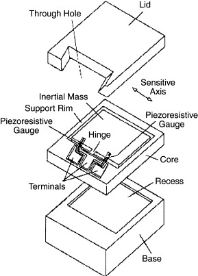
Figure 5.11. Multiple MEMS accelerometer flexure containing diffused and metalized piezoresistive gauges in a Wheatstone bridge configuration.

The advantages of an accelerometer constructed in this manner include a high stiffness, resulting in a high resonant frequency (ω) optimizing its frequency response. This high-resonant frequency is obtained because the square root of the modulus-to-density ratio of silicon, an indicator of dynamic performance, is higher than that for steel. Other desirable byproducts are miniaturization, large signal amplitudes (semiconductor strain gauges have a gauge factor 25 to 50 times that of metal), good linearity, and improved stability. If properly temperature compensated, piezoresistive accelerometers can operate over a temperature range of −65 to +250° F. With current technology, other types of piezoresistive sensors (pressure) operate to temperatures as high as 1000° F.
5.2.3. Capacitive Accelerometers
Capacitive accelerometers are similar in operation to piezoresistive accelerometers, in that they measure a change across a bridge; however, instead of measuring a change in resistance, they measure a change in capacitance. The sensing element consists of two parallel plate capacitors acting in a differential mode. These capacitors operate in a bridge configuration and are dependent on a carrier demodulator circuit or its equivalent to produce an electrical output proportional to acceleration.
Several different types of capacitive elements exist. One type, which utilizes a metal sensing diaphragm and alumina capacitor plates, can be found in Figure 5.12. Two fixed plates sandwich the diaphragm, creating two capacitors, each with an individual fixed plate and each sharing the diaphragm as a movable plate.
Figure 5.12. Capacitive sensor element construction.
When this element is placed in the earth's gravitational field or is accelerated due to vibration on a test structure, the spring-mass experiences a force. This force is proportional to the mass of the spring-mass and is based on Newton's Second Law of Motion. (5.1)
![]() Where
Where
- F = inertial force acting on spring-mass,
- m = distributed mass of spring-mass, and
- a = acceleration experienced by sensing element.
Consequently, the spring-mass deflects linearly according to the spring equation. (5.2)
![]() Where
Where
- X = deflection of spring-mass,
- k = stiffness of spring-mass.
The resulting deflection of the spring-mass causes the distance between the electrodes and the spring-mass to vary. These variations have a direct effect on each of the opposing capacitor gaps according to the following equation:
![]() and (5.3)
and (5.3)
- C = element capacitance,
- AE = surface area of electrode,
- ϵ = permittivity of air, and
- d = distance between spring-mass and electrode.
A built-in electronic circuit is required for proper operation of a capacitive accelerometer. In the simplest sense, the built-in circuit serves two primary functions: (1) allow changes in capacitance to be useful for measuring both static and dynamic events, and (2) convert this change into a useful voltage signal compatible with readout instrumentation.
A representative circuit is shown in Figure 5.13, which graphically depicts operation in the time domain, resulting from static measurand input.
Figure 5.13. Operation of built-in circuit for capacitive accelerometer.
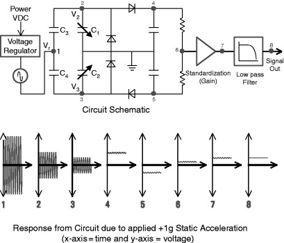
The following explanation starts from the beginning of the circuit and continues through to the output, and describes the operation of the circuit.
To begin, the supply voltage is routed through a voltage regulator, which provides a regulated DC voltage to the circuit. The device assures “clean” power for operating the internal circuitry and fixes the amplitude of a built-in oscillator, which typically operates at >1 MHz. By keeping the amplitude of the oscillator signal constant, the output sensitivity of the device becomes fixed and independent of the supply voltage. Next, the oscillator signal is directed into the capacitance-bridge as indicated by Point 1 in Figure 5.13 (top panel). It then splits and passes through each arm of the bridge, which each act as divider networks. The divider networks cause the oscillator signal to vary in direct proportion to the change in capacitance in C2 and C4. (C2 and C4 electrically represent the mechanical sensing element.) The resulting amplitude-modulated signals appear at Points 2 and 3. Finally, to “demodulate” these signals, they are passed through individual rectification/peak-picking networks at Points 4 and 5, and then summed together at Point 6. The result is an electrical signal proportional to the physical input.
It would be sufficient to complete the circuit at this point; however, additional features are often added to enhance its performance. In this case, a “standardization” amplifier has been included. This is typically used to trim the sensitivity of the device so that it falls within a tighter tolerance. In this example, Point 7 shows how this amplifier can be used to gain the signal by a factor of 2. Finally, there is a low-pass filter, which is used to eliminate any high-frequency ringing or residual affects of the carrier frequency.
If silicon can be chemically machined and processed as the transduction element in a piezoresistive accelerometer, it should similarly be able to be machined and processed into the transduction element for a capacitive accelerometer. In fact, MEMS technology is applicable to capacitive accelerometers. Figure 5.14 illustrates a MEMS variable-capacitance element and its integration into an accelerometer. As with the previously described metal diaphragm accelerometer, the detection of acceleration requires both a pair of capacitive elements and a flexure. The sensing elements experience a change in capacitance attributable to minute deflections resulting from the inertial acceleration force. The single-crystal nature of the silicon, the elimination of mechanical joints, and the ability to chemically machine mechanical stops, result in a transducer with a high overrange capability. As with the previous metal diaphragm accelerometer, damping characteristics can be enhanced over a broad temperature range if a gas is employed for the damping medium as opposed to silicone oil. A series of grooves, coupled with a series of holes in the central mass, squeeze gas through the structure as the mass displaces. The thermal viscosity change of a gas is small relative to that of silicone oil. Capacitive MEMS accelerometers currently operate to hundreds of gravitations and frequencies to 1 kHz. The MEMS technology also results in accelerometer size reduction.
Figure 5.14. MEMS capacitor plates and completed accelerometer with top lid off.

Most capacitive accelerometers contain built-in electronics that inject a signal into the element, complete the bridge, and condition the signal. For most capacitive sensors it is necessary to use only a standard voltage supply or battery to supply appropriate power to the accelerometer.
One of the major benefits of capacitive accelerometers is to measure low-level (less than 2 g), low-frequency (down to DC) acceleration with the capability of withstanding high shock levels, typically 5000 g or greater. Some of the disadvantages of the capacitive accelerometer are a limited high-frequency range, a relatively large phase shift, and higher noise floor than a comparable piezoelectric device.
5.2.4. Servo or (Force Balance) Accelerometers
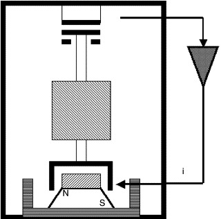
The accelerometers described to date have been all “open-loop” accelerometers. The deflection of the seismic mass, proportional to acceleration, is measured directly using either piezoelectric, piezoresistive, or variable capacitance technology. Associated with this mass displacement is some small, but finite, error due to nonlinearities in the flexure. Servo accelerometers are “closed-loop” devices. They keep internal deflection of the proof mass to an extreme minimum. The mass is maintained in a “balanced” mode virtually eliminating errors due to nonlinearities. The flexural system can be either linear or pendulous (C2 and C4 electrically represent opposite sides of the mechanical sensing element). Electromagnetic forces, proportional to a feedback current, maintain the mass in a null position. As the mass attempts to move, a capacitive sensor typically detects its motion. A servo circuit derives an error signal from this capacitive sensor and sends a current through a coil, generating a torque proportional to acceleration, keeping the mass in a capture or null mode. Servo or “closed-loop” accelerometers can cost up to 10 times what “open-loop accelerometers” cost. They are usually found in ranges of less than 50 g, and their accuracy is great enough to enable them to be used in guidance and navigation systems. For navigation, three axes of servo accelerometers are typically combined with three axes of rate gyros in a thermally stabilized, mechanically isolated package as an inertial measuring unit (IMU). This IMU enables determination of the six degrees of freedom necessary to navigate in space. Figure 5.15 illustrates the operating principal of a servo accelerometer. They measure frequencies to DC (0 Hz) and are not usually sought after for their high-frequency response.
Figure 5.15. Typical servo accelerometer construction.
5.3. Selecting and Specifying Accelerometers
Table 5.1 summarizes the advantages and disadvantages of different type of accelerometers along with some typical applications.
Table 5.1. Comparison of accelerometer types
| Accelerometer type | Advantages | Limitations | Typical applications |
|---|---|---|---|
| IEPE piezoelectric accelerometer | Wide dynamic rangeWide frequency rangeDurable (high shock protection)Powered by low cost constant current sourceFixed outputLess susceptible to EMI and RFInterference can be made very smallLess operator attention, training and installationExpertise requiredHigh impedance circuitry sealed in sensorLong cable driving without noise increaseOperates into many data acquisition devices with built-in constant current inputOperates across slip ringsLower system cost per channel | Limited temperature rangeMax temperature of 175° C (350° F)Low frequency response is fixed within the sensorBuilt-in amplifier is exposed to same test environment as the element of the sensor | Modal analysisNVHEngineNVHFlight testingBody In white testingCryogenicDrop testingGround vibration testing HALT/HASSSeismic testingSqueak and rattleHelmet and sport equipment testingVibration isolation and control |
| Charge piezoelectric accelerometer | High operating temperatures to 700° CWide dynamic rangeWide frequency range(Durable) high shock protectionFlexible outputSimpler design, fewer partsCharge converter electronics is usually at ambient condition, away from test environment | More care/attention is required to install and maintainHigh impedance circuitry must be kept clean and dryCapacitive loading from long cable run results in noise floor increasePowered by charge amp, which can be complicated and expensiveNeed to use special low-noise cable | Jet engineHigh temperatureSteam pipesTurbo machinerySteam turbineExhaustBrake |
| Piezoresistive accelerometer | DC responseSmall size | Lower shock protectionSmaller dynamic range | Crash testingFlight testingShock testing |
| Capacitive accelerometer | DC responseBetter resolution than PR type accelerometer | Frequency rangeAverage resolution | Ride qualityRide simulationBridge testingFlutterAirbag sensorAlarms |
| Servo accelerometer | High sensitivity Highest accuracy for low-level, low-frequency measurements | Limited frequency rangeHigh costFragile, low shock protection. | Guidance ApplicationsRequiring little or no DC baselineDrift |
Table 5.2 lists some of the typical characteristics of different sensors types.
Table 5.2. Typical accelerometer characteristics
| Accelerometer type | Frequency range | Sensitivity | Measurement range | Dynamic range | Size/weight |
|---|---|---|---|---|---|
| IEPE piezoelectric accelerometer | 0.5 Hz to 50,000 Hz | 0.05 mV/g to 10 V/g | 0.000001 g to 100,000 g | ∼120 dB | 0.2 gram to 200 grams |
| Charge piezoelectric accelerometer | 0.5 Hz to 50,000 Hz | 0.01 pC/g to 100 pC/g | 0.00001 g to 100,000 g | ∼110 dB | 0.14 grams to 200+ grams |
| Piezoresistive accelerometer | 0 Hz to 10,000 Hz | 0.0001 mV/g to 10 mV/g | 0.001 g to 100,000 g | ∼80 dB | 1 to 100 grams |
| Capacitive accelerometer | 0 Hz to 1000 Hz | 10 mV/g to 1 V/g | 0.00005 g to 1000 g | ∼90 dB | 10 grams to 100 grams |
| Servo accelerometer | 0 Hz to 100 Hz | 1 V/g to 10 V/g | <0.000001 g to 10 g | >120 dB | >50 grams |
In order to select the most appropriate accelerometer for the application, you should look at a variety of factors. First you need to determine the type of sensor response required. The three basic functional categories of accelerometers are IEPE, charge mode, and DC responding. The first two categories of accelerometers, the IEPE and charge mode type of accelerometers, work best for measuring frequencies starting at 0.5 Hz and above. The IEPE is a popular choice, due to its low-cost, ease of use, and low-impedance characteristics, whereas the charge mode is useful for high-temperature applications. There are advantages of each design.
When looking at uniform acceleration, as may be required for tilt measurement or extremely low-frequency measurements below 1 Hz, capacitive or piezoresistive accelerometers are a better choice. Both accelerometer types have been designed to achieve true 0 Hz (DC) responses. These sensors may contain built-in signal conditioning electronics and a voltage regulator, allowing them to be powered from a 5–30-VDC source. Some manufacturers offer an offset adjustment, which serves to null any DC voltage offset inherent to the sensor. Capacitive accelerometers are generally able to measure smaller acceleration levels.
The most basic criteria used to narrow the search, once the functionality category or response type of accelerometer has been decided, includes sensitivity, amplitude, frequency range, and temperature range. Sensitivity for shock and vibration accelerometers is usually specified in millivolts per gravitation (mV/g) or picocoulombs per gravitation (pC/g). This sensitivity specification is inversely proportional to the maximum amplitude that can be measured (gravitational peak range). Thus, more sensitive sensors will have lower maximum measurable peak amplitude ranges. The minimum and maximum frequency range that is going to be measured will also provide valuable information required for the selection process. Another important factor for accelerometer selection is the temperature range. Consideration should be given not only to the temperatures that the sensor will be exposed to but also the temperature that the accelerometer will be stored at. High-temperature special designs are available for applications that require that specification.
Every sensor has inherent characteristics, which cause noise. The broadband resolution is the minimal amount of amplitude required for a signal to be detected over the specified band. If you are looking at measuring extremely low amplitude, as in seismic applications, spectral noise at low frequency may be more relevant.
Physical characteristics can be very important in certain applications. Consideration should be given to the size and weight of the accelerometer. It is undesirable to place a large or heavy accelerometer on a small or lightweight structure. This is called mass loading. Mass loading will affect the accuracy of the results and skew the data. The area that is available for the accelerometer installation may dictate the accelerometer selection. There are triaxial accelerometers, which can be utilized to simultaneously measure acceleration in three orthogonal directions. Older designs required three separate accelerometers to accomplish the same result and thus add weight and require additional space.
Consideration should be given to the environment that the accelerometer will be exposed to. Hermetically sealed designs are available for applications that will be exposed to contaminants, moisture, or excessive humidity levels. Connector alternatives are available. Sensors can come with side connections or top connections to ease cable routing. Some models offer an integrated cable. Sensors with field-repairable cabling can prove to be very valuable in rough environments.
Accelerometer mounting may have an effect on the selection process. Most manufacturers offer a variety of mounting alternatives. Accelerometers can be stud mounted, adhesively mounted, or magnetically mounted. Stud mounting provides the best stiffness and highest degree of accuracy, while adhesive mounts and magnetic mounting methods offer flexibility and quick removal options.
There are a wide variety of accelerometers to choose from. More than one will work for most applications. In order to select the most appropriate accelerometer, the best approach is to contact an accelerometer manufacturer and discuss the application. Manufacturers have trained application engineers who can assist you in selecting the sensor that will work best for your application.
5.4. Applicable Standards
In order to verify accelerometer performance, sensor manufacturers will test various characteristics of the sensor. This calibration procedure serves to help both the manufacturer and the end user. The end user will obtain a calibration certificate to confirm the accelerometer's exact performance characteristics. The manufacturer uses this calibration procedure for traceability and to determine whether the product meets specifications and should be shipped or rejected. It can be viewed as a built-in quality control function. It provides a sense of security or confidence for both the manufacturer and the customer.
However, be aware that all calibrations are not equal. Some calibration reports may include terms such as nominal or typical, or even lack traceability or accredited stamps of approval. With the use of words like nominal or typical, the manufacturer does not have to meet a specific tolerance on those specifications. This helps the manufacturer ship more products and reduce scrap, since fewer measured specifications means fewer rejections. While this provides additional profit for a manufacturer, it is not a benefit to the end customer. Customers have to look beyond the shiny paper and cute graphics, to make sure of the completeness of the actual measured data contained in each manufacturer's calibration certificate.
Due to the inconsistency of different manufacturer's calibration techniques and external calibration services, test engineers came up with standards to improve the quality of the product and certification that they receive. MIL-STD-45662 was created to define in detail the calibration system, process, and components used in testing, along with the traceability of the product supplied to the government. The American National Standards Institute (ANSI) came up with its own version of specifications labeled ANSI/NCSL Z540-1-1994. This ANSI standard along with the International Organization for Standards (ISO) 10012-1, have been approved by the military as alternatives for the canceled MIL standard. The ANSI Z540-1 and ISO 17025 require that uncertainty analyses for verifying the measurement process be documented and defined. Although the ANSI and ISO specifications are more common, the MIL specification, although canceled in 1995, is still referenced on occasion.
Years ago, the National Bureau of Standards (NBS) recognized the inconsistencies in calibration reports and techniques and developed a program for manufacturers to gain credibility and consistency. The National Institute of Standards and Technology (NIST) replaced the NBS in 1988, as the standard for accelerometer calibration approval. International compliance can be accredited by other sources. Physikalisch-Technische Bundesanstalt (PTB) in Germany and United Kingdom Accreditation Service (AKAS) in Britain are popular organizations that supply this service. Manufacturers can send in their “Reference Sensors” that they utilize in back-to-back testing to NIST or PTB in order to obtain certification from NIST or PTB (or both) to gain credibility and get the stamp of approval of these organizations.
The International Organization for Standardization initiated its own set of standards. The initial ISO standards concentrated on the documentation aspects of calibrating sensors. ISO 10012-1 addressed the MIL-45662 specifications, which added accuracy standards to the documentation. ISO17025 concentrated on traceability and accountability for the calibration work performed by the organization or laboratory, for a more complete set of standards. ISO standards that accelerometer customers should look for include:
- ISO 9001 Quality systems for assurance in design, development and production
- ISO 10012-1 Standards for measurement in management systems
- ISO 16063-21 Methods for calibration of vibration and shock transducers
- ISO 17025 General requirements for competence of testing and calibration laboratories
- RP-DTE011.1 Shock and Vibration Transducer Selection, Institute of Environmental Sciences
Today, end users can purchase with confidence sensors that have traceable certifications that comply with the standards set by the NIST, PTB, ANSI, ISO, and A2LA, provided that the data on the calibration is complete. The better manufacturers will reference most, if not all, of these organizations.
5.5. Interfacing and Designs
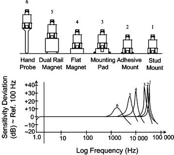
One consideration in dealing with accelerometer mounting is the effect the mounting technique has on the accuracy of the usable frequency response. The accelerometer's operating frequency range is determined, in most cases, by securely stud mounting the test sensor directly to the reference standard accelerometer. The direct coupling, stud mounted to a very smooth surface, generally yields the highest mechanical resonant frequency and, therefore, the broadest usable frequency range. The addition of any mass to the accelerometer, such as an adhesive or magnetic mounting base, lowers the resonant frequency of the sensing system and may affect the accuracy and limits of the accelerometer's usable frequency range. Also, compliant materials, such as a rubber interface pad, can create a mechanical filtering effect by isolating and damping high-frequency transmissibility. A summary of the mounting techniques is provided next.
5.5.1. Stud Mounting
For permanent installations, where a very secure attachment of the accelerometer to the test structure is preferred, stud mounting is recommended. First, grind or machine on the test object a smooth, flat area at least the size of the sensor base, according to the manufacturer's specifications. For the best measurement results, especially at high frequencies, it is important to prepare a smooth and flat, machined surface where the accelerometer is to be attached. The mounting hole must also be drilled and tapped to the accelerometer manufacturer's specifications. Misalignment or incorrect threads can cause not only erroneous data, but can damage the accelerometer. The manufacturer's torque recommendation should always be used, measured with a calibrated torque wrench.
5.5.2. Adhesive Mounting
Occasionally, mounting by stud or screw is impractical. For such cases, adhesive mounting offers an alternative mounting method. The use of separate adhesive mounting bases is recommended to prevent the adhesive from damaging the accelerometer base or clogging the mounting threads. (Miniature accelerometers are provided with the integral stud removed to form a flat base.) Most adhesive mounting bases provide electrical isolation, which eliminates potential noise pickup and ground loop problems. The type of adhesive recommended depends on the particular application. Wax offers a very convenient, easily removable approach for room temperature use. Two-part epoxies offer high stiffness, which maintains high-frequency response and a permanent mount.
5.5.3. Magnetic Mounting
Magnetic mounting bases offer a very convenient, temporary attachment to magnetic surfaces. Magnets offering high pull strengths provide best high-frequency response. Wedged dual-rail magnetic bases are generally used for installations on curved surfaces, such as motor and compressor housings and pipes. However, dual-rail magnets usually significantly decrease the operational frequency range of an accelerometer. For best results, the magnetic base should be attached to a smooth, flat surface.
5.5.4. Probe Tips
Handheld vibration probes or probe tips on accelerometers are useful when other mounting techniques are impractical and for evaluating the relative vibration characteristics of a structure to determine the best location for installing the accelerometer. Probes are not recommended for general measurement applications due to a variety of inconsistencies associated with their use. Orientation and amount of hand pressure applied create variables, which affect the measurement accuracy. This method is generally used only for frequencies less than 1000 Hz.
Figure 5.16 summarizes the changes in the frequency response of a typical sensor using the various mounting methods previously discussed.
Figure 5.16. Relative frequency response of different accelerometer mounting techniques.
5.5.5. Ground Isolation, Ground Noise, and Ground Loops
When installing accelerometers onto electrically conductive surfaces, a potential exists for ground noise pickup. Noise from other electrical equipment and machines that are grounded to the structure, such as motors, pumps, and generators, can enter the ground path of the measurement signal through the base of a standard accelerometer. When the sensor is grounded at a different electrical potential than the signal conditioning and readout equipment, ground loops can occur. This phenomenon usually results in current flow at the line power frequency (and harmonics thereof), potential erroneous data, and signal drift. Under such conditions, it is advisable to electrically isolate or “float” the accelerometer from the test structure. This can be accomplished in several ways. Most accelerometers can be provided with an integral ground isolation base. Some standard models may already include this feature, while others offer it as an option. The use of insulating adhesive mounting bases, isolation mounting studs, isolation bases, and other insulating materials, such as paper beneath a magnetic base, are effective ground isolation techniques. Be aware that the additional ground-isolating hardware can reduce the upper frequency limits of the accelerometer.
5.5.6. Cables and Connections
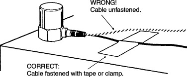
Cables should be securely fastened to the mounting structure with a clamp, tape, or other adhesive to minimize cable whip and connector strain. Cable whip can introduce noise, especially in high-impedance signal paths. This phenomenon is known as the triboelectric effect. Also, cable strain near either electrical connector can lead to intermittent or broken connections and loss of data (Figure 5.17).
Figure 5.17. Cable strain relief of accelerometers.
To protect against potential moisture and dirt contamination, use RTV sealant or heat-shrinkable tubing on cable connections. O-rings with heat shrink tubing have proven to be an effective seal for protecting electrical connections for short-term underwater use. RTV sealant is generally only used to protect the electrical connection against chemical splash or mist.
5.5.7. Latest and Future Developments
Manufacturers are continually trying to develop sensor packages that are smaller and lighter in weight than previous models. This minimizes mass loading effects and provides the user with the ability to test smaller and lighter components. Triaxial designs are becoming more popular and manufacturers have been designing improved versions of this product. A triaxial accelerometer can take the place of three single-axis accelerometers. The triaxial accelerometer can measure vibration in three orthogonal directions simultaneously, in one small lightweight convenient package, with a single-cable assembly.
One of the emerging standards for accelerometers and other sensor types is the IEEE 1451 Smart Transducer Interface. This standard defines the hardware and communication protocol for interfacing a sensor onto a network. IEEE P1451.4 defines the architecture and protocol for compiling and addressing nonvolatile memory that is imbedded within an analog measurement sensor. Accelerometers with this built-in digital memory chip are referred to as TEDS accelerometers. TEDS is an acronym for transducer electronic data sheet. TEDS allows the user to identify specific sensors within a large channel group or determine output from different sensors at multiple locations very easily. TEDS can provide the user with technical information on the particular sensor. For instance, model number, serial number, calibration date, and some technical specifications can be retrieved from each individual sensor that is TEDS compliant. Sensitivity specifications from calibration reports can be read through the TEDS and compensated for, so that the data acquisition system or readout can generate more accurate information.
With the need for high-temperature models, manufacturers have been concentrating on developing new designs that will make accurate measurements in the most severe environments. End users have had requirements for sensors that can operate in colder and hotter temperatures than the standard accelerometers are specified for. As long as customers come up with new and unique applications, manufacturers will try to come up with products to satisfy their requirements.
The most exciting development that is likely to occur over the next decade is placing an analog-to-digital converter (ADC) directly inside the accelerometer. This will enable the accelerometer to provide digital output. Accelerometers enhanced with this type of output will be able to have features such as 24-bit ADC, wireless transmission, built-in signal processing, and the ability to be accessed over the World Wide Web.
5.6. Machinery Vibration Monitoring Sensors
5.6.1. Introduction
The ears and hands are very subjective when sensing vibrations. The days of judging a machine's health by sound and touch (or listening to a screwdriver placed against the machine) have quickly transitioned to a more scientific approach, allowing data trending and early prediction of machinery failure.
In order to make objective, informed decisions, most measurement engineers prefer to have consistent, trendable data that can be regularly referred to. Machinery vibration sensors, along with a readout instrument, can provide this objective information, allowing for a more precise assessment of machinery health.
Due to the piezoelectric accelerometer's wide frequency response, it is an excellent sensor to replace human subjectivity in most machinery health monitoring. In addition, permanent mounting of these sensors provides continuous monitoring or shutdown functions for critical machinery. This allows plant and production management to be predictive in their maintenance strategy. The result is cost-effective, scheduled downtime to repair equipment as opposed to a reactive approach toward maintenance, which often involves expensive loss of production and repairs. In the future, it is expected that a greater percentage of machines will continue to be monitored for earlier prediction of failures. This will allow maintenance personnel to focus on the smaller percentage of machines actually having problems as opposed to manually monitoring and wasting expensive labor on healthy machinery.
Some of the key applications and industries in which machinery vibration sensors are utilized are as follows:
- Aluminum plants
- Automotive manufacturing
- Balancing
- Bearing analysis and diagnostics
- Bearing vibration monitoring
- Bridges and civil structures
- Coal processing
- Cold-forming operations
- Concrete processing plants
- Condition-based monitoring
- Compressors
- Cooling towers
- Crushing operations
- Diagnostics of machinery
- Engines
- Floor vibration monitoring
- Food, dairy, and beverage
- Foundations
- Gearbox monitoring
- Geological exploration
- Heavy equipment and machinery
- Helicopters
- Hull-vibration monitoring
- HVAC equipment
- Impact measurements
- Impulse response
- Machine tools
- Machinery-condition monitoring
- Machinery frames
- Machinery-mount monitoring
- Machinery-vibration monitoring
- Manufacturing
- Mining
- Modal analysis
- Motor vibration
- Off-road equipment
- Paper-machinery monitoring
- Petrochemical
- Pharmaceutical
- Power generation
- Predictive maintenance
- Printing
- Pulp and paper
- Pumps
- Quality control
- Seismic monitoring
- Shipboard machinery
- Shock measurements
- Shredding operations
- Site-vibration surveys
- Slurry pulsation monitoring
- Spindle vibration and imbalance
- Squeak and rattle detection
- Steel and metals
- Structure-borne noise
- Structural testing
- Submersible pumps
- Transportation equipment
- Turbines
- Turbomachinery
- Underwater pumps
- Vibrating feeders
- Vibration control
- Vibration isolation
- Water treatment plants
- Wastewater treatment plants
The typical faults that machinery-vibration sensors are able to detect, along with their approximate percent of occurrence, are shown in Table 5.3.
Table 5.3. Typical faults detected by machinery-vibration sensors
| Imbalance | 40% |
| Misalignment | 30% |
| Resonance | 20% |
| Belts | 30% |
| Bearings | 10% |
| Motor | 8% |
| Pump | 5% |
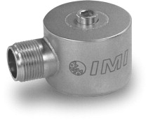
Accelerometers are the most common machinery-vibration sensor used today. Applications for accelerometers in the industrial sector are primarily focused on extending service life of machinery by predicting failures and allowing maintenance to be conducted in a planned manner. By doing so, operators can make more intelligent decisions about spare parts purchases and keep critical equipment up and running longer and faster to increase product output and profitability. Accelerometers are ideal for small- to medium-sized machines with rolling element bearings, where the casing and bearings move with the rotor. In this case, an accelerometer (sometimes referred to as a seismic transducer) on the bearing housing will also be a good indicator of shaft motion. They are convenient to use and easily attach directly to the outside of the bearing housing. (These can still be used on journal bearing machines on the outside casings, but the motion will be smaller on the outside casing because of the mass of the casing and the reduced transmissibility through the fluid film.)
Technically speaking, accelerometers are transducers that are designed to produce an electrical output signal that is proportional to applied acceleration. Several sensing technologies are utilized to construct accelerometers, including resistive (foil or silicon strain gauges), capacitive, and piezoelectric. Resistive and capacitive types possess the ability to measure constant acceleration, such as that of earth's gravity, and are generally only used for measuring very low-frequency vibration, such as that encountered with massive, slow-speed rollers. On the other hand, piezoelectric types possess an extremely wide frequency range and are suited to accurately measure most other types of vibration. They are ideal for machinery vibration monitoring and are recommended for nearly every industrial vibration application on rotating machinery.
Piezoelectric accelerometers are generally durable, protected from contamination, impervious to extraneous noise influences, and are easy to implement. Accelerometers that are designed with these features are classified as industrial accelerometers and are normally suitable for use in rigorous industrial, field, or submersible environments.
5.6.2. Technology Fundamentals
Piezoelectric accelerometers rely on the piezoelectric effect. This basically means that the internal sensing material will provide an electrical charge when squeezed or strained.
There are several methods used to stress the piezoelectric material. (All of these methods utilize a seismic mass attached to the sensing material and rely on Newton's Second Law: Force = Mass × Acceleration.) These methods are categorized in the following terms that define the geometry of the sensing element—compression, flexural, and shear. Each has advantages and disadvantages; however, for best overall performance in industrial machinery vibration applications, leading manufacturers utilize, almost exclusively, the shear structured geometry for its piezoelectric industrial accelerometers. (See Figure 5.18.)
Figure 5.18. Photo and cross-section diagram of shear accelerometer.

The shear sensing element design exhibits compact construction, good stiffness, good durability, and high resonant frequency. This design is less susceptible to extraneous inputs from base strain and thermal transients. Older compression geometries have been superseded by the shear type for industrial applications, primarily due to the thermal transient induced base strain error susceptibility of compression designs, particularly at low frequencies. This low-frequency error, or drift, causes what is commonly termed ski slope error, which becomes evident when acceleration signals are integrated into velocity signals. Regrettably, some manufacturers still rely on this aged design in their product line. Volume production of shear style accelerometers has also reduced their cost to a level acceptable to the industrial market, further justifying their use.
Regardless of the sensing element design, as the piezoelectric material is stressed, charged ions accumulate at their surfaces. Electrodes that are in intimate contact with the crystals collect these ions, which result in an electrical signal. The signal is then transmitted via a small wire to a signal conditioning circuit that is positioned within the accelerometer's housing. The signal conditioning circuit serves to convert the difficult-to-use, high-impedance charge signal from the crystal into a low-impedance voltage signal that can be transmitted outside of the accelerometer housing, over a relatively long distance, without degradation. This low-impedance voltage signal can then be interrogated by data collection equipment, displayed on an oscilloscope, stored on a recording instrument, or analyzed with a data acquisition system or FFT analyzer. This type of accelerometer is generically termed an IEPE accelerometer for Integrated electronic piezoelectric, or also commonly referred to as an ICP® (integrated circuit piezoelectric) accelerometer, which is a registered trademark of PCB Group, Inc.
Additional circuitry can be added to enhance or tune the output signal for specific purposes. Such enhancements include filtering, rms conversion, 4–20-mA transmitters, integrators, and TEDS (transducer electronic data sheet—an on-board, addressable memory with stored, self-identifying information).
To properly operate, sensors with built-in electronics require a constant current power source. Normally, this constant current power supply is built into the industrial readout equipment (data collector or online monitor). If it is not included, sensor manufacturers offer a variety of different power supplies.
While the fundamental technology associated with accelerometers is very similar, the specific design of the sensor is critical. Industrial accelerometers have to endure severe environments and tough operating conditions. In order to achieve these requirements, there are several design and construction characteristics to be aware of. These design criteria include
- Welded, stainless steel housing This proven, corrosive-resistant material stands up well against dirt, oil, moisture, and harsh chemicals. Stainless steel is also nonmagnetic, which minimizes errors induced when used in the vicinity of electric motors and other sources of electromagnetic interference. For durability, all mating housing parts are precision laser welded. No epoxies are used that can eventually fatigue or cause leaks.
- Internal Faraday shield Accelerometers that utilize an internal electrical shield to guard against radio frequency interference (RFI), electromagnetic interference (EMI), and other extraneous noise influences. The result is an electrically case-isolated sensing element that is insulated from ground, which also ensures that there will not be any ground loops in the measurement system that can cause signal drift, noise, and other hard-to-trace electrical problems.
- Durable, military-style electrical connectors or sealed, integral cables It is highly recommended to use electrical connectors that offer a true hermetic seal with glass-to-metal fusing of connector pins and shells. All connectors should be laser welded to the sensor housing. Sensors with integral cables incorporate hermetic feedthrough pins and high-pressure, injection-molded sealing of the cable to a metallic shell that is laser welded to the sensor housing. Integral polyurethane jacketed cables offer 750 psi submersibility along with excellent pull strength and strain relief characteristics.
- Rugged cables Interconnect cables should utilize shielded, twisted conductor pairs and an outer jacket material that will survive exposure to most industrial media or excessive temperatures present in the environment in which it will be used. Stainless steel, armored cables are recommended for installations where machined debris or chips may damage cable jackets or where cables have the potential of being stepped on or pinched. Electrical connectors for cables are offered in a variety of styles and configurations to suit the application. Take care to note the temperature rating of the connector and material of construction. Environmentally sealed cable connectors provide a boot to protect the integrity of the connection in outdoor installations or during wash-down episodes.
5.6.3. Accelerometer Types
5.6.3.1. Low-Cost, Industrial ICP Accelerometers for Permanent Installation
Low-cost, industrial ICP accelerometers are recommended for permanent installation onto machinery to satisfy vibration trending requirements in predictive maintenance and condition monitoring applications. In addition to sound design and high-volume manufacturing techniques, lower cost is achieved by relaxing the tolerance on sensitivity from unit to unit and by calibrating at only one reference frequency point, typically 100 Hz. Measurement accuracy is compromised only if the sensor's nominal sensitivity is used. If the provided single-point sensitivity is used, accuracy is very good.
Since low-cost sensors carry a wider sensitivity tolerance, the actual measurement obtained using the nominal sensitivity value may not be as quantitatively accurate as could be achieved if one uses the supplied reference sensitivity value. This disparity, however, may be irrelevant since when trending, the user is primarily interested in recognizing changes in the overall measured vibration amplitude or frequency signature of the machinery. When comparing against previously acquired data obtained with the same sensor in the same location, the excellent repeatability of these piezoelectric vibration sensors becomes the vital attribute for successful trending requirements. The user benefits by being able to employ a lower-cost sensor, which in turn makes monitoring additional measurement points a more attractive undertaking.
5.6.3.2. Low-Frequency Industrial ICP Accelerometers
Low-frequency accelerometers are generally designed for use on large slow-rotating equipment. Applications include
- Vibration measurements on slow-rotating machinery
- Paper machine rolls
- Large structures and machine foundations
- Large fans and air handling equipment
- Cooling towers
- Buildings, bridges, foundations, and floors
Low-acceleration levels go hand in hand with low-frequency vibration measurements. For this reason, these accelerometers combine extended low-frequency response with high-output sensitivity in order to obtain the desired amplitude resolution characteristics and strong output signal levels necessary for conducting low-frequency vibration measurements and analysis.
The most sensitive low-frequency accelerometers are known as seismic accelerometers. These models are larger in size to accommodate their larger seismic, internal masses, which are necessary to generate a stronger output signal. These sensors have a limited amplitude range, which renders them unsuitable for many general-purpose industrial vibration measurement applications. However, when measuring the vibration of slow, rotating machinery, buildings, bridges, and large structures, these low-frequency, low-noise accelerometers will provide the characteristics required for successful results.
All low-frequency industrial accelerometers benefit from the same advantages offered by general-purpose industrial accelerometers, including rugged, laser-welded, stainless steel housing with the ability to endure dirty, wet, or harsh environments; hermetically sealed military connector or sealed integral cable; and a low-noise, low-impedance, voltage output signal with long-distance signal transmission capability.
5.6.3.3. High-Frequency Industrial ICP Accelerometers
High-frequency accelerometers are generally used for high-speed rotating machinery. Applications include
- Vibration measurements on high-speed rotating machinery
- Gear mesh studies and diagnostics
- Bearing monitoring
- Small mechanisms
- High-speed spindles
Successful vibration measurements begin with sensors that have adequate capabilities for the requirement. If the sensor's frequency response characteristics are inadequate, the user risks corrupted or insufficient data to achieve a proper analysis and diagnosis. For vibration monitoring, testing, and frequency analysis of high-speed rotating machinery, spindles, and gear mesh, it is imperative to utilize a sensor with a sufficient high-frequency range to accurately capture the vibration signals within the bandwidth of interest. Miniature-sized units are also suitable for vibration measurements on small mechanisms where sensor size and weight become important factors.
5.6.3.4. 4–20-mA Vibration Sensing Transmitters
These sensors are accelerometers that have been configured to have a loop-powered, 4–20-mA output. Generally, vibration sensing transmitters provide output signals that are representative of the overall vibration. (Typically, an internal integrator is included so that the output is in velocity, such as in./s rms or mm/s pk.) This vibration signal may be interfaced with many types of commercially available current-loop monitoring equipment, such as recorders, alarms, programmable logic controllers (PLCs), and digital control systems (DCSs).
The vibration-sensing transmitters capitalize on the use of existing process control equipment and human/machine interface (HMI) software for monitoring machinery vibration and alarming of excessive vibration levels. This allows the operator to monitor machinery using the existing process control system as opposed to having to purchase specific vibration monitory software. This practice offers the ability to continuously monitor machinery and provide an early warning detection of impending failure. With this approach, existing process control technicians can monitor the vibration levels while skilled vibration specialists are called upon only in the event that the vibration signal warrants more detailed signal analysis. It is envisioned that someday machinery vibration measurements will be monitored in process facilities via 4–20-mA transmitters as widely as pressure, temperature, flow, and load are currently done so today.
A choice of velocity or acceleration measurement signals are offered with a variety of amplitude and frequency ranges to suit the particular application. Most models also feature an optional analog output signal connection (raw vibration option) for conducting frequency analysis and machinery diagnostics.
5.6.3.5. DC Response, Industrial Capacitive Accelerometers—Applications
DC response accelerometers are generally only used on very large, slow-rotating equipment or on extremely large civil structures. Applications include
- Paper machine rolls
- Large structures and machine foundations
- Cooling towers
- Buildings, bridges, foundations, and floors
Unlike piezoelectric accelerometers that have a low-frequency limit, industrial capacitive accelerometers are capable of measuring to true DC, or 0 Hz.
Capacitive accelerometers utilize two opposed plate capacitors that share a common flexible plate in the middle. As the flexible plate responds to acceleration, differential output signals from the two capacitors are created. These signals are conditioned to reject common mode noise and combined to provide a standardized output sensitivity. Built-in voltage regulation and optional low-power versions permit operation from a wide variety of DC power sources. The result is a sensor that is easy to implement and delivers a high-integrity, low-noise output signal.
DC response, industrial capacitive accelerometers offer many of the same advantages as general-purpose industrial accelerometers, including rugged, laser-welded, stainless steel housing with the ability to endure dirty, wet, or harsh environments; hermetically sealed military connector or sealed integral cable; and a low-noise, low-impedance voltage output signal with long-distance signal transmission capability.
5.6.4. Selecting Industrial Accelerometers
There will usually be several accelerometer models that meet the required measurement parameters, so the question naturally arises, Which should be used? By answering the following questions as accurately as possible, the user will be able to determine a set of key specifications required for the accelerometer.
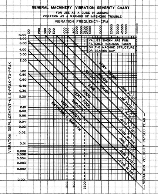
- Measurement range/sensitivity Determine the maximum peak vibration amplitude that will be measured and select a sensor with an appropriate measurement
range. For a typical accelerometer, the maximum measurement range is equal to ±5V divided by the sensitivity. For example,
if the sensitivity is 100 mV/g then the measurement range is (5V/0.1 V/g) = ±50 g. Allow some overhead in case the vibration
is a little higher than expected. The vibration severity chart shown in Figure 5.19 may help when determine the expected measurement range.
Figure 5.19. Vibration severity chart.
- Frequency range Determine the lowest and highest frequencies to be analyzed. If you are not sure what the upper frequency range should be,
use Table 5.4, showing recommended frequency spans as a guideline.
- Select an accelerometer that has a frequency range that encompasses both the low and high frequencies of interest. In some rare cases, it may not be possible to measure the entire range of interest with a single accelerometer.
- High-Frequency Caution Many machines, such as pumps, compressors, and some spindles, generate high frequencies beyond the measurement range of interest. Even though these vibrations are out of the range of interest, the accelerometer is still excited by them. Since high frequencies are usually accompanied by high accelerations, they will often drive higher-sensitivity accelerometers (100- and 500-mV/g models) into saturation causing erroneous readings. If a significant high-frequency vibration is suspected or if saturation occurs, a lower-sensitivity (typically 10 or 50 mV/g) accelerometer should be used. For some applications, higher-sensitivity accelerometers are available with built-in low-pass filters. These sensors filter out the unwanted high-frequency signals and thus provide better amplitude resolution at the frequencies of interest.
- To determine if you have a condition that will overdrive (saturate) the accelerometer, look at the raw vibration signal in the time domain on a data collector, spectrum analyzer, or oscilloscope. Set the analyzer for a range greater than the maximum rated output of the accelerometer. If the amplitude exceeds the maximum rated measurement range of the accelerometer (typically 5V or 50 g for a 100 mV/g unit), then a lower-sensitivity sensor should be selected. If the higher-sensitivity sensor is used, clipping of the signal and saturation of the electronics is likely to occur. This will result in false harmonics, “ski slope” as well as many other serious measurement errors.
Table 5.4. Frequency range guidelines (Eshleman 1999)
Notes: rpm = Revolutions per minute GMF = Gear mesh frequency BPFI = Ball pass frequency inner race VP = Vane pass frequency LF = Line frequency (60 Hz in the United States) BP = Blade pass frequencyRecommended frequency spans (upper frequency) Shaft vibration 10 × rpm Gearbox 3 × GMF Rolling element bearings 10 × BPFI Pumps 3 × VP Motors/generators 3 × (2 × LF) Fans 3 × BP Sleeve bearings 10 × RPM - Broadband resolution (noise) Determine the amplitude resolution that is required. This will be the smaller of either the lowest vibration level or the smallest change in amplitude that must be measured. Select a sensor that has a broadband resolution value equal to or less than this value. For example, if measuring a spindle with 0.001-g minimum amplitude, choose an accelerometer with a resolution better than 1 mg. If the known vibration levels are in velocity (in./s) or displacement (mils), convert the amplitudes to acceleration (g) at the primary frequencies. Note: The lower the resolution value, the better the resolution is. Generally, ceramic sensing elements have better resolutions (less noise) than quartz-based sensors.
- Temperature range Determine the highest and lowest temperatures that the sensor will be subjected to and verify that they are within the specified
range for the sensor.
- Temperature transients In environments where the accelerometer will be subjected to significant temperature transients, quartz sensors may achieve better performance than ceramic. Ceramic sensing elements are subject to the pyroelectric effect, which can cause erroneous outputs with changes in temperature. These outputs typically occur as drift (very low frequency) and usually cause significant “ski slope” when the signal is integrated and displayed in the velocity spectrum.
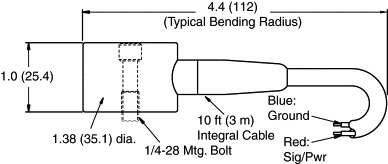
- Size In many cases, the style of the sensor used can be restricted by the amount of space that is available on a machine to mount
the sensor. There are typically two parameters that govern which sensors will fit, the footprint and the clearance. The footprint
is the area covered by the base of the sensor. The clearance is the height above the surface required to fit the sensor and
cable. As an example, a top exit sensor (Figure 5.20) will require more clearance than a side exit (Figure 5.21).
- Orientation Cable orientation is another consideration. Ring-style, side exit models can be oriented 360°, however, in some very tight
spaces, even these may be difficult to install. For example, there may not be enough height clearance to fit a wrench to tighten
the unit. In that case, a swivel mount style accelerometer (Figure 5.22) may be required.
Figure 5.22. “Swivel mount” accelerometer.
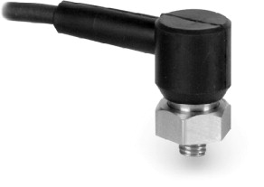
Figure 5.20. “Top exit” accelerometer (requires more clearance).

Figure 5.21. “Side exit” accelerometer (requires less clearance).
- Orientation Cable orientation is another consideration. Ring-style, side exit models can be oriented 360°, however, in some very tight
spaces, even these may be difficult to install. For example, there may not be enough height clearance to fit a wrench to tighten
the unit. In that case, a swivel mount style accelerometer (Figure 5.22) may be required.
- Duty (accuracy, sensitivity tolerance, and safety) The duty refers to the type of use that a sensor will see. Most typical predictive maintenance applications are either in
a walk-around application, as with a portable data collector, or permanently mounted to a particular machine. In permanent
mount applications, the sensor may terminate at a junction box where measurements are taken with a portable data collector
or tied to an online monitoring system. Usually, 4–20-mA output sensors would be tied to existing plant systems such as a
PLC.
- Sensitivity tolerance (absolute accuracy) Sensitivity tolerance is the maximum deviation that the actual sensitivity of an accelerometer can vary from its published nominal sensitivity and still be within specification. Most manufacturers offer accelerometers with ±5%, ±10%, ±15%, and ±20% tolerances on sensitivity. Thus, a nominal 100-mV/g sensor with a ±5% tolerance could have an actual sensitivity between 95 and 105 mV/g. A ±20% tolerance unit could vary between 80 and 120 mV/g. If the nominal sensitivity is used to convert the actual data to engineering units (e.g., entered into the data collection device), then a looser tolerance sensor will be less accurate, in general, than a tighter tolerance model. However, if the actual calibration value that is supplied with the sensor is used, then both readings will be equally accurate. In applications where absolute accuracy is important (e.g., in acceptance testing) then either higher-tolerance sensors or the actual calibration factors should be used.
- Lower-tolerance sensors are typically provided with a single-point calibration rather than full calibration. This, coupled with the looser tolerance, helps keep costs down and allows them to be offered at a much more economical price. Normally, these sensors are selected for permanent mount applications where larger numbers of accelerometers are needed.
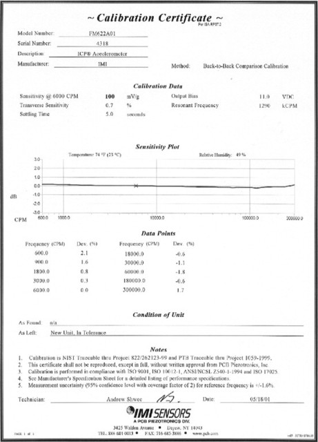
- Calibration interval Due to the inherent stability of quartz, accelerometers with quartz sensing elements have a longer recommended calibration
interval than do ceramic sensors. The recommended time between calibrations is one year for ceramic sensors and five years
for quartz. As a practical matter, however, it may not be possible to send ceramic sensors in for yearly recalibration. As
long as the sensor is permanently mounted and not going through severe thermal transients on a regular basis, its sensitivity
should remain fairly stable. However, if it is seeing repeated shocks (as with magnetic mounting in a walk-around system)
or severe thermal transients, it is highly recommended that the sensor be recalibrated yearly. One advantage of quartz sensors
is its long-term stability even in high shock and thermally transient environments. A typical calibration certificate is shown
in Figure 5.23.
Figure 5.23. Typical accelerometer calibration certificate.
- Accessibility, safety, and production considerations Monitoring locations on machines are often inaccessible due to shrouds, safety requirements, space constraints, or other physical obstacles. Additionally, they may be in hazardous areas or have limited access due to pressing production schedules. In cases like these, permanent mount accelerometers should be selected. This provides a fast, easy, and safe way to collect vibration data.
- Cabling It is recommended, in most cases, that connector style accelerometers be used rather than ones with integral cable. Cables
are very susceptible to damage and are usually the source of most sensor problems. Therefore, it is much easier and more cost
effective to replace a cable rather then the entire accelerometer/cable assembly. It is important to recognize that cables
are vulnerable to damage and should be installed out of harm's way. Having spare cables on hand is recommended as they can
help troubleshoot system performance and keep a measurement system up and running in the event of a cable failure.
- Integral cable models are recommended in submersible applications where sealing is of prime importance. Armored cable (Figure 5.24) is recommended in applications where sharp objects could cut the cable, such as metal chips in machining operations.
Figure 5.24. Armor cabling.

- Integral cable models are recommended in submersible applications where sealing is of prime importance. Armored cable (Figure 5.24) is recommended in applications where sharp objects could cut the cable, such as metal chips in machining operations.
- Intrinsically safe/explosion proof Many sensor models are approved for use in hazardous areas when used with a properly installed intrinsic safety (I.S.) barrier or enclosure. Approval authorities include Canadian Standards Association, CENELEC, Factory Mutual, and Mine Safety Administration.
- Mounting considerations There are several methods for securing vibration sensors to machinery. These include stud mounting, adhesive mounting, and magnetic mounting. Additionally, the use of a probe tip may be useful for very inaccessible measurement points, for locations where physical attachment of a sensor is just not practical, or for determining installation locations where vibration is most prevalent.
Each mounting method will affect the frequency response attainable by the vibration sensor since the mounted resonant frequency of the sensor/hardware assembly will be dependent upon its mass and stiffness. Figure 5.25 depicts how resonant frequency is affected by each mounting technique.
Figure 5.25. Effect of mounting technique on frequency response.
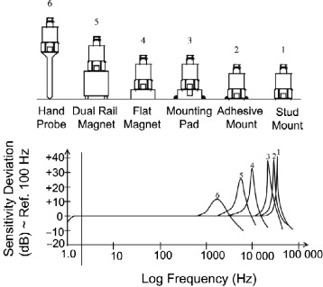
Stud mounting is the best technique to use to achieve the maximum frequency range. All sensor specifications and calibration information supplied with the sensor are based upon stud mounting during qualification tests. For best results, a smooth, flat surface should be prepared on the machinery surface as well as a perpendicular tapped hole of proper dimension. Spot face tools are available to simplify surface preparation. A thin layer of silicone grease or other lubricant should be applied to the surface and the sensor should be installed with the recommended mounting torque. Be sure to follow all installation recommendations including torque specifications supplied with each specific sensor model.
If drilling and tapping mounting holes into machinery structures is not practical, adhesive mounting is the next best technique. Sensors may be secured directly to the machine with adhesive or to a mounting pad with suitable tapped hole.
Mounting pads can be adhesively bonded or welded to machinery surfaces at specific vibration sensor installation points. The pads ensure that periodic measurements are always taken from the exact same location, lending to more accurate and repeatable measurement data. Pads with tapped holes are for use with stud mounted sensors, whereas the untapped pads are intended for use with magnetically mounted sensors.
For permanent installations, the pads facilitate mounting of sensors without actually machining the surface onto which they are to be installed. Also, the untapped pads may be utilized to achieve magnetic attraction on nonferrous surfaces.
Magnetic mounting offers the most convenient method of temporary sensor installation for route-based measurements and data collection. Magnetic mounting bases consist of rare-earth magnet elements to achieve high attraction forces to the test structure. This aids in high-frequency transmissibility and assures attraction for large heavy sensors and conditions of high vibration.
Rail mount styles are utilized for curved surfaces, such as motor housings and pipes. Knurled housings aid in gripping for removal. Hex-shaped magnetic bases are designed for smaller high-frequency sensors. All magnetic mounting bases should be manufactured from resilient, stainless steel.
Note: Exercise caution when installing magnetically mounted sensors by engaging the edge of the magnet with the structure and carefully rolling the sensor/magnet assembly to an upright position. Never allow the magnet to impact against the structure as this may damage the sensor by creating shock acceleration levels beyond survivable limits.
5.6.5. Applicable Standards
- ANSI S2.41, 1985 (R 1990), “Mechanical Vibrations of Machines with Operating Speeds from 10 to 200 Rev/s – Measurement and Evaluation of Vibration Severity in Situ,” American National Standards Institute, New York.
- ANSI Standards can be obtained from the Acoustical Society of America, Standards and Publications Fulfillment Center, P.O. Box 1020, Sewickley, PA 15143-9998.
- API 670, 1986, Vibration, Axial Position, and Bearing Temperature Monitoring System, 2nd ed., American Petroleum Institute, Washington, DC.
- API 678, 1981, Accelerometer-Based Vibration Monitoring System, API, Washington, D.C.
- European Standard—EN 13980: “Potentially Explosive Atmospheres, Application of Quality Systems.”
- ISO 7919, 1986, “Mechanical Vibrations of Non-Recipricating Machines—Measurements on Rotating Shafts and Evaluation,” International Standards Organization, Geneva, Switzerland.
- ISO 2372, 1974, “Mechanical Vibrations of Machines with Operating Speeds from 10 to 200 rpm—Basis for Specifying Evaluation Standards,” International Standards Organization, Geneva Switzerland.
- ISO Standards can be obtained from the Director of Publications, American National Standards Institute, New York, NY 10005-3993.
- Open Standards for Operations and Maintenance. Mimosa—4259 Niagara Ave., San Diego, CA 92107.
5.6.6. Latest and Future Developments
TEDS (transducer electronic data sheet) allows the operator to retrieve stored data from within the sensor. Data includes sensor numbers (for warranty and traceability), calibration info, date of manufacture, name of manufacturer and installation date, and location on the machine in which plant.
Wireless Sensors There has been a strong interest in implementing wireless technology in industrial applications. Until price, the smaller overall capacity of a wireless system versus a cable system, and powering of the sensor can be addressed, wireless technologies will only be used on very specialized niche applications.
5.6.7. Sensor Manufacturers
- Endevco
- GE Bently Nevada
- IMI Sensors, a Division of PCB Piezotronics, Inc.
- Kaman Instrumentation
- Kistler Instruments
- Metrix
- Monitran
- PCB Piezotronics, Inc.
- Vibrometer
- Wilcoxon Research
References and Resources
1 C.M. Harris, Shock and Vibration Handbook 4th edition 1996 McGraw-Hill New York
2 K.G. McConnell, Vibration Testing Theory and Practice 1995 John Wiley & Sons New York
3 Institute of Environmental Sciences and Technology. RP-DTE011.1, Shock and Vibration Transducer Selection.
1 Nelson L. Baxter, Machinery Vibration Analysis III 1995 Vibration Institute Willowbrook, IL
2 A.R. Crawford, S. Crawford, The Simplified Handbook of Vibration Analysis vol. 1 1992 Computational Systems, Inc.
3 R.C. Eisenmann Sr., R.C. Eisenmann Jr., Machinery Malfunction Diagnosis and Correction 1998 Prentice-Hall PRT Englewood Cliffs, NJ
4 Ronald L. Eshleman, Basic Machinery Vibrations: An Introduction to Machine Testing, Analysis, and Monitoring 1999 VIPress, Incorporated
5 Harris, Cyril M. Shock and Vibration Handbook. New York: McGraw-Hill.
6 P.H. Maedel Jr., Vibration Standards and Test Codes C.M. Harris, Shock and Vibration Handbook 4th edition 1996 McGraw-Hill New York
7 James I. Taylor, The Vibration Handbook 1994 Vibration Consultants, Inc. Tampa, FL
8 Victor Wowk, Machinery Vibration, Measurements and Analysis 1990 McGraw-Hill New York
- CMVA/ACVM (Canadian Machinery Vibration Association)
- Suite 877, 105-150 Crowfoot Crescent NW
- Calgary, AB T3G 3T2
- Ph: (403) 208-9618 Fax: (403) 208-9619 Web: www.cmva.com
- MFPT (Machinery Failure Prevention Technology)
- 1877 Rosser Lane
- Winchester, VA 22601
- Ph: (540) 678-8678 Fax: (540) 678-8799 Web: www.mfpt.org
- Vibration Institute
- 6262 S. Kingery Highway
- Suite 212
- Willowbrook, IL 60527
- Ph: (630) 654-2254 Fax: (630) 654-2271 Web: www.vibeinst.org
| Trade magazines/Web sites: | |
| Intech | www.isa.org |
| Maintenance Technology | www.mt-online.com |
| Reliability Magazine | www.reliability-magazine.com |
| Sensors | www.sensorsmag.com |
| Sound & Vibration | www.sandv.com |
| Turbomachinery International | www.turbomachinerymag.com |
| Vibrations | www.vibeinst.org |
| Companies/Web sites: | |
| GE Bently website | www.bently.com |
| Kaman Instrumentation Web site | www.kamaninstrumentation.com |
| PCB Piezotronics, Inc. Web site | www.pcb.com |
| IMI Sensors website | www.imi-sensors.com |