
Appendix Standard Interfaces
Most embedded systems interface to sensors and output devices directly. However, there are a couple of standard interfaces used in industrial applications. Devices meeting these specifications are usually attached to an industrial computer (industrial PC) or a programmable logic controller (PLC). They are briefly covered here, because the embedded designer may run into them somewhere along the way.
1. IEEE 1451.2
The IEEE 1451.2 is an open standard that provides a standard interface for sensors and actuators. IEEE 1451.2 defines the electrical and interface protocol. IEEE 1451 sensors and actuators contain an embedded microprocessor on a module called a smart transducer interface module (STIM). The STIM microprocessor handles the physical interface to the sensors and the standard interface to the controlling system. Each STIM can contain up to 255 sensors or actuators.
1.1. Electrical
IEEE 1451 is a 10-wire, synchronous, serial interface. Signals include +5V, ground, data-in and data-out lines, a clock, an interrupt, and other signals. IEEE 1451 STIMs are hot swappable, meaning they can be inserted and removed with power applied. Each IEEE 1451 STIM can support multiple transducers or actuators.
1.2. Transducer Electronic Data Sheets
IEEE 1451 specifies that each STIM have a transducer electronic data sheet (TEDS) This tells the controlling system certain parameters about the transducers on the module, including upper and lower range limits, warm-up time, calibration information, and timing information. The specification also includes additional TEDS parameters that are optional, some that are sensor specific, and some that are reserved for future extensions to the standard.
1.3. Standard Units
Information passed from an IEEE 1451 STIM must be in standard units. The actual sensor may be measuring temperature, voltage, current pressure, velocity, or any other real-world parameter. Whatever is being measured is converted to a standard unit before it is transmitted to the controlling processor via the IEEE 1451 interface. The IEEE 1451 standard permits sensors to support the following units:
- Length (in meters)
- Mass (in kilograms)
- Time (in seconds)
- Current (in amps)
- Temperature (degrees kelvin)
- Amount of substance (mole)
- Luminous intensity (candela)
- Plane angle (radians)
- Solid angle (meters2)
Whatever unit the sensor measures in must be converted to these standard units. A sensor may be measuring speed in miles per hour or furlongs per fortnight, but it must be converted by the STIM microprocessor to meters per second before transmission over the IEEE 1451 interface.
When the controlling processor reads sensor data from an IEEE 1451 sensor, what gets transmitted is a string of exponents, one for each of these values. The velocity-measuring example just given would output a positive exponent for meters and a negative exponent for seconds, making a meters/second result. All the other exponents would be 0 (anything to the 0 power, except 0, is 1). The standard also provides for digital data from a sensor or to an actuator.
Although this method complicates the software in the STIM microprocessor, it provides a standard interface for the controlling processor. In theory, any IEEE 1451 STIM can be attached to any IEEE 1451 controller and it will work.
2. 4–20-mA Current Loop
The 4–20-mA standard (Figure 1) uses the same pair of wires to power a remote sensor and to read the result. The controlling microprocessor, usually an industrial PC or other industrial computer, provides a voltage on a pair of wires. The controller also senses the current in the wires. The sensor converts whatever it is measuring (temperature, velocity, etc.) to a current value. The sensor draws 4 mA at one end of its measurement range, and 20 mA at full scale.
Figure 1. 4–20 mA current loop.
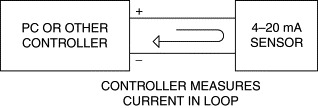
Because the 4–20-mA loop is differential, the system is suitable for sensors that are removed from the controller by quite a distance. Any common-mode noise is ignored by the current measurement circuit. One drawback to this method is the need for a pair of wires and sensing circuitry for every sensor in the system.
3. Fieldbus
Fieldbus is a digital, serial, two-way communications system that interconnects measurement and control equipment such as sensors, actuators, and controllers. Conceptually, Fieldbus provides a means to replace point-to-point connectivity of 4–20-mA sensors with a mutidrop connection that can communicate with multiple sensors over a single communication path (Figure 2). The Fieldbus specification describes a layered model, including the physical connection layer, a data link layer, and application layers.
Figure 2. Fieldbus.
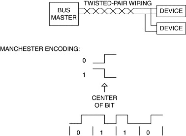
Fieldbus uses twisted-pair wiring. A single pair of wires provides both power and data communication. Fieldbus devices draw power from the wiring, just as 4–20-mA devices do. Data transmission is performed by changing the current drawn by the transmitting device; the current swing between 0 and 1 is 20 mA. The data rate is 31,250 bits per second using Manchester encoding. Manchester encoding always has a transition in the middle of the bit; one of the advantages of Manchester encoding is that the average DC value of the signal pair is zero because the bits are always high for 50% of the bit period and low for 50% of the period. The relatively low data rate permits very long cabling runs, which is important in large factory and plant control environments. Figure 2 shows Manchester encoding for one and zero bits, and for a bit string of 0110.
Fieldbus communication uses a combination of polling and token passing. Bus masters poll devices on the bus for information, and a Fieldbus device can transmit only when polled. If the bus has multiple masters, control of the bus is managed by a “token” that is “owned” by one master at a time. When a master is finished using the bus, it sends a message to the next master, handing off control of the bus to that master.
Available Fieldbus peripherals match those available in 4–20 mA format, and include such devices as pressure sensors, temperature sensors, flow measurement sensors, and controllable valves.