
Chapter 8. Pressure
8.1. Introduction
Pressure is one of the most important and widely measured quantities in industry. Accurate and traceable pressure measurement is important in many sectors, such as health, meteorology, transport, power. A variety of instruments are used for measurement of pressure and the basic operating principles of some of these instruments together with guidelines for their calibration are given in this chapter.
8.2. SI and Other Units
The SI unit for measurement of pressure is the newton (N) per square meter (m2), having the special name pascal (Pa). The pascal is comparatively small in magnitude and therefore for most practical measurements decimal multiples kilopascal, megapascal, and gigapascal are used. The other metric units commonly used for measurement of pressure are the bar, the kilogram-force per square centimeter, and millimeter of mercury. However, the use of the last unit is strongly discouraged due to its inadequate definition.
A popular nonmetric unit for measurement of pressure is the pound-force per square inch (lbf/in2). In both metric and nonmetric systems, sometimes pressures are erroneously indicated in mass units, such as “200 psi,” which should correctly be written as “200 pound-force per square inch” or “200 lbf/in2.” The definitions, symbols, and conversion factors of pressure units are given in Table 8.1.
Table 8.1. Definitions, symbols, and conversion factors of pressure units
| Unit | Symbol | Definition | Conversion factor |
|---|---|---|---|
| Pascal | Pa | 1 Pa = 1 N/1 m2 | |
| Kilogram-force per square centimeter | kgf/cm2 | 1 kgf/cm2 = 1 kgf/1 cm2 | 1 kgf/cm2 = 98 066.5 Pa (exactly) |
| Bar | bar | 1 bar = 105 Pa | 1 bar = 105 Pa |
| Pound-force per square inch | lbf/in2 | 1 lbf/in2 = 1 lbf/1 in2 | 1 lbf/in2 = 6894.76 Pa |
| Millimeter of mercury | mmHg | See Note 1 | 1 mmHg = 133.322 Pa |
| Inch of water | in H2O | See Note 2 | 1 in H2O = 248.6 Pa |
1 The conventional millimeter of mercury is defined in terms of the pressure generated by a mercury column of unit length and of assigned density 13,595 kg/m3 at 0° C under standard gravity of 9.80665 m/s2.
2 The conventional inch of water is defined in terms of the pressure generated by a water column of unit length and of assigned density 1000 kg/m3 subjected to standard gravity of 9.80665 m/s2.
The manometric units millimeter of mercury and inch of water depend on an assumed liquid density and acceleration due to gravity. Both of these assumptions inherently limit their relationship to the pascal. The use of these units, though given in Table 8.1 for sake of completeness, is strongly discouraged internationally. The pascal and its multiples and submultiples as appropriate to the magnitude of the pressure value are strongly recommended.
8.3. Absolute, Gauge, and Differential Pressure Modes
If a vessel were to contain no molecules within it, the pressure would be zero (Figure 8.1). Pressures measured on the scale with zero pressure as the reference point are said to be absolute pressures.
Figure 8.1. Pressure modes and their relationships.

The earth's atmosphere exerts a pressure on all objects on it. This pressure is known as the atmospheric pressure and is approximately equal to 100 kPa. Pressures measured in reference to the atmospheric pressure are known as gauge pressures. The difference between a pressure higher than atmospheric and atmospheric pressure is a positive gauge pressure, while the difference between atmospheric pressure and a pressure lower than atmospheric is referred to as negative gauge pressure or vacuum. Gauge pressure values being dependent on atmospheric pressure change slightly as the ambient pressure changes. The relationship between absolute and gauge pressure follows: (8.1)
![]()
A differential pressure is the difference of pressure values at two distinct points in a system. For example, the flow of a fluid across a restriction in a pipe causes a pressure differential and this is used to determine the flow of the gas or liquid. This is the principle of the orifice plate as shown in Figure 8.2.
Figure 8.2. Differential pressure in an orifice plate.

8.4. Primary Standards
A number of different physical standards are used for the realization of pressure values at the primary level. The two most common instruments for the positive gauge pressure range are the mercury manometer and deadweight pressure tester. The spinning ball gauge standard is used in the negative gauge pressure (vacuum) range.
8.4.1. Mercury Manometer
The basic principle of the mercury manometer is illustrated in Figure 8.3. Vessels A and B are connected using a flexible tube. Vessel A is at a fixed level while vessel B can be moved up and down using a lead screw mechanism. The output pressure is obtained from vessel A.
Figure 8.3. Mercury manometer.

A vacuum pump is sometimes used to evacuate the air above the meniscus of the moving vessel. Under these conditions the output pressure Pout is given by (8.2)
![]() where
where
- Pin = the pressure due to the gas above the meniscus of the moving vessel
- h = the difference of height between the mercury levels of the two vessels
- ρ = the density of mercury
- g = local acceleration due to gravity
In some designs, large diameter tubes (several tens of millimeters) are used to reduce capillary depression of the meniscus and other surface tension effects.
With these measures uncertainties in pressure of a few parts per million can be achieved. However the mercury temperature (typically to 0.005° C), the mercury density, the vertical distance between the mercury levels, and the local value of gravitational acceleration have to be determined with low uncertainties. Individually built large-bore mercury manometers, using a variety of optical, capacitive, ultrasonic, or inductive methods for detecting the mercury surface positions, are used in many national laboratories as primary standards. Slightly less capable instruments are available commercially and measure pressures up to about 3 × 10⁵ Pa.
8.4.2. Deadweight Pressure Tester
A deadweight pressure tester consists of three main elements, namely, the pressure balance, set of deadweights, and the pressure source. A schematic of a deadweight pressure tester in its simplest form is shown in Figure 8.4.
Figure 8.4. Deadweight pressure tester.
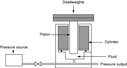
The pressure balance consists of a piston inserted into a closely fitting cylinder. The set of weights is usually made from nonmagnetic stainless steel in the form of discs stackable on top of each other. Hydraulic pressure generated by a manual or electrically driven pump or pneumatic pressure obtained from a pressurized vessel is applied to the piston/cylinder assembly of the pressure balance.
Pressure testers used as primary-level standards are calibrated by absolute methods by estimating the effective diameter and deformation characteristics of the piston/cylinder assembly together with the determination of the mass values of the weights (see Section 8.7.1.5). Deadweight pressure testers are used in the range 3 kPa (gas media, absolute, or gauge mode) up to 1 GPa (hydraulic, gauge mode). Uncertainties on the order of ±0.001% of the reading are attainable with these instruments.
8.5. Spinning Ball Gauge Standard
A spinning ball gauge standard uses the principle of molecular drag to estimate the molecular density of a gas from which the pressure can be calculated. These standards can only be used for measurement of low absolute pressures below 10 kPa. The principle of the spinning ball gauge standard is illustrated in Figure 8.5.
Figure 8.5. Spinning ball gauge standard.

A ball made of magnetic steel a few millimeters in diameter is housed in a nonmagnetic tube connected horizontally to a vacuum chamber. The ball is magnetically levitated and spun to few hundred revolutions per second using a rotating magnetic field. The driving field is then turned off and the relative deceleration of the ball is measured with magnetic sensors. The deceleration of the ball due to molecular drag is related through kinetic theory to molecular density and pressure of the gas. The lowest pressure that can be measured is limited by the residual drag caused by induced eddy currents.
An inert gas, usually dry nitrogen, is used as the pressure medium. The temperature of the tube is measured accurately using a calibrated thermocouple or other instrument. The spinning rotor gauge is used in the absolute pressure range 10−5 Pa to 10 Pa.
8.6. Secondary Standards
The mercury manometer, deadweight tester, and capacitance standard are the most commonly available secondary standards. A brief description of the capacitance pressure standard is given here as the other two standards, namely, the mercury manometer and the deadweight tester, are covered in other sections.
8.6.1. Capacitance Pressure Standard
A schematic diagram of a capacitance pressure standard is shown in Figure 8.6. Capacitance standards basically consist of a parallel plate capacitor whose plates are separated by a metallized diaphragm. The diaphragm and the two electrodes form two capacitors that are incorporated in an AC bridge circuit. The deflection of the diaphragm when a pressure is applied to one of the chambers is detected as a change in the capacitances. The two pressure chambers are electrically isolated and the dielectric properties are maintained constant.
Figure 8.6. Capacitance pressure standard.

The symmetrical design provides a more or less linear relationship between pressure and electrical output and differential pressures can be easily measured. To measure absolute pressures the reference chamber is evacuated.
Capacitance pressure standards operate in the pressure range 10−3 Pa to 107 Pa and generally have good repeatability, linearity, and resolution. They also have high overpressure capability.
8.7. Working Standards
The most commonly used working standard is the deadweight pressure tester.
A number of other instruments, such as precision bourdon or diaphragm-type dial gauges, strain gauges, piezoresistive pressure sensors, and liquid manometers are also used as working standards.
8.7.1. Deadweight Pressure Tester
8.7.1.1. The Pressure Balance
The most critical element of a deadweight pressure tester is the pressure balance. Pressure balances normally encountered are of two kinds, hydraulic (uses oil as the pressure medium) and pneumatic (uses air or nitrogen as the pressure medium). The latter type often has a facility to evacuate the ambient space around the piston/cylinder assembly, thus permitting their use for absolute as well as gauge pressure measurements.
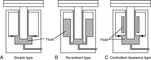
The simple, re-entrant, and the controlled clearance types shown in Figure 8.7 are the three basic types of pressure balances in common use today. Although there are a number of technical and operational differences, the general principle of pressure measurement for the three types is the same.
Figure 8.7. Types of pressure balance.
8.7.1.2. Simple Type
The geometry illustrated schematically in Figure 8.7(A) is that of the simple type, where the piston and cylinder have basic cylindrical shapes. The calculation of the elastic deformation of this design is straightforward. Because fewer variables are needed to predict the deformation, the pressure coefficients can be estimated with a relatively small uncertainty. This design is commonly used for pressures up to 500 MPa and sometimes with appropriate modifications up to 800 MPa. At higher pressures distortion of the piston and cylinder becomes significant and the annular gap between the piston and cylinder is so large that the gauge does not operate well.
8.7.1.3. Re-entrant Type
In the re-entrant type, illustrated schematically in Figure 8.7(B), the pressure transmitting fluid acts not only on the base of the piston and along the engagement length of the piston and cylinder but also on the external surface of the cylinder. This external pressure reduces the gap between the piston and the cylinder thus reducing fluid leakage. The upper pressure limit is set by the reduction of the gap to an interference fit.
The disadvantage of this design is that it is difficult to accurately estimate the effects of distortion on the effective area of the piston and cylinder.
8.7.1.4. Controlled Clearance Type
In the controlled clearance type, illustrated schematically in Figure 8.7(C), an external pressure is applied to the exterior surface of the cylinders enabling control of the gap between the piston and the cylinder. Using this design, in principle a very wide range of pressures can be covered using only one piston/cylinder assembly. However, in practice a series of assemblies is used to achieve the best sensitivity for a particular pressure range. This type of pressure balance is most commonly used in very high-pressure applications.
8.7.1.5. Simple Theory of the Pressure Balance
The simple theory of the pressure balance is based on the application of laws of hydrodynamics or aerodynamics depending on whether the pressure transmitting medium is a liquid or a gas. The simple theory is explained using Figure 8.8.
Figure 8.8. Diagrammatic representation of the pressure balance piston/cylinder assembly (with clearances greatly exaggerated).

The piston and cylinder are assumed to have straight and smooth cylindrical surfaces of circular cross section of radii r and R, respectively. The fluid pressure being measured, P1, is applied to the base of the piston, while the top of the piston is exposed to ambient pressure, P2. At the equilibrium condition the upward vertical force arising from the pressure difference P1 – P2 is balanced against a known downward gravitational force, W, which is applied to the piston by means of calibrated masses.
When the piston is in equilibrium, (8.3)
![]() where F represents a frictional force exerted on the vertical flanks of the piston by the fluid that is being forced to flow upward
under the influence of the pressure gradient.
where F represents a frictional force exerted on the vertical flanks of the piston by the fluid that is being forced to flow upward
under the influence of the pressure gradient.
The vertical component of the fluid velocity is at a maximum approximately halfway between the bounding surfaces (piston and cylinder surfaces) and it is zero at the bounding surfaces. The cylindrical surface at which the fluid velocity is maximum and frictional forces between adjacent layers are minimum is called the neutral surface.By equating the forces acting on the column of fluid of annular cross section contained between the surface of the piston and the neutral surface, and denoting the downward force due to its weight as w the following equation is obtained: (8.4)
![]()
Combining Equations (8.3) and (8.4) gives (8.5)
 where
where
![]() is defined as the effective area, AP, of the piston/cylinder assembly, that is, the quantity by which the applied force must be divided to derive the applied
pressure. It is a function of the dimensions of both the piston and the cylinder. The effective load strictly includes the
force due to the mass of the annular column of fluid between the neutral surface and that of the true piston, but this is
normally negligible. Hence, the applied gauge pressure P = (P1 – P2), that is, the amount by which the pressure within the system exceeds the external pressure at the reference level (the base
of the piston or an identified plane), is to a good approximation given by (8.6)
is defined as the effective area, AP, of the piston/cylinder assembly, that is, the quantity by which the applied force must be divided to derive the applied
pressure. It is a function of the dimensions of both the piston and the cylinder. The effective load strictly includes the
force due to the mass of the annular column of fluid between the neutral surface and that of the true piston, but this is
normally negligible. Hence, the applied gauge pressure P = (P1 – P2), that is, the amount by which the pressure within the system exceeds the external pressure at the reference level (the base
of the piston or an identified plane), is to a good approximation given by (8.6)

In practice a number of deviations from the ideal form are found in both pistons and cylinders. Therefore, in order to calculate the effective area from dimensional data, measurements are required that yield information on the roundness and straightness of the components as well as their absolute diameters.
From the theory of elastic distortion it can be shown that the variation of the effective area, AP, of a simple piston/cylinder with applied pressure P is essentially linear: (8.7)
![]() where A0 is the effective area for zero applied pressure, the deviations from linearity in practice being small. Also the dimensions
of the components should be relatively large to reduce the uncertainties associated with diametral measurements to an acceptable
level. Furthermore this method yields the value of the effective area at zero applied pressure and does not take into account
the variation of the effective area of the assembly due to the elastic distortion of both piston and cylinder with applied
pressure.
where A0 is the effective area for zero applied pressure, the deviations from linearity in practice being small. Also the dimensions
of the components should be relatively large to reduce the uncertainties associated with diametral measurements to an acceptable
level. Furthermore this method yields the value of the effective area at zero applied pressure and does not take into account
the variation of the effective area of the assembly due to the elastic distortion of both piston and cylinder with applied
pressure.
An estimate of the distortion coefficient, a, for the simple type of piston/cylinder assembly can be calculated directly from dimensions and the elastic constants of the materials. However, due to the complexity of the forces acting on both components in any but the simplest designs, this method is somewhat limited.
For general purposes, these quantities are evaluated by comparing the pressure balance with a primary standard instrument, in a procedure often referred to as cross floating, (see Section 8.9 on calibration of pressure measurement standards).
8.7.1.6. Corrections
In practice a number of corrections are required to determine gauge pressure using a deadweight pressure tester.
Temperature Correction
The calibration certificate of a pressure tester will normally give the effective area value at a reference temperature of 20° C. If the temperature of the piston/cylinder assembly in use is different from the reference temperature, a correction is required. This is usually combined with the pressure distortion coefficient a and expressed as (8.8)
![]() where
where
- AP,t = the effective area of the piston/cylinder assembly at applied pressure P and temperature t
- A0,20 = the effective area of the piston/cylinder assembly at zero applied pressure and 20° C
- a = pressure distortion coefficient of the piston/cylinder assembly
- αp = linear expansion coefficient of the piston
- αc = linear expansion coefficient of the cylinder
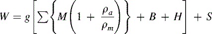
Evaluation of Force
The general equation for the evaluation of downward force for an oil-operated deadweight pressure tester is given by (8.9)
 where
where
- W = net downward force exerted by the weights and the piston assembly
- g = local acceleration due to gravity
- M = conventional mass of the component parts of the load, including the piston
- ρa = density of ambient air
- ρm = density of the mass M, and can be significantly different for each load component
- B = correction due to fluid buoyancy acting on the submerged parts of the piston
- H = fluid head correction
- S = correction for surface tension
Air Buoyancy Correction
The factor 1 – ρa/ρm corrects for air buoyancy effects. It has a value approximately 0.99985 when working in air at one atmosphere and with steel weights. If there are significant differences of the densities of the weights, weight carrier, and the piston, the corrections are separately worked out and added together.
The density of ambient air depends on the atmospheric pressure, temperature, relative humidity, and composition. For very accurate work these parameters are measured and the air density calculated from an empirical equation. The approximate density of ambient air is 1.2 kg/m3.
Fluid Buoyancy Correction
The fluid buoyancy force correction is calculated as an upthrust equivalent to weight of the volume of fluid displaced by the submerged part of the piston. The volume of fluid concerned depends on the reference level chosen for specifying the applied pressure.
Fluid Head Correction
The output pressure of a deadweight pressure tester is usually obtained at a level different from the reference level of the tester. A correction is then required to take account of the difference in levels. It is more convenient to combine the fluid head correction with the fluid buoyancy correction, and the combined correction factor expressed as a load correction is given by (8.10)
![]() where
where
- h = difference in levels between the pressure output and reference plane of the pressure tester
- A = nominal effective area of the piston
- v = volume of fluid displaced by the piston
- ρf = density of the fluid
Surface Tension Effects
A correction to account for the surface tensional forces acting on the piston is included. This correction is given by (8.11)
![]() where
where
- S = force due to surface tension
- s = surface tension of the fluid
- C = circumference of the floating element at the point of emergence from the fluid
Summary
Taking all these correction terms into account, the applied pressure at the specified reference level is obtained from the equation (8.12)

8.7.2. Portable Pressure Standard (Pressure Calibrator)
A variety of portable pressure standards, also known as pressure calibrators, that use strain gauge, capacitance, and piezoresistive transducers, are available from a number of manufacturers. Usually these consist of a portable pressure pump, pressure transducer assembly, and associated electronics and display. These are very convenient for calibration of pressure gauges and transmitters used on-line in a large number of process industries. However, these instruments require frequent calibration against a secondary pressure standard maintained in a laboratory. Instruments ranging up to 800 kPa with an accuracy of ±0.5% of the reading are available. Portable type deadweight pressure balances of the hydraulic type up to 70 MPa and pneumatic type up to 200 kPa are also in use.
8.8. Pressure Measuring Instruments
8.8.1. Liquid Column Instruments
8.8.1.1. Mercury Barometers
Mercury barometers are generally used for measuring ambient pressure. There are two popular types, Fortin barometer and Kew pattern barometer.
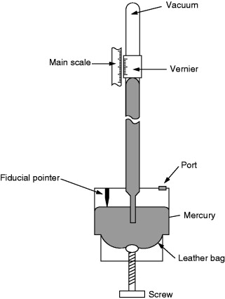
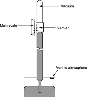
Fortin Barometer
A Fortin barometer (Figure 8.9) can be used only to measure ambient pressure over the normal atmospheric pressure range. The height of the mercury column is measured using a vernier scale. A fiducial point mounted in the cistern determines the zero of the vertical scale. The mercury level in the cistern can be adjusted up or down by turning a screw to squeeze a leather bag. In making a measurement the instrument is made vertical with the help of a spirit level mounted on it and the screw is turned until the mercury meniscus in the cistern just touches the fiducial point. The vernier scale is then adjusted to coincide with the upper mercury meniscus and the reading is read off the scale.
Figure 8.9. Fortin barometer.
In addition to the corrections recorded in the calibration certificate, corrections are needed to take account of instrument temperature and value of gravitational acceleration. Details of these corrections are given in British Standard BS 2520.
Mercury barometers handled properly are very reliable instruments. They should be transported with extreme care.
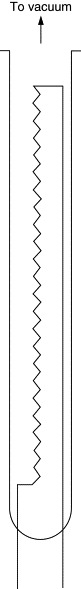
Kew Pattern Barometer
A version of the Kew pattern barometer (Figure 8.10), known as the station barometer, is similar to a Fortin barometer except that it has a fixed cistern. In this version the scale is contracted slightly in order to compensate for the varying mercury level in the cistern.
Figure 8.10. Kew pattern barometer.
Kew pattern bench barometers are free standing and pressures from a few millibars to atmospheric can be measured. These use a pressure port and do not need total immersion calibration.
As in the case of the Fortin barometer, corrections are needed for changes in temperature and local gravitational acceleration. These are again given in the British Standard BS 2520.
Precautions for Handling of Mercury Barometers
Great care is needed in the transportation of mercury barometers primarily to avoid changing their metrological properties and exposing people and the environment to toxic mercury vapor. For transportation they should be sealed in rupture- and leakproof plastic bags.
The glass tube of a Fortin barometer can be broken if mercury is allowed to oscillate up and down, while it is being moved in the upright position. To prevent this occurring or air entering the tube during transportation, the axial screw is turned until mercury has risen to within about 25 mm of the top of the tube. The barometer is then inclined slowly until mercury just touches the top of the tube, then continuing until the instrument is somewhere between horizontal and completely upside down.
Kew station barometers that do not have an axial screw should be treated similarly to Fortin barometers and turned slowly until horizontal or upside down.
In the case of Kew bench-type barometers, mercury in the tube should be isolated from the atmosphere before transportation, either with the tube nearly empty or nearly full. Some designs provide transportation sealing screws to achieve this but sealing the pressure port is sufficient. Additional packaging is applied between the tube and the barometer's frame, when transporting with the barometer's tube nearly full. The barometer is transported in the normal upright position.
Risk of spillage can also be reduced by ensuring that mercury barometers are placed in locations where they cannot be easily accidentally damaged.
8.8.1.2. U-Tube Manometer
A U-tube manometer is one of the most simple instruments used for measurement of pressure. It consists of a tube made from glass or other material (PVC or polythene) bent to the shape of a U and filled with a liquid, Figure 8.11.
Figure 8.11. U-tube manometer.

The fundamental principle that the absolute pressure on the same horizontal plane in a given liquid is constant is used in the U-tube manometer. In mathematical form this principle is expressed in the following equation: (8.13)
![]() where
where
- P1 and P2 = pressure at points 1 and 2
- h = the difference of height between the fluid levels of the two limbs
- ρ = the density of manometric liquid
- g = local acceleration due to gravity
If P1 = P2, that is when both ends of the U-tube are subjected to the same pressure, the levels of the liquid column will be at the same horizontal level. If, however, one limb is at a higher pressure than the other, the liquid column in that limb is depressed. The pressure difference between the two limbs is read off as the difference in heights of the liquid columns in the two limbs.
Mercury, water, and oil are all used in various designs of manometer. For measuring large pressure differences, mercury is frequently used as its density is over 13 times greater than that of water or oil and thus, for a given pressure, it requires a much shorter column. Density of mercury is also considerably more stable than that of other liquids.
Water or oil liquid columns are used to measure low-gauge and differential pressures. In some designs the manometer is inclined as this increases its sensitivity, the fluid having further to travel along the inclined column to achieve a given vertical movement. The traditional units for this type of measurement were inches of water or millimeters of water, but as units they are poorly defined and as mentioned earlier their continued use is strongly discouraged.
8.8.2. Mechanical Deformation Instruments
8.8.2.1. Bourdon Tube Gauge
A metallic tube of elliptical cross section that is bent to form a circular arc is the sensing element of a Bourdon tube dial gauge. The application of a pressure to the open end of the tube straightens it out. The movement of the free end of the tube is amplified mechanically using gears and levers to operate a pointer. Bourdon tube dial gauges operate at pressures up to about 1.5 GPa and a typical mechanism is shown in Figure 8.12.
Figure 8.12. Mechanism of a Bourdon tube pressure gauge.

Bourdon tube dial gauges are most commonly used for measuring gauge pressure but can also be used to measure absolute pressures by sealing the case. Differential pressure measurement is achieved by use of a second tube whose movement is mechanically subtracted from the main tube.
8.8.2.2. Diaphragm Gauge
The diaphragm dial gauge (Figure 8.13) is similar to a Bourdon tube dial gauge except that the moving element is a diaphragm. Its movement is transmitted through a connecting rod to an amplifying lever and gears that rotate a mechanical pointer.
Figure 8.13. Diaphragm dial gauge mechanism.

Differential pressure is easily measured by applying it across the diaphragm.
8.8.2.3. LVDT
A linear variable differential transformer (LVDT) pressure transducer (Figure 8.14) consists of a cylinder of ferromagnetic material moving inside a metallic tube. The end of the cylinder is attached to a deflecting component such as a diaphragm or bellows to which the test pressure is applied. Three coils are mounted on the tube. The central primary coil is excited with an alternating voltage. The two sensing coils, one on either side, are used for signal collection. As the magnetic cylinder moves within the tube, the magnetic field coupling, between the primary and secondary coils, changes. With suitable electronics, which may include temperature compensation, a linear relationship between cylinder position and output can be obtained. Sensors of this type are used in pressure transducers operating between pressures of about 10 mPa and 10 MPa.
Figure 8.14. LVDT pressure transducer.
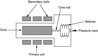
The cylinder end may need support as the attachment of the pressure-sensing element increases the weight and stiffness of the LVDT. LVDT pressure transducers are more commonly available as gauge or differential pressure devices. Absolute pressure units are more complex.
8.8.2.4. Piezoelectric Devices
When certain types of crystalline materials are subjected to an external pressure, an electric charge proportional to the rate of change of applied pressure is generated on the crystal surface. A charge amplifier is used to integrate the electric charges to give a signal that is proportional to the applied pressure. The response is very fast, making these sensors suitable for dynamic pressure and peak pressure measurement. However, these sensors cannot be used for measurement of steady pressure values.
Early piezoelectric transducers used naturally grown quartz but today mostly artificial quartz is used. These devices are often known as quartz pressure transducers. A piezoelectric crystal being an active sensor requires no power supply. Also the deformation of the crystal being very small makes them have good high-frequency response.
The major use of this type of sensor is in the measurement of very high-frequency pressure variations (dynamic pressure) such as in measuring pressures in combustion chambers of engines. They are also capable of withstanding high overpressures.
8.8.3. Indirect Instruments
8.8.3.1. Thermal Conductivity Gauges
Pirani Gauge
In a Pirani gauge (Figure 8.15), the energy transfer from a hot wire through a gas is used to measure the pressure of the gas. The heat energy is transferred to the gas by conduction and the rate of transfer depends on the thermal conductivity of the gas. The performance of these instruments therefore is strongly dependent on the composition of the gas.
Figure 8.15. Pirani gauge.
In the traditional configuration, a thin metal wire loop is sealed at one end of a glass tube whose other end is exposed to the gas. Tungsten, nickel, iridium, or platinum is used as the material of the wire. In another type, the gauge sensor is a micromachined structure, usually made from silicon covered by a thin metal film, such as platinum.
The wire or the metal film is electrically heated and its resistance, which is dependent on its temperature, is measured by incorporating the sensor element in a Wheatstone bridge circuit. There are three common operating methods: constant temperature method, constant voltage bridge, and the constant current bridge.
The main drawback of Pirani gauges is their strong gas composition dependence and their limited accuracy. The reproducibility of Pirani gauges is usually fairly good as long as no heavy contamination occurs. The measuring range of Pirani gauges is approximately from 10−2 Pa to 105 Pa, but the best performance is usually obtained between about 10−1 Pa and 103 Pa. A variant of the Pirani gauge, known as convection enhanced Pirani gauge, is able to measure pressures in the range 10−2 Pa to 105 Pa.
8.8.3.2. Ionization Gauges
A convenient method of measuring very low absolute pressures of a gas is to ionize the gas and measure the ionization current. Most practical vacuum gauges use electrons of moderate energies (50–150 eV) to perform the ionization. The resulting ion current is directly related to pressure and a calibration is performed to relate the gas pressure to ionization current. However, these can only be used over a finite range of pressures. The upper pressure limit is reached when the gas density is so large that when an ion is created it has a significant probability of interacting with either a neutral gas molecule or free electrons in the gas so that the ion is itself neutralized and cannot reach the collector. For practical purposes this can be taken as 10−1 Pa. The lower pressure limit of an ionization gauge is around 10−6 Pa. This limit is reached when either electric leakage currents in the gauge measuring electronics become comparable to the ion current being measured or when another physical influence factor (e.g., extraneous radiation) gives rise to currents of similar magnitude.
Two types of ionization gauges are in widespread use, the hot cathode ionization gauge and the cold cathode ionization gauge.
Triode Gauge
The triode gauge is a hot cathode type gauge. The gauge has been originally developed from the electronic valve. Electrons are emitted from a hot filament along the axis of the cylindrical grid, Figure 8.16. The ions are created mainly inside the grid and are attracted to the cylindrical anode around the grid. The usual pressure range of the instrument is about 10−1 Pa to 10−6 Pa. A special design, the Schultz-Phelps gauge, can operate in the approximate range 102 Pa to 10−2 Pa.
Figure 8.16. Triode gauge.

Bayard-Alpert Gauge
In the Bayard-Alpert design, the hot filament is outside of the cylindrical grid, Figure 8.17. Ions are created mainly inside the grid and are collected on an axial collector wire. Some of the electrons produced as a result of the ionization of the gas molecules will generate X-rays when they hit the grid. X-rays hitting the collector may eject electrons from the surface and they will be indistinguishable from ions arriving at the collector. Due to the much smaller solid angle subtended by the collector wire, fewer of the X-rays will strike the collector, resulting in a significantly lower pressure limit than for the triode gauge. This is the most common configuration for a hot filament ionization gauge. The pressure range is roughly 10−1 Pa to 10−9 Pa.
Figure 8.17. Bayard-Alpert gauge.

Penning Gauge
The Penning gauge is a cold cathode type gauge. A schematic of the gauge head is shown in Figure 8.18. In this gauge both electric and magnetic fields are used to generate and collect the ions. The anode may take the form of a ring or cylinder. When the electric field is high enough (a few kilovolts of direct current), a gas discharge is initiated by the use of a miniature ultraviolet light source. Emission of electrons then takes place from the cathode plates. The loop anode collects ions. The pressure range is approximately 10−1 Pa to 10−7 Pa.
Figure 8.18. Penning gauge.

8.9. Calibration of Pressure Standards and Instruments
8.9.1. General Considerations
The most important general concepts relating to calibration of pressure standards and measuring instruments are discussed in this section.
8.9.1.1. Reference Standard
The hierarchy of pressure measurement standards is given in Figure 8.19, which may be used for selection of the next higher-level standard for the calibration of a particular standard or instrument. However, the traceability path given in this diagram is not the only possible solution. What is indicated is one of many possible solutions.
Figure 8.19. Hierarchy of pressure measurement standards.
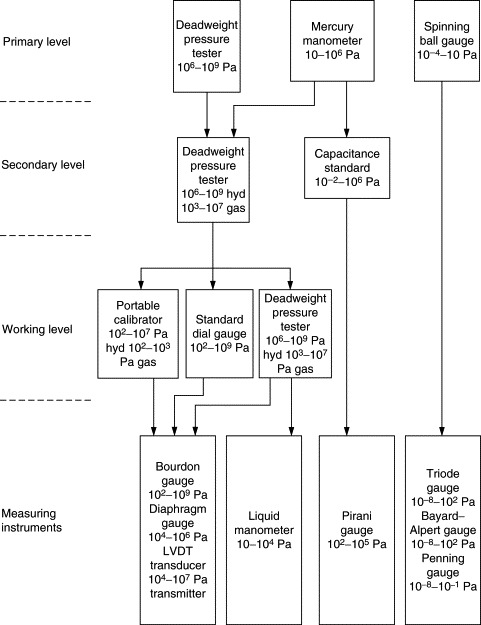
Primary standards are the deadweight pressure tester, mercury manometer, and spinning ball gauge. Secondary standards are those calibrated against the primary standard, namely, deadweight pressure testers and capacitance standards. Working standards are deadweight testers, precision dial gauges (Bourdon tube or diaphragm type), and portable field type standards. A variety of these standards of different types (deadweight pressure balances, piezoresistive devices, strain gauge type) are available. These are very useful for field calibrations.
8.9.1.2. Test Uncertainty Ratio
The uncertainty required for a particular standard or test instrument is an important criterion to consider before a calibration is performed. The uncertainty assigned to a primary, secondary, or working standard is usually quoted at 95% confidence level or coverage factor k = 2. However, this is only one component of the uncertainty budget. All other components of the system should be estimated. The usual criterion is that the combined uncertainty of the pressure calibration system including the higher-level standard used should be at least three to four times smaller than the required uncertainty of the device under calibration. In some circumstances, when the item to be calibrated has a very low uncertainty, a test uncertainty ratio of 1:1 may have to be used.
8.9.1.3. Reference Conditions
Primary, secondary, and working level pressure standards are always calibrated in a laboratory having stable ambient temperature and pressure. Most pressure measuring instruments are also calibrated in an environment with stable ambient temperature and pressure. In field conditions using portable equipment, such stable environments may not be found. In such cases it is difficult to evaluate the uncertainties of the calibration in a meaningful way as all effects of the poor environment may not be quantifiable. Also the reference standard itself may not have been calibrated under similar conditions. It is thus more common to calibrate measuring instruments also under stable conditions and apply separately determined corrections to take account of poor in-service environments.
8.9.1.4. Local Gravity
The generated pressure values given in a calibration certificate of a pressure balance are usually referenced to the standard value of the acceleration due to gravity, namely, 9.80665 m/s2. If the local value of gravity differs significantly from the standard gravity, the generated pressure values need to be corrected using the value of local gravity.
8.9.1.5. Range of Calibration
The range of calibration should be carefully considered. A pressure measuring instrument or standard is normally calibrated throughout its total range at least at five pressure levels. For determination of effective area of pressure balances, at least 10 pressure levels are required. To detect hysteresis effects, increasing as well as decreasing pressure is used. Calibration over 20% to 100% of rated range is usual.
8.9.1.6. Recalibration Interval
The interval between calibrations of a pressure standard or test instrument is dependent on the type of transducer, uncertainty specification, conditions, and frequency of use. For instruments with electrically operated sensors and electronic signal conditioning circuits, the manufacturer's specification for the device, particularly the specification for the long-term stability, is a good starting point for the determination of the recalibration interval. In most standards laboratories secondary standard deadweight testers (or pressure balances) are given a three-year recalibration interval. Diaphragm capacitance standards and associated electronics are susceptible to drift and may need a shorter interval (one to two years).
It is possible to determine the approximate recalibration interval after several calibrations, if as found calibration data are recorded in the calibration report. If the calibration values change significantly at each calibration, then the interval may be too long. On the other hand if there is no appreciable change in the calibration values, the interval may be too short.
8.9.1.7. Pipework and Tubing
Most positive-gauge pressure measuring instruments are calibrated by connecting their pressure ports to a pressure standard using suitable pipework or special tubing rated for high-pressure work. It is important to make sure that the pipework or tubing used is of good quality, undamaged, and has a rating higher than the maximum pressure to be applied. The piping and joints should be inspected for leaks before the application of the maximum pressure. It is very important to ensure that the system is safe for operation at the maximum pressure envisaged. Guidance is available from a number of sources, particularly the High Pressure Safety Code published by the High Pressure Technology Association.
8.9.1.8. Pressure Medium
It is necessary to use the same pressure medium for the calibration as when the instrument is used. For example, instruments for measuring gas pressure should not be calibrated using oil as the pressure medium. The reverse is also true. In circumstances where two different media have to be used, a separator cell is used to transfer the pressure from one medium to the other.
The pressure medium used, whether it be oil or a gas, should be clean and free of moisture. Filtered air or dry nitrogen is the preferred gas for calibration of gas pressure measuring instruments. Mineral or synthetic oils are used for hydraulic instruments. Certain oils may not be compatible with materials of some pressure system components. Also electrical conductivity of the oil is important when resistance gauges are being used. Instrument manufacturers usually recommend commercial oil types, which are suitable and their advice should be followed.
8.9.1.9. Instrument Adjustment
Calibration of an instrument necessarily involves adjustment of the instrument where this is possible. Adjustments are performed until the deviations are minimum throughout the useful range. A number of repeat adjustments and test runs are required before an optimum level of deviations can be obtained.
8.9.2. Calibration of Working Standard Deadweight Pressure Testers
Generally, working standard deadweight pressure testers are calibrated by comparing them with a secondary standard deadweight pressure tester in a procedure known as cross floating. Two methods are possible.
Method A—Generated Pressure Method
The deviation of the nominal pressure value (usually marked on the weights) from the generated pressure is determined at a number of loads. The repeatability of the pressure balance is also determined. The determination of the conventional mass values of the weights and other floating components is optional.
Method B—Effective Area Determination Method
- The conventional mass values of all the weights, weight carrier, and the piston of the pressure balance if removable
- The effective area AP of the piston/cylinder assembly of the pressure balance as a function of pressure, at the reference temperature (usually 20° C)
- The repeatability as a function of the measured pressure
In method A, the deviation of the nominal pressure from the generated pressure and its uncertainty at each pressure level is ascertained. Method B, which is more time consuming, produces a complete calibration certificate with values for the effective area, mass values of the weights, and their uncertainties.
The choice of the procedure to be followed in a particular case depends on a number of considerations, the most important being the uncertainty of the instruments to be calibrated using the deadweight tester.
8.9.2.1. Cross Floating
In a cross-floating system two pressure balances are interconnected into a common pressure system. When the loads on the two pressure balances are adjusted so that both are in equilibrium, the ratio of their total loads represents the ratio of the two effective areas at that pressure. The attainment of the equilibrium condition is the critical part of the measurement.
A single-medium hydraulic cross-float system between two deadweight pressure testers is shown in Figure 8.20. A variable-volume pump is used to pressurize the system and to adjust the float positions of the two pressure balances. An isolation valve is used to isolate the pump from the system to check for leaks. The two pressure balances are isolated from each other for determining sink rates of each balance independently. A sensitive differential pressure indicator and a bypass valve are inserted in line between the two pressure testers. The differential pressure indicator, though not essential, serves a useful purpose by indicating the pressure difference between the two testers and speeds up obtaining a balance.
Figure 8.20. Typical arrangement for cross floating two hydraulic deadweight pressure testers.
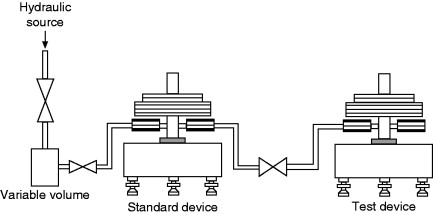
A similar arrangement is used in a two-media (hydraulic and gas) cross-float system except that an additional component, a media separator cell, is required to transmit the pressure from one medium to the other. A differential pressure indicator is also used, as in the case of the single-medium system.
8.9.2.2. Estimation of Uncertainty
The combined uncertainty of the measured pressure depends on a number of input uncertainties. The combined standard uncertainty and the expanded uncertainty are calculated using the standard uncertainties estimated for each input component.
The main input components for method A and method B follow.
Method A
Type A Uncertainties
Repeatability of the pressure balance is estimated at all loads by computing the standard deviation of the difference between the nominal and generated pressure. It is expressed in pascals, or as percentage of the nominal pressure.
Type B Uncertainties
- Uncertainty of the pressure reference standard
- Uncertainty of the mass values
- Uncertainty of the local gravity
- Uncertainty due to temperature
- Uncertainty due to the head correction
- Uncertainty due to tilt (negligible if perpendicularity was duly checked)
- Uncertainty due to air buoyancy, if significant
- Uncertainty due to spin rate and/or direction, eventually
- Uncertainty of the residual pressure (absolute mode only)
Method B
Type A Uncertainty
Repeatability of the pressure balance is estimated at all loads by computing the standard deviation of the difference between the reference and generated pressure. It is expressed in pascals, or as percentage of the reference pressure.
Type B Uncertainties
- Uncertainty of the mass values
- Uncertainty of the measured effective area, including the uncertainty estimated using a type A method
- Uncertainty due to the pressure distortion coefficient, when relevant, including the uncertainty estimated using a type A method
- Uncertainty of the local gravity
- Uncertainty due to the temperature of the balance
- Uncertainty due to the air buoyancy
- Uncertainty due to the head correction
- Uncertainty due to tilt (negligible if perpendicularity was duly checked)
- Uncertainty due to spin rate and/or direction, eventually
- Uncertainty of the residual pressure (absolute mode only)
8.9.3. Calibration of Vacuum Gauges
Vacuum gauges are calibrated by connecting them to a sufficiently large vacuum chamber. A general configuration used is shown in Figure 8.21.
Figure 8.21. Configuration for vacuum gauge calibration.

The chamber is used only for calibration purposes and is kept as clean as possible. The vacuum is generated by an oil diffusion or turbo molecular pump backed up by a rotary pump. A throttle valve is used to connect the vacuum pump to the chamber. High-vacuum isolation valves are used to connect the test instrument and the measurement standard. A clean gas source (nitrogen) connected through a needle valve allows a small amount of gas to be admitted to obtain different pressure levels. It is possible to obtain an equilibrium constant pressure in the chamber by adjustment of the throttle valve and the needle valve. Pressure indicated by the test instrument and the standard is recorded for each pressure level. Several repeat runs are carried out.
Bibliography
1 ISO 3529-1 Vacuum Technology—Vocabulary—Part 1: General terms 1981 International Organization for Standardization
2 ISO 3529-3 Vacuum Technology—Vocabulary—Part 3: Vacuum gauges 1981 International Organization for Standardization
3 BS 2520 British Standard—Barometer Conventions and Tables, Their Application and Use 1983 British Standards Institution
4 BS 6134 British Standard—Specification for Pressure and Vacuum Switches 1991 British Standards Institution
5 BS 6174 British Standard—Specification for Differential Pressure Transmitters with Electrical Outputs 1992 British Standards Institution
6 BS 6739 British Standard—Code of Practice for Instrumentation in Process Control Systems: Installation, Design and Use 1986 British Standards Institution
7 ANSI/ASHRAE 41.3 Method for Pressure Measurement 1989 American National Standards Institute
8 ANSI/ASME PTC 19.2 Pressure Measurement Instruments and Apparatus—Part 2 1987 American National Standards Institute
9 P.L.M. Heydemann, B.E. Welch, Piston Gauges. NBS Monograph, Part 3 1975 National Bureau of Standards
10 International Recommendation No. 110—Pressure Balances—General. International Organization of Legal Metrology.
11 RISP-4 Dead Weight Pressure Gauges 1998 National Conference of Standards Laboratories
1 Guide to Measurement of Pressure and Vacuum Institute of Measurement and Control 1998
2 A. Chambers, R.X. Fitch, B.S. Halliday, Basic Vacuum Technology 1989 Adam Hilger Princeton, NJ
3 N. Harris, Modern Vacuum Practice 1989 McGraw-Hill New York
4 B.G. Cox G. Saville High Pressure Safety Code 1975 High Pressure Technology Association
5 D.J. Hucknall, Vacuum Technology and Applications 1991 Butterworth–Heinemann Oxford, UK
6 S.L. Lewis, G.N. Peggs, The Pressure Balance—A Practical Guide to Its Use 1992 HMSO London
7 B.E. Noltingk, Instrumentation 2nd ed 1995 Butterworth-Heinemann Oxford, UK
8 L.F. O'Hanlon, A User's Guide to Vacuum Technology 2nd ed 1989 Wiley New York
1 A. Berman, Total Pressure Measurements in Vacuum Technology 1985 Academic Press Boston
2 R.S. Dadson, S.L. Lewis, G.N. Peggs, The Pressure Balance—Theory and Practice 1982 HMSO London
3 E.E. Herceg, Handbook of Measurement and Control (Theory and Application of the LVDT) 1976 Schaevitz Engineering
4 J.H. Leck, Total and Partial Pressure Measurements in Vacuum Systems 1989 Blackie & Son Gloasgow, UK
5 F. Pavese, G. Molinar, Modern Gas-Based Temperature and Pressure Measurements K.D. Timmerhaus, A.F. Clark, C. Rizzut, International Cryogenic Monograph Series 1992 Plenum Press New York
6 G.N. Peggs High Pressure Measurement Techniques 1983 Applied Science
7 W. Wutz, H. Adam, W. Walcher, Theory and Practice of Vacuum Technology 1989 Vieweg
8 M.P. Fitzgerald, A.H. McIlmith, Analysis of piston–cylinder systems and the calculation of effective areas Metrologia 30 1993/94631-634