
Chapter 11. Light
11.1. Light
Light is an electromagnetic wave, a traveling disturbance of varying electric and magnetic fields.
The velocity of light waves in a vacuum is c = 2.99792458 × 10⁸ ms−1.
Figure 11.1 describes any type of wave, including light waves.
Figure 11.1
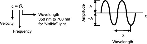
For visible light, the frequency is on the order of 1015 Hz. Photodetectors cannot respond to such rapid changes and thus generally indicate rms or mean values of power of the radiation.
Light can also be regarded as a stream of photons, individual particles of zero mass with an energy as in Figure 11.2.
Figure 11.2
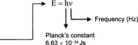
The energy of a photon depends on the frequency but is on the order of 10−20 J. Most detectors respond to large numbers of photons but there are a few that can provide a useful output for just one photon.
There is a difference between the measurement of radiant energy and that of light. The term light implies a human connection, and the measurement of visible light is called photometry. The human eye is a very common photometric detector.
Radiometry is concerned with the measurement of radiant energy independent of the type of detector used. A third field of radiation measurement is concerned with the quantum nature of light and is called actinometry—which arose from a study of the photochemical effects of light.
11.2. Measuring Light
Many units concerning light are in daily use but before we introduce them, we need to consider the definition of a solid angle, the steradian (sr; Figure 11.3).
Figure 11.3

Radiometric Definitions
- Radiant energy is energy received or transmitted in the form of electromagnetic waves and has the units of joules (J).
- Radiant power or flux is radiant energy received or transmitted per unit time in watts (W).
- Radiant flux density (irradiance) is the radiant power incident on a perpendicular unit area and has the units (Wm−2).
- Radiant intensity is the radiant power per unit of solid angle (W/sr).
Photometric Definitions
- The unit of luminous flux is the lumen (lm = cd.sr). Luminous flux is the radiant flux weighted by a spectral efficiency factor that characterizes the response of the human eye. The lumen is the human equivalent of radiometric power (W).
- The brightness of a surface is called the illuminance and has the unit lux and is the luminous flux per unit area (lx = 1 lm/m2). It is the human or photometric equivalent of radiant flux density.
- The luminous flux per solid angle is called the luminous intensity and is given the unit candela (cd). It is the photometric equivalent to radiant intensity.
Actinometric Definition
- Photon flux is the actinometric equivalent of radiant flux and is the number of photons impinging on a surface per second. Each photon has an energy = hv.
11.3. Standards of Measurement
The official SI base unit for measuring the luminous intensity of light is the candela. The candela is the only SI base unit that has its origins in the response of a human organ (i.e., the eye)—it is a photometric quantity. The candela is a base SI unit upon which lumens and lux are derived.
The candela is defined as the luminous intensity in a given direction of a source that emits monochromatic radiation of frequency 540 × 1012 Hz and has a radiant intensity of 1/683 W/sr in that direction.
The candela has become an important base unit due to the historical nature of measurements of light which involved the human eye as the detector. Early standards by which the response of a human eye were quantified involved candles, flames, and incandescent lamps. Human observers compared an unknown light source to a standard.
Modem methods utilize the response of a device (e.g., a photocell) that has spectral characteristics that are very close to that of a standard observer. Standard sources provide a way of calibrating photocells to be used in industry (Figure 11.4).
Figure 11.4

The most commonly used measurement of light intensity is not actually the candela but the illuminance or brightness and is typically given in lux. In a normal lecture room, the illuminance is about 300 lux. A bright summer's day: 20000 lux. In daylight, 680 lux corresponds to a radiant flux of about 1 Wm−2.
11.4. Thermal Detectors
In thermal detectors (Figures 11.5 and 11.6), incoming radiation results in a change of temperature of the sensor. The temperature of sensor is an indication of the magnitude of incident radiation.
Figure 11.5
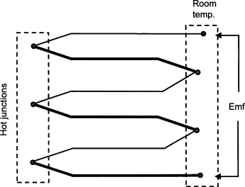
Figure 11.6

Temperature is usually measured with a thermopile, which consists of a large number of thermocouples in series. The sensitivity of a thermal detector using a thermopile with a surface area of 1–10 mm2 is typically about 10–100 V/W, with a time constant of about 10 ms.
The sensitive region of the detector is usually blackened so as to absorb the maximum amount of incoming radiation (Figure 11.5).
Still yet another type of thermal detector utilizes the pyroelectric property of certain ferroelectric materials. Incident radiation causes a change in the surface charge of a residually polarized ceramic. The effect can only be measured in a pulsed mode of operation and hence an AC amplifier is used to produce a reasonable output.
11.5. Light-Dependent Resistor
In a semiconductor, photoconductivity is a result of an increase in electrical conductivity due to impingement of photons on the semiconductor material. This increase can only occur if the incident photons have an energy hv > Eg where Eg is the energy gap between the valence and conduction bands (Figure 11.7).
Figure 11.7

Incident photons cause electrons in the valence band to be given energy hv and, if hv > Eg, valence electrons enter the conduction band, leading to an increase in the number of mobile electrons.
The increase in conductivity manifests itself as an increase in the current through the device for a given applied voltage and as such may be called a light-dependent resistor (LDR; Figure 11.8). For example, a popular material for LDRs is cadmium sulfide (CdS). CdS has a peak response at 600 nm, Eg = 2 eV and matches the frequency response of the human eye quite closely. In contrast, lead sulfide (PbS) (Eg = 0.4 eV) has a peak response at 300 nm.
Figure 11.8
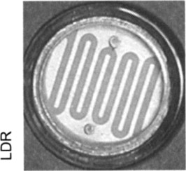
When an LDR is illuminated with a steady beam, an equilibrium is reached where the decay of electrons is matched by the excitation.
The ratio of the number of excited electrons to the number of incoming photons is called the quantum efficiency and is dependent on the probability of the number of elastic collisions between photons and electrons.
For a given frequency of incident beam, the number of mobile electrons created is a function of intensity of the beam. However, the conductivity of the material depends not only on the intensity of the incident radiation, but also upon its frequency. This is due to the filling of available quantum states.
11.6. Photodiode
A photodiode (Figure 11.9) employs the photovoltaic effect (Figure 11.10) to produce an electric current that is a measure of the intensity of incident radiation.
- Near the junction, concentration gradient causes free electrons from n side to diffuse across junction to p side and holes from p side to diffuse across to n side
- Resulting buildup of negative charge on p side and positive charge on n side establishes an increasing electric field Ed across the junction
- Current will flow in external circuit as long as photons of sufficient energy strike the material in the depletion region
Figure 11.9

Figure 11.10
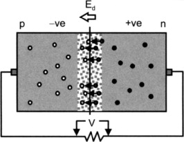
The area near the junction becomes free of majority carriers and is called the depletion region. When a photon creates an electron/hole pair in the depletion region, the resulting free electron is swept across the junction toward the n side (opposite direction of Ed).
Even though the photodiode generates a signal in the absence of any external power supply, it is usually operated with a small reverse bias voltage. The incident photons thus cause an increase in the reverse bias leakage current Io (Figure 11.11).
Figure 11.11

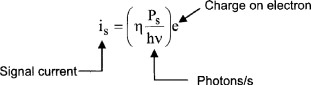
The reverse bias current is directly proportional to the luminous intensity. Sensitivity is on the order of 0.5 A/W.
11.7. Other Semiconductor Photodetectors
Avalanche photodiodes operate in reverse bias at a voltage near to the breakdown voltage. Thus, a large number of electron/hole pairs are produced for one incident photon in the depletion region (internal ionization).
Schottky photodiodes use electrons freed by incident light at a metal/semiconductor junction. A thin film is evaporated onto a semiconductor substrate. The action is similar to a normal photodiode but the metal film used may be constructed so as to respond to short wavelength blue or ultraviolet light only since only relatively high-energy photons can penetrate the metal film and affect the junction.
Phototransistors provide current amplification within the structure of the device. Incident light is caused to fall upon the reverse-biased collector-base junction. The base is usually not connected externally and thus the devices usually only have two pins. Increasing the light level is the same as increasing the base current in a normal transistor.
The PIN photodiode is a pn junction with a narrow region of intrinsic semiconductor sandwiched between the p- and n-type material. This insertion widens the depletion layer thus reducing the junction capacitance and the time constant of the device—important for digital signal transmission via optical cable.
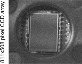
A charge coupled device (CCD; Figure 11.12) is an array of closely spaced photodiodes. Incident light is converted to an electric charge in each diode. A sequence of clock pulses transfers the accumulated charge to a digital output stream. For video applications, an image must be focused on the device using a lens.
Figure 11.12
11.8. Optical Detectors
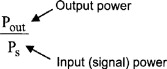
Optical detectors are characterized by
- Responsivity/sensitivity as shown in Figure 11.13
Figure 11.13
- Spectral response, sensitivity as a function of incident wavelength
- Detectivity D as shown in Figure 11.14
Figure 11.14

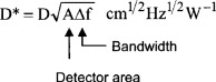
- Detectivity D*, independent of area and bandwidth, as shown in Figure 11.15
Figure 11.15
- Detectivity D**, independent of field of view, as shown in Figure 11.16
Figure 11.16

- Quantum efficiency,η, as shown in Figure 11.17
Figure 11.17
11.9. Photomultiplier
One of the most common applications of photomultipliers is for the detection of nuclear radiation. But, the device may be also used as the basis for detection of a wide range of phenomena that involve very low light output levels (e.g., chemiluminescent gas detector).
The light sensitive surface of a photomultiplier (Figure 11.18) consists of a thin film of an alkali metal which has a low work function, W. When a photon with energy E impinges on the metal, if E > W, then electrons are emitted from the metal (Figure 11.19). These electrons are accelerated by an applied potential (of about 200V) toward a dynode. An accelerating electron, when it strikes the dynode, has sufficient kinetic energy to eject two or more electrons from the dynode material.
Figure 11.18.

Figure 11.19

These two electrons are then accelerated through another 200-V potential to another dynode and thus cause four electrons to be ejected. This amplification may involve several stages of dynodes, each at a potential of 100–200V above the previous stage. Thus, the final electron current is sufficiently high to measure with conventional electronic equipment.
Amplification is thus done within the evacuated structure and may be as high as 106. Further, this amplification is done prior to the intrumentation amplifier input resistance and noise in the signal is thus reduced considerably. Dark current (due to thermionic emission at cathode) limits detectivity.
Note: A high-voltage power supply is needed to produce the required accelerating potentials at each dynode.