
We’ll go a bit deeper into Motion’s 3D world by adding a camera to a scene and then turning on and working with the various interface elements that allow us to navigate. We’ll also build a couple of “sets” in different locations in 3D space and learn how to quickly jump to different elements and adjust them. In Chapter 13, we’ll animate the camera to fly to each of these sets, completing the project.
Let’s begin by building a little project that will have three “sets.” A set is several related objects located in the same general region. Think of it like a Hollywood movie set: a set in Motion can have walls, a floor, a ceiling, and all sorts of actors and props inside it. For our purposes, we’ll keep the sets simple.
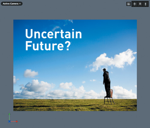
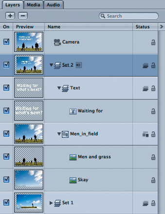
Our first set will consist of a Photoshop file with two layers and some text. To keep things organized, I’ve placed the image layers into one group, the text layer into another group, and both those groups into the overall group named Set 1 (FIGURE 12.1).

As we saw in the previous chapter, groups are 2D by default and need to be switched to 3D before the layers within them will interact with each other as they are moved and rotated in 3D space. But rather than clicking the 2D/3D icon for every group, you can convert them all to 3D at once simply by adding a camera. To do so, click the New Camera icon in the toolbar (FIGURE 12.2).
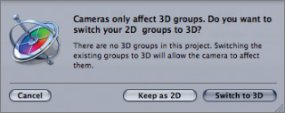
When you click the icon, a dialog appears. It lets you know that cameras won’t affect 2D layers, and it gives you the option to switch all your 2D layers to 3D. Click Switch to 3D to do it (FIGURE 12.3).
The camera appears in the Project pane at the top of the Layers tab, and all the groups’ 2D/3D icons have switched to 3D (FIGURE 12.4).

In the Canvas, our view of the scene hasn’t changed at all. This is because a new camera gets added to the same location as the default reference camera: the one through which you were already viewing the scene but couldn’t control. It’s almost as if you always were looking through a camera, but you just didn’t know it. But with an explicit camera, there are all sorts of interesting things you can do, like move the camera around or even move away from the camera and look at both the scene and the camera from a different viewpoint.
To make these changes, you need to know where the camera’s controls are, as well as how to get up and walk away from the camera.
When you add a camera to your project, three new sets of controls appear around the border of the Canvas: the Camera menu, the 3D View tools, and the Compass (FIGURE 12.5).
Audio Profile
BRIAN PSHYK
Senior Video Production Coordinator, www.samaritanspurse.ca
Brian Pshyk works for Samaritan’s Purse, the Canadian disaster relief charity. As senior video production coordinator, Brian finds himself on the front lines of major disasters world-wide, and Final Cut is right there with him. Visit the companion Web site and discover how he uses the powerful nonlinear editing tool.
By the way, if you don’t see these overlays, click the View button at the top right of the Canvas and make sure that Show 3D Overlays is selected, and that each of the five items underneath it is selected as well (FIGURE 12.6).

By using these overlays in combination with controls in the Canvas, the HUD, and the Inspector, you have complete creative control over the camera and layers in 3D space.
Let’s start with the 3D View tools at the top right of the Canvas. The three icons represent Pan, Orbit, and Dolly. The camera icon to the left of the tools indicates that, right now, these tools control the camera.
Dragging the Pan tool moves the camera left and right (along its X-axis) or up and down (along its Y-axis). Dragging the Orbit tool rotates the camera around its focal plane’s X and Y axes (more on this in a moment). The Dolly tool moves the camera forward and backward along its Z-axis, just as if you were standing behind the lens and walking straight forward or straight back. By using all three, you can move the camera anywhere in 3D space and look in any direction (FIGURE 12.7).

Here’s a super-handy tip: If you ever want to move the camera back to its original position and rotation, just double-click any one of the 3D View tools.
When you rotate the camera, the 3D grid appears in the Canvas. This grid represents the “floor” of your virtual world, and it is very helpful for keeping oriented as you add more layers and start to move both the layers and the camera around. The red line represents the horizontal X-axis and the blue line the Z-axis. They intersect at 0,0,0—the center of the virtual world.
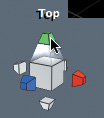
The three-legged guy at the bottom left of the Canvas is the Compass. As you can probably guess by now, the red axis is X, the green axis is Y, and the blue axis is Z. The Compass provides two functions. First, it lets you know exactly how you are oriented in the virtual world. See how the axes are aligned with the 3D grid axes? They will always match because the Compass always shows you the orientation of the world and not the orientation of the camera or layers in the world, both of which can change.
Second, the Compass lets you choose different points of view from that of the camera. In other words, it lets you step away from the camera lens and move other places in space so you can see both the scene and the camera. You do so by clicking the head of an axis. When you move the pointer over a head, the Compass tells you what the view is (FIGURE 12.8). Clicking the head then flies you to that view in a very smooth, elegant fashion (FIGURE 12.9).

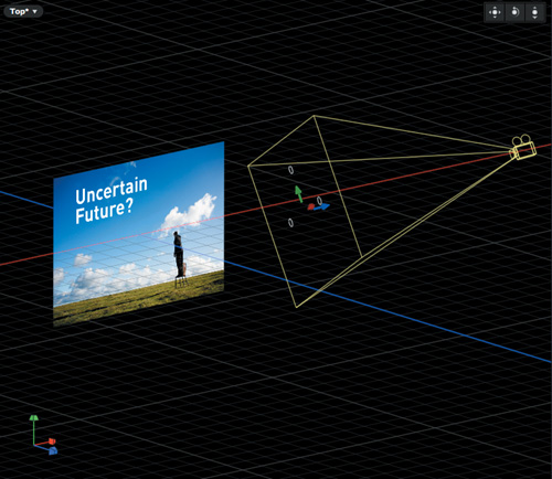
Each view from an axis is called an orthogonal view: It is a view directly along the X-, Y-, or Z-axis, and it doesn’t show any perspective. Notice how our text and image layers appear as a single thin white line. This is because they are both currently on the same plane, and they are each two-dimensional objects: Layers in Motion are 2D, arranged in 3D space. From this Top view, we can also see the camera and how it’s pointed at the layers. In addition to these orthogonal views (Top, Bottom, Left, Right, Front, and Back), the Compass also gives you an option to choose a Perspective view, which you can choose by clicking near its center.
The Camera menu at the top left now tells us we are in Top view. We could probably figure that out by looking at the Compass, but the Camera menu does provide a few other useful features.
Notice that the 3D View tools no longer have a camera icon next to them. This is because they now control our current view, which is not a camera view; changing them will change our view but will have no effect on the camera’s view of the scene (FIGURE 12.10).
In Figure 12.10, I used the Orbit tool to change the view of the scene. When you use the 3D View tools to modify a view, an asterisk appears in the Camera menu to let you know that this is no longer the default view. To reset the view, click the Camera menu, and choose Reset View (FIGURE 12.11).

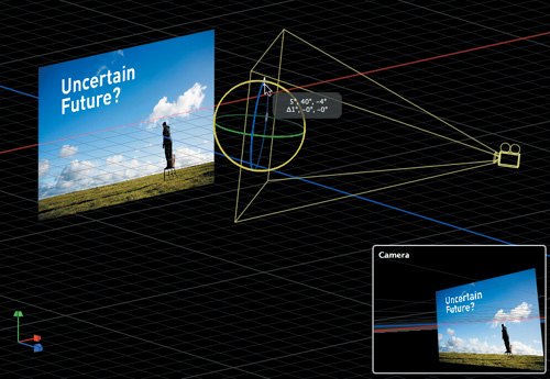
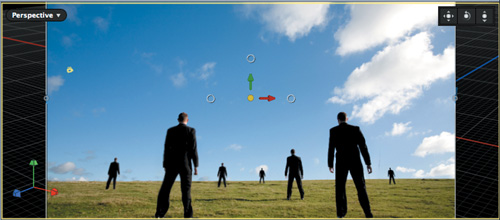
In Figure 12.10, notice the yellow lines extending from the camera. They connect to the corners of a rectangle. This is the focal plane of the camera. The anchor point of the camera is located at the center of this focal plane, where you see yet another set of red, green, and blue axes, along with three white circles, which are the rotation handles.
If you drag a rotation handle, the camera rotates around its focal plane. In other words, the center of the focal plane stays still while the camera swings around it, maintaining its “point of interest” as it rotates. As you drag, a window pops up to show you how the scene looks through the lens of the camera. This is the fifth and final 3D overlay, and it’s called the Inset view (FIGURE 12.12).
The Inset view is handy, but it pops up only when you are actively changing something. What if you want to look at two different views as you work? Or three? Or four?
At the top right of the toolbar, just under the Timing icon is the View Layouts pop-up menu. Click it, and you can choose from six different layouts that include from one to four separate viewports (FIGURE 12.13).
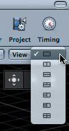
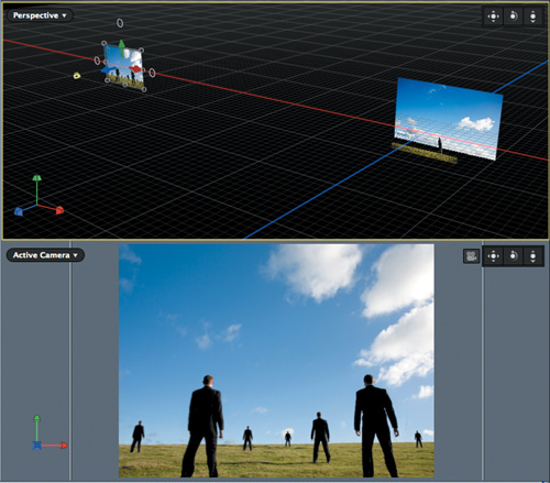
For example, the third one down gives you a split horizontal layout, with two viewports (see FIGURE 12.14).

You can set each viewport to its own view. Each viewport has its own camera menu, 3D View tools, and Compass (if you have turned those overlays on). Pressing Shift+Z fits a view to the viewport.
Note the yellow outline around the upper Perspective view in Figure 12.14. This outline tells you that this viewport is the active viewport. The active viewport is the one that will respond to keyboard shortcuts (such as Shift+Z to fit to window, or F, discussed a bit later), shows any motion when you play back the project, and will remain if you switch back to a single viewport layout. You make a viewport active simply by clicking anywhere inside it.
With our camera added, our overlays turned on, and our layout showing two viewports, we can now arrange our first set.
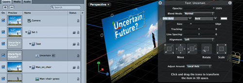
If you select the text layer, you’ll see the three axes extending out of its anchor point. Its blue axis points perpendicular to the layer, its green axis points up, and its red axis points to the right.
In the HUD, notice that the Adjust Around menu is set to Local Axis (Figure 12.15). This means that the axes for the layer are oriented relative to the layer: If you rotate the layer, the axes will move with it (FIGURE 12.16).

Local Axis is the default and is usually what you want when moving a layer so you can move it forward or back, up or down, and left or right relative to itself.
The Adjust Around menu allows you to change a layer’s axis to align with the World axis, or with your point of view, which is called the View axis (FIGURE 12.17).

The key here is to check the Adjust Around mode before you start moving layers with the Canvas or HUD controls so the layer moves in the way you expect. Note that the Inspector controls are always based on the World axis.
Let’s go back to Local Axis mode and rotate the text back to 0 degrees using the Inspector. Now we can use the first HUD control to drag the text forward in Z-space, then down and over a little to reposition, using the Active Camera view as our guide.
Why are we doing this? Because with the elements spread out from each other in Z-space, you’ll see them shift in relationship to each other as you animate the camera to move around the set (FIGURE 12.18). In other words, because it will look cool.

Audio Profile
Proprietor, Primarily Art Stuff, www.tomdukich.com
Tom Dukich is an artist specializing in multi-media and video. Visit the companion Web site to see how he uses Final Cut in his art.
Of course, with the text layer closer to the camera, it appears larger, so we’ll need to scale it down to have it look like it did when it was farther away.
But wait, there’s actually a way to do that automatically! Let’s try it out with the sky layer. If you select the sky layer and use the HUD to push it back in Z-space, it appears smaller. In the Active Camera view, we can now see black around the edges—not so nice (see FIGURE 12.19).

We could scale it up enough to fill the frame again, but instead, undo the move, then before dragging in the HUD’s first control, hold down the Command key. Take a look at the Inspector as you drag (see FIGURE 12.20).
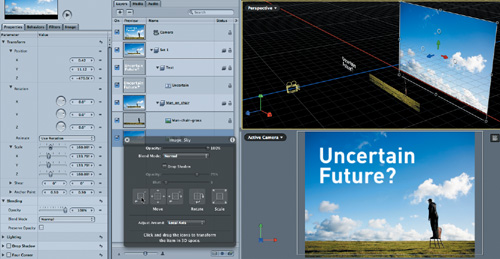
The Scale parameter is changing as you drag! In fact, Motion is changing the scale dynamically, just enough to keep the layer looking the same size from the camera’s point of view.
If you now use the 3D View tools in the Active Camera view to orbit the camera, you’ll see the man on the chair shift in relationship to the clouds behind him, creating a sense of depth.
With the first set arranged, let’s drop in the second one. The idea is that we’ll want to “fly” the camera from the first set to the second. We could put it anywhere in space, but let’s say we want it off to the left.
The easiest way to add objects to a different location is to first move the camera to that location, then add them to the Active Camera view. Let’s try it.
First, we’ll close our Set 1 group to keep the Layers tab tidy. In the Perspective view, we’ll dolly way out and over so we can see the first set and lots of space to the left. Then we’ll select the camera, and in the Perspective view, drag the red handle to move it to the left (FIGURE 12.21).

The camera faces the same direction, since we didn’t rotate it at all, but now it looks out at a vast expanse of nothingness. Now, here’s the critical part. If you drag an object directly to a viewport in the Canvas, it will be positioned in 3D space to face that view. For example, if you drag to the Perspective view, the image faces that view (FIGURE 12.22).
This is not what we want. And if you drag the image to the Layers tab, it gets positioned in the center of the virtual world; in our case, right in the middle of Set 1 (FIGURE 12.23).

However, we want it over to the left, where the camera is. So instead, drag the image for the second set from the File Browser directly to the Active Camera view in the Canvas (FIGURE 12.24). If the file is a multi-layered Photoshop file, as in our case, wait before letting go and choose to Import All Layers so you can manipulate them separately.
Let’s add some text and then spread out these elements. Select the Text tool, click in the Active Camera view, and type “Waiting for what’s next?”. In the Layers tab, put the text in its own group, and name the group containing the text and the image layers “Set 2” (FIGURE 12.25).
This process of first moving the camera and then adding elements directly to the Active Camera view makes the process of building multiple sets in 3D space quick and easy.
Now, to spread out the layers of the Set 2 group, it would be helpful to zoom in closer in the Perspective view. You could use the 3D View tools to pan, orbit, and dolly to where you want, but there’s a quicker way. Make the Perspective view active, and then in the Layers tab, press the Command key, then select both the Set 2 group and the Camera. Now click the Camera menu and choose Frame Objects, or simply press the letter F (FIGURE 12.26).

Motion moves the view to precisely frame just the selected objects. Very nice!
Now it’s just a matter of selecting the text and each layer in the image and Command-dragging the first HUD control to move the layers in Z-space to scale them at the same time in order to keep the composition aligned, as we did with the first set. You will probably still need to tweak the position of the elements due to the parallax shift. If an object isn’t in the center of the frame, as it moves towards you it also moves off to the edge (FIGURE 12.27).

For the final set, let’s push the camera straight forward through Set 2 (using the camera’s blue Z-axis handle in the Canvas), then move the camera up (with the green Y-axis handle). Now, deselect everything, and in the Active Camera view, add some text with the Text tool. Since nothing is selected, the text gets created in its own new group. Add a rectangle shape around the text, use the HUD to turn on the Outline and turn off the Fill. Set this frame back from the text a little in Z-space. Name the new group Set 3 (FIGURE 12.28).

Audio Profile
SABRINA NELSON
Educator
Sabrina Nelson, a college professor and editor, discusses the challenges in teaching college students Final Cut Studio and the advice she gives them on obtaining jobs in the industry. Visit the companion Web site to hear more.
With all sets constructed, close the groups, click below them to deselect everything, then in the Active Camera view, double-click any of the 3D View tools to reset the camera to its default location at the center of the virtual world. With the Perspective view active, press F to frame all the sets (FIGURE 12.29).

The F key is a very powerful way to quickly frame an entire scene or selected layers in a scene. If you use the F key in the Active Camera view, it moves the camera; in other views, it just changes the view.
By using the 3D overlays such as the 3D View tools and the Compass, in combination with the onscreen controls and the HUD, you can quickly build sets and move to and adjust any part of a 3D scene.
In the next chapter, we’ll look at some options for animating the camera to move from scene to scene, and explore some other ways to quickly select and adjust elements in 3D space.