
Now we get to the (really) fun stuff: flying a camera around in 3D space. We’ll start where we left off in the previous chapter—with three sets arranged in 3D space—and then look at how to use keyframes to animate the camera to fly from set to set.
The project we’ll use is a short promo for a fictional business news show called “Future News.” It consists of three virtual sets—groups of layers each positioned in a different place in 3D space. Using the Camera menu at the top left of the Canvas (discussed in the last article) to go to Perspective view allows you to see all three sets, as well as the location of the camera (FIGURE 13.1).

Audio Profile
Owner, Image/Worxx, www.thirdeye.at
Florian Gintenreiter, based in Austria, is a guerrilla filmmaker who just recently completed a horror/western film shot on HDCAM and finished totally in Final Cut Studio. He shares his experiences in this interview on the companion Web site.
Project Files
The project files and the content used in this chapter are available for download. If you’d like to follow along, please visit the book’s companion Web site.
So what are we looking at? The first two sets in this project each consist of a two-layer Photoshop file and a text layer, all spread apart from each other along the world’s Z-axis. The third set consists of a rectangular blue frame created with a shape and a text layer.
In addition to the layers being spread apart in Z-space, the sets themselves have been separated from each other in X-, Y-, and Z-space. To see this, use the Compass at the bottom left of the Canvas to go to Top view; you’ll see each set is located differently in X and Z (FIGURE 13.2). Then go to Front view to see how Set 3 is higher in Y (FIGURE 13.3).


Now, when building and arranging your sets in 3D, I have three rules that can help make your first camera animation process go smoothly.
In other words, have the camera animation start at the very center of the virtual world. To check the location of the camera in this project:
Use the Camera menu to go to the Active Camera view.
Select the camera in the Layers tab.
Go to the Properties tab of the Inspector.
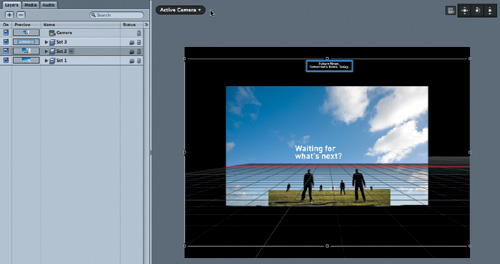
You’ll see that our first set is visible through the camera lens, and that the camera is positioned at 0,0,0 with no rotation (FIGURE 13.4).

Why is it useful to set up your scene in this way? No matter where you move the camera, you can always move it back to perfectly frame the first set if you reset it, which you can do by clicking the hooked reset arrow next to the Transform properties in the Inspector or double-clicking any one of the 3D View tools in the Canvas.
As you saw in the Perspective, Top, and Front views, each layer of each of the three sets is flat to the X-Y plane. And the groups the layers are contained in are also oriented in the same way. Also, notice in FIGURE 13.5 that the Adjust Around option in the HUD is set to Local Axis, and that each of the three groups are oriented with their Z-axis (the blue arrow) aligned to the world’s Z-axis (the blue line on the grid).

There are many times you’ll want to break this rule for creative purposes, but if you don’t need to change the orientation of layers in a set, or of a set itself, it will make the camera animation much easier to execute if your sets face the same direction along the Z-axis.
The anchor point is located where the three colored axis handles intersect. In FIGURE 13.6, you can see it is inside of the bounding box for each of the selected groups.

Since the anchor point for a layer, and therefore a group, is located by default in the center of the layer, you may think to yourself, why would I have to worry about this? Well, here’s the issue: if you move the camera, then add a layer (such as an image, a video clip, or some text) to the Active Camera view, the object gets added right at the focal plane of the camera (as we discussed in detail in Part 2). This is very handy for quickly building sets in other parts of 3D space, but when you do so, the anchor point for the group containing those layers remains at 0,0,0, the center of the virtual world.
So what? Well, if you attempt to rotate or scale the group, it will rotate or scale around its anchor point, which could be very far from the layers in the group, thus creating quite unexpected results. And, more pertinent to this discussion, there is an incredibly useful behavior for animating the camera that just won’t work correctly if the anchor point of the group is located somewhere away from the group.
To summarize: In order to make the process of animating the camera to move from set to set go as smoothly as possible, you need to do the following:
Build your first set at the center of the virtual world (at 0, 0, 0).
Have all your sets face the same direction.
If needed, move the anchor point for each group inside the group.
If you follow these three rules as you start to work with cameras, you’ll understand the implications when you intentionally break them later on.
With our project properly prepared, we can now get to the good stuff—putting the camera into motion.
Motion uses two distinct approaches to animation: keyframing and behaviors. With traditional keyframing, you set specific values at specific points in time and then determine how Motion changes, or interpolates, the value between any two keyframes. Behaviors are procedural animations, which means you apply them, make a few setting changes perhaps, and away they go; their own internal mathematics take over.
You can use either of these approaches, or a combination of both, to animate anything from a bouncing ball to the blur of a background to the speed of a video clip. Which one you use is really a matter of your specific goals: generally speaking, behaviors are very fast, and keyframing gives you more precise control. Behaviors allow you to create animation that would be time-consuming or in some cases downright impossible with keyframes (such as simulation behaviors); keyframes let you create very precise animation, particularly when it comes to coordinating the timing of the animation of multiple objects.
When it comes to animating cameras, you have the same two options: keyframing or behaviors. In this chapter, we’ll explore using keyframes; in the next, we’ll work with behaviors.
When you create animation with keyframes in Motion, you have two options: you can set the keyframes manually, or you can use the Record button to record the keyframes automatically. We’ll use both approaches together.
The goal for this project is to start with the camera facing Set 1, move it to view Set 2, then finally move it to view Set 3. To start, you should be in Active Camera view, and you should see the first set as shown in Figure 13.4. Double-click any 3D View tool to reset the camera just in case.
Now, you’ll need to consider the timing of the animation. The full project is 10 seconds long, which you can determine by looking at the Duration field at the bottom right of the Canvas (see FIGURE 13.7).

Let’s have the camera view Set 1 for 3 seconds, then move it to Set 2 over the course of one-half of a second (or 15 frames), where it will then remain for 3 seconds before taking 15 frames to move to Set 3, where it will remain until the end of the project.
Since the camera will stay still for the first 3 seconds of the project, you’ll need keyframes at the beginning and end of this time span. To add the keyframes, follow these steps:
Move the playhead to the start of the project. Click the Record button at the bottom of the Canvas to turn on recording.
You want to set a keyframe at the first frame. But when recording is turned on, keyframes get recorded only when you change a parameter value. Since we don’t need to change anything here, how do we set a keyframe?
One option would be to move the camera just a little and move it back. That action would set a keyframe, but you might not move the camera back to exactly where it was, so it’s not a very precise method.
Another option is to set our first keyframe manually. Whether recording is turned on or not, you can always set keyframes manually in either the Inspector or the Keyframe Editor.
With the camera selected, select the Properties tab of the Inspector, click the Animation menu for Position (the small dash to the right of the word Position), and choose Add Keyframe (FIGURE 13.8).
Solid diamonds appear in the Animation menu for Position X, Y, and Z, indicating there is now a keyframe for all three of these parameters at the current playhead location (FIGURE 13.9).
It’s a good practice to set keyframes for both the camera’s position and its rotation (also called its orientation) in case you decide to rotate it later. Go ahead and set a keyframe for the Rotation values as well using the same method. Or, you can press and hold the Option key while clicking the dash. It may not seem like much, but when you are adding a lot of keyframes, you’ll be glad you know this shortcut.
OK, our first keyframe is set. Now move the playhead forward 3 seconds. By the way, you don’t need to click in the Current Time field; you can just type +3. (plus 3 period) and press Return to move the playhead. (This trick won’t work if the Timeline is open. Instead, the selected layer will move over 3 seconds, so be careful!).
Notice in the Inspector that the diamonds in the Animation menu are now hollow: This indicates that there is at least one keyframe somewhere for the parameter, but there isn’t one at the current playhead location (FIGURE 13.10).
Because you want the camera to remain still from the beginning of the project to this point, facing Set 1, you can manually set position and rotation keyframes here just as we did at the beginning of the project.
Now type +15 and press Enter to move forward 15 frames. This frame is where you want the camera to arrive at Set 2.
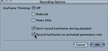
Since recording is turned on, as soon as you change the camera’s position and/or rotation, keyframes will be set automatically. In fact, if you change any parameter of any layer, keyframes will be set, which can be dangerous. So before you do anything, let’s make a quick change to how Motion sets keyframes.
Choose Mark > Recording Options. Select the “Record keyframes on animated parameters only” checkbox (see FIGURE 13.11).
Now if you change the camera’s position or rotation, keyframes will still be recorded, since these parameters already have a keyframe. But you won’t accidentally set keyframes if you decide, for example, to tweak the layout of the layers in one of the sets.
Click OK to close the Recording Options window.


Now, back to business: you want to move the camera to the Set 2 group in order to set the next keyframe. But how do you know where to move the camera, and what do we use to move it? There are many different ways to move and rotate the camera: by using the HUD, the 3D View tools, the Inspector, or even the on-screen controls (if you aren’t in an active camera view). You can split the Canvas into two separate viewports so that you can see the camera’s point of view in one viewport while you manipulate the camera in the other viewport.
However, you aren’t going to do any of that here. Instead, you’ll take advantage of an incredibly handy command called Frame Objects.
First, in the Layers tab, select the Set 2 group.
Now, in the Camera menu, choose Frame Objects—or better yet, just press F (FIGURE 13.12).
The camera suddenly shoots over to Set 2. You can see the bounding box for the group just touches the edge of the Canvas; in other words, the camera has perfectly framed the selected object (FIGURE 13.13).
Frame Objects is a great tool to quickly move the camera to a specific layer or group of layers. And, if recording is turned on, keyframes will be set at the playhead. One thing to note: the camera will not change its orientation when it moves to frame the objects. In other words, it will not rotate, even if the objects it is framing are rotated at an angle. Thus the reason for my second rule in preparing your project: if you orient all your layers to face the same direction, you can use the Frame Objects command to very quickly move the camera to an object and set keyframes, and you’ll be sure to be facing the layers correctly.
However, we still have some work to do: there’s a lot of empty black space around our second set. This is because the layers in this group have been spread out in Z-space, and the bounding box of a group expands to contain all of the layers inside it.
So, click-drag the Pan and Dolly controls in the 3D View tools to move the camera forward and properly frame the group (FIGURE 13.14).
Don’t use the middle Orbit control because right now you don’t want to change the rotation of the camera. Although there are many different ways to move the camera, the nice thing about the 3D View tools is that the camera doesn’t need to be selected in order to use them.
Finally, keyframes didn’t get set for the rotation of the camera because you changed only its position. So select the camera, and in the Properties tab of the Inspector, Option-click the Rotation animation menu to set keyframes for Rotation X, Y, and Z (FIGURE 13.15).


Creating the rest of the animation involves repeating the same process, so I won’t belabor it. Here’s what to do:
Type +3. (plus 3 period) to move the playhead forward 3 seconds, to 6:15.
In the Properties tab, Option-click Position and Rotation for the camera to set manual keyframes. (Remember, we want the camera to remain still and facing Set 2 for these 3 seconds.)
Move the playhead forward 15 frames, to 7:00.
In the Layers tab, select the Set 3 group and press F to frame it.
If needed, use the 3D View tools to reframe the set in the Canvas (FIGURE 13.16).
Add a manual keyframe for rotation.

That’s it! Play back the project to check out the animation.
It’s likely that you’ll see some strange behavior while the camera is on the second set: Rather than staying still, the camera dollies back and then shoots back in. To see what’s going on, make sure the camera is selected, then follow these steps.
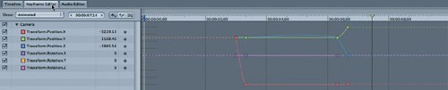
Press F6 to open the Timing pane, and select the Keyframe Editor (FIGURE 13.17).
Note how the blue Transform.Position.Z line, rather than staying nice and flat, rises a little between 3:15 and 6:15? You don’t want this parameter to change values between these two keyframes, so you’ll need to change its interpolation.
Option-click the checkbox next to the Transform.Position.Z parameter to solo it in the Keyframe Editor. This action gets rid of all the other curves so you can focus in on just this one parameter.
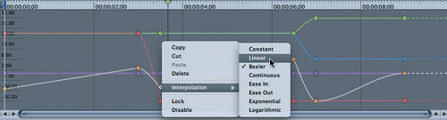
Then, right-click or Control-click the third keyframe and choose Interpolation > Constant (FIGURE 13.18).
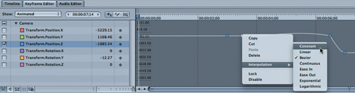
Constant interpolation means the value won’t change between the two keyframes. Linear would work here as well. Now play the project.
It plays correctly now, but the animation is a bit dull: When the camera isn’t racing from one set to the next, it’s sitting dead still. It would be more interesting to have it rotate slightly while looking at a scene, thereby revealing the depth of the different layers, wouldn’t it?
We can accomplish this quite easily. The key is to make sure we are parked directly on a keyframe before rotating the camera.
With the camera selected and the Properties tab visible, press Home to move the playhead to the beginning of the project.
In the Properties tab, check to make sure you see solid diamonds, which will confirm that you are, in fact, parked on a keyframe.
In the Inspector, drag left in the Rotate Y value field to rotate the camera just slightly to the left. In the Canvas, you’ll likely expose the edge of the sky.
Open the Set 1 group, select the Sky layer, and increase its scale to fill the Canvas. You may need to do the same with the Man-chair-grass layer (FIGURE 13.19).
The project now begins with the camera rotated slightly to the left on its Y-axis.
Close the Set 1 group, select the camera, and press Shift+K to move to the next keyframe, at 3:00. (By the way, this is the same keyboard shortcut as Final Cut Pro; moving backward is Option+K, also the same.)
Use the Inspector to rotate the camera slightly to the right on the Y-axis. The camera will now rotate, or “sweep” over Set 1 before moving on to Set 2.
To finish, you just repeat the same process for Sets 2 and 3: Press Shift+K to jump to the next keyframe, adjust the starting camera rotation, move to the next keyframe, adjust the ending camera rotation. Adjust the scale of any layers in the set that no longer fill the Canvas.

You can use the 3D View tools or the HUD instead of the Inspector if you want to slightly pan, orbit, and/or dolly the camera, but if you want to precisely change just one axis of position or rotation, the Inspector is your best bet.
For Set 3, you’ll need to add ending keyframes for position and rotation. Rather than adding them at the very end of the project, add them at 9 seconds so the camera will sit still on the phrase for the last second. Make the ending text phrase start off-center, then rotate it to perfectly face the camera.
To tweak the camera rotation, you might want to change the keyframe interpolation to linear so you won’t see a slight delay as the camera starts up its rotation (FIGURE 13.20).
That’s the basics of animating the camera with keyframes. By using keyframe recording and the Frame Objects command, you can very quickly rough in your animation, then clean it up by changing the keyframe interpolation, adjusting camera angles at keyframes, and scaling layers.
As we have now demonstrated, you can animate the camera in a very specific manner using keyframes. There’s much more to using keyframes than we have been able to cover here, but hopefully this will get you started.
As you’ll see in the next chapter, behaviors offer an alternative approach to animating the camera, and they allow for a variety of interesting and creative options.