
where B is the proportionality constant and n is the exponent. The values of the constants a and n depend on the joint configuration, type of lubricant and coating used. The values of n for bare, coated and lubricated aluminum-to-aluminum and aluminum-to-copper connections were found to vary between 0.1 and 1.0. The effect of contact load on the contact resistance of aluminum bus bar connections is shown in Figure 5.75 [143]. For practical purposes, the problem of adequate contact force for a joint of satisfactorily low initial resistance can be simplified by considering the applied force as uniformly distributed over the apparent contact area. Naybour and Farrell [71] have shown that, provided the initial stress at 20°C is less than 60 N/mm2, stress relaxation is not likely to cause significant contact deterioration on aluminum conductors if the initial load is 2000 N. This value of contact load is considered as a practical minimum although added efficiency can be realized with higher contact loads which can maintain points of intimate contact even with some stress relaxation.
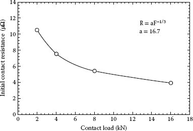
FIGURE 5.75
Effect of contact load on the contact resistance of aluminum-to-aluminum bolted joints.
It should be emphasized for bolted joints that the use of contact force as an indicator of a satisfactory joint assembly is impractical. Instead, tightening torque is almost exclusively used in practical situations. An empirical relationship commonly used to relate the tightening torque to the applied force generated by the bolt in a joint is given:
(5.32) |
T—Tightening torque (Nm)
D—Bolt diameter (m)
K—Constant (“nut factor” – dimensionless)
F—Contact force (N)
The “nut factor” K is greatly dependent on the coefficient of friction, finish and lubrication of the threads and other bearing surfaces. For specified conditions of finish and lubrication there is considerable variation in this relationship. Also both the tightening torque must be specified and the rate of tightening must be controlled. The rate of relaxation from cold flow of aluminum conductor is quite large under the pressures encountered in most bolted connectors. Hence a slow rate of application of torque will result in more relaxation being taken up before the final installation torque is reached. Although continuous torque application produces more rapid failure, a stepped application of torque was selected as the standard of tests. Continuous torque application was considered impractical for a standard procedure since multi-bolt connectors must be installed by tightening each bolt in turn by steps.
Tightening torques depend upon the contact pressure required for the particular busbar application. The amount of pressure for a given torque value varies over a wide range; depending upon whether threads are dry, lubricated, hot galvanized, or otherwise treated. From the standpoint of the intensity of the bolts, a maximum tightening torque equal to 95% of the yield strength of bolt is recommended. Hence, it is essential to maintain the tightening torque within this limit since upon exceeding it, the busbar will undergo plastic deformation which, in turn, will increase the stress relaxation and creep and thus cause loosening of a joint. The end result is an increased contact resistance and temperature causing the eventual joint to fail. A recap of the tightening torques specified by different manufacturers for bolting different power equipment reveals a great diversity in the recommended torque values. For instance, the range of tightening torque for a 12.7 mm (½ in.) diameter bolt is 50–80 Nm (35–60 lb-f). Hence, the forces generated by these torques may exceed the yield strength of certain bolt material.
To illustrate the importance of tightening torque and also the “nut factor” K, let us calculate the stresses generated by the torque range 50–80 Nm (35–60 lb-f) in 12.7 mm diameter (½-13 in.) bolts made of silicon bronze and stainless steel 304 and 316. The results are shown in Table 5.16. From this table it can be inferred that for lower values of “nut factor” K (K = 0.15) certain bolt materials cannot sustain the forces generated by the applied tightening torque and would deform plastically. The lower values of the “nut factor” K (K = 0.15) are generally attributed to the effect of lubrication on the coefficient of friction. Hence, it appears that same tightening torque may induce much higher force in the lubricated than in non lubricated bolts. This is very important since, it may be contended, that the use of contact aid compounds may adversely affect the mechanical integrity of a bolted joint by exceeding the permissible force limits in the bolts. The habit of common contact aid compounds (see also Section 5.6.5) did not produce any significant increase in the contact forces neither in the bolts nor in the joint. However, when boundary lubricant, such as Mo2S (K = 0.15), was used, much higher force was generated in the bolt. Table 5.17 shows the range of the “freak factor” when jointing was made with dry bolts and also when lubricated with the contact aid compounds and boundary type lubricant. It appears that there is a very small difference between the values of the “nut factor” K for dry bolts and those lubricated with the contact aid compounds. The effect of lubrication that is the “nut factor” K on the contact force generated in bolted joints is shown in Figure 5.76.
TABLE 5.16
Characteristics of Bolt Materials and Calculated Forces in Bolts Generated by Tightening Torques for Different Values of “Nut Factor” K
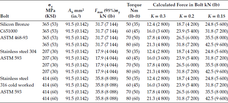
σy—Yield stress,
Ab—Bolt cross section,
Fmax—Maximum force supported by the bolt.
TABLE 5.17
Values of “Nut Factor” When Dry and Lubricated Bolts were Used for Assembling the Bolted Busbar Joints
Nut Factor |
Dry Bolts |
Contact Aid Compounds |
Boundary Lubricants |
K |
0.20–0.22 |
0.19–0.21 |
0.15–0.16 |
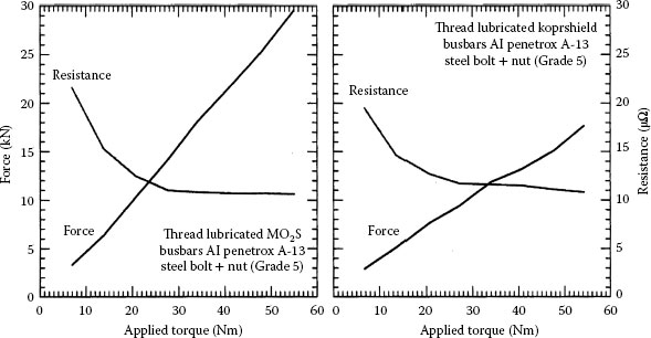
FIGURE 5.76
Effect of the “nut factor” on the contact force generated in bolted joints.
5.5.3 Mechanical Contact Device
Although a bolted type connection is widely used method of joining aluminum and copper conductors, there are doubts concerning its reliability under the operating conditions, owing mainly to the fact that when two dissimilar metals are used, the difference in their physical, mechanical and metallurgical properties results in difficulties to arrive at a satisfactory joint. In order to shorten this problem, various palliative measures in the design and joint configuration were considered. One of these is the use of suitable mechanical contact devices combined with appropriate tightening of a joint, thus ensuring that all members of a joint remain within their elastic limits under all anticipated operating conditions.
To illustrate the importance of these mechanical contact devices, let us examine the tensions generated in a bolted joint with no current passing through the joint. The joint configuration consists of two aluminum or copper busbars measuring 38 × 12.7 × 250 mm, two 38 mm diameter flat washers and a 12.7 diameter steel or bronze bolt. During assembling, the bolt is subjected to a simple tension while the busbars to compression. The “nut factor” used for calculating the forces generated in the bolt by applying torque was K = 0.2. The stress distribution in the busbars under the washer was assumed to be uniform. The calculation results are shown in Table 5.18. If the busbars were made of aluminum EC-0, the stresses generated by tightening torque of 60 Nm (45 lb-f) would exceed their yield strength which is 28 MPa (4000 PSI). It should be pointed out, that the above calculations were made assuming a uniform stress distribution in the contact zone under the washers. However, since the real contact area is much smaller than the apparent contact area, the stresses generated at the a-spots, where the actual contact is made will much higher.
TABLE 5.18
Stresses Generated in the Bolt and Busbar Conductors
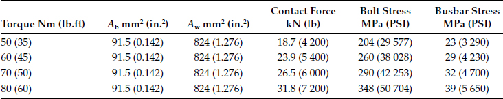
Ab—Bolt cross section,
Aw—Apparent contact area under washer.
The heating and cooling of a bus joint as the result of normal changes in electrical load cause corresponding increases and diminutions in the thickness of the bolted joint, varying in magnitude with the thermal expansion coefficient of the material, Moreover, the bolts are usually not heated by the current in the conductors to the same extent as the conductor itself. The result may be a temperature differential of 10°C or more between the bolt and the conductor, which tends to narrow over a period of time. During the hot portion of the load cycle, the differential expansion of the bus conductor and the bolts add additional stresses to the original stresses in the conductor and the bolt. The increase in the stresses in the busbar conductors (Fsup) and the bolt are is proportional to the temperature rise (ΔT) and is given as
(5.53) |
αa—Coefficient of thermal expansion of the busbar conductor
Ea—Elastic modulus of the busbar conductor
αb—Coefficient of thermal expansion of the bolt
t—Thickness of the washer
Ab—Bolt cross section
a—Thickness of the busbar conductor
Eb—Elastic modulus of the bolt
Aw—Apparent area under the washer
Aa—Apparent contact area of overlapping joint
For the joint assembled initially at 55 Nm (40 lb-f), that is, contact force of 22 kN (4800 lb) the calculated additional force, generated in the busbars and the bolt when the joint temperature increased to 120°C is given in Table 5.19. The coefficients of thermal expansion used to calculate the additional force in the joints were: steel—11, aluminum—23.6 and copper—16.5 (K−1 × 10⁻⁶). The results shown in Table 5.19 clearly show that the stresses and the resulting deformation are much greater for aluminum than for copper busbar conductor for the same temperature rise. This illustrates the importance of maintaining reasonably constant pressure in bolted joints during the heating and cooling cycles of operation. Hence, the higher yield strength and better creep characteristics of busbar conductors and the use of suitable mechanical contact device are very important in order to obtain stable electric joints. Recommended tightening torques for bolted joints assembled with different bolt sizes are given in Table 5.20.
TABLE 5.19
Increase in Stresses in the Bolt and the Busbar Conductors Due to Temperature Rise of 120°C
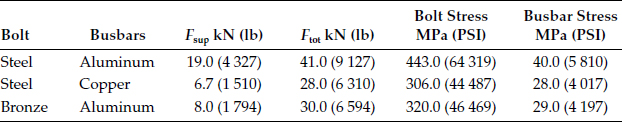
TABLE 5.20
Recommended Tightening Torques for Bolted Joints Assembled with Different Bolts Sizes
Bolt |
Tightening Torque |
||
M |
Nm |
Kgf.m |
lbf.ft |
10 (3/8) |
35–50 |
3.5–5 |
26–37 |
12 (1/2) |
60–85 |
6–8.5 |
45–63 |
16 (5/8) |
150–200 |
15–20 |
110–150 |
5.5.4 Disc-Spring (Belleville) Washers
The mechanical integrity of the bolted connector is strongly affected by the joint configuration, which can differ according to the mechanical device used. The combination of a disc-spring (Belleville) and thick flat washers was found to assure the most satisfactory mechanical and electrical integrity of bolted joints under current-cycling and stress relaxation conditions [58]. One of the most important characteristics of disc-spring washers is their ability to elastically absorb deformation caused by an outside load. In order to comply with the space limitations imposed by the geometry of a bolted joint, disc-spring washers have to be as modest as possible and made from materials having a high tensile strength and high elastic limit. These materials should also have high dynamic fatigue resistance, sufficient plastic deformation ability exceeding the elastic limit to permit manufacture of cold worked springs as well as to minimize failure of springs under sudden and sharp load changes. The effect of different types of mechanical contact devices on the performance of bolted aluminum-to-aluminum joints under current cycling and stress relaxation conditions was investigated by Braunovic [58,130]. It was demonstrated that the mechanical integrity of the connector is strongly affected by the joint configuration, which differs according to the mechanical device used. The combination of a disc-spring (Belleville) and thick flat washers assured the most satisfactory mechanical and electrical integrity of bolted joints under current-cycling and stress relaxation conditions; see Table 5.21.
TABLE 5.21
Forces Generated in the Busbar Conductors without and with the Disc-Spring (Bellevile) Washers
Bolt |
Busbars |
Force in Busbars without Disc-Spring Washer kN (lb) |
Force in Busbars with Disc-Spring Washer kN (lb) |
Steel |
Aluminum |
19.0 (4 327) |
1.2 (276) |
Steel |
Copper |
6.7 (1 510) |
0.4 (95) |
Bronze |
Aluminum |
8.0 (1 794) |
0.8 (173) |
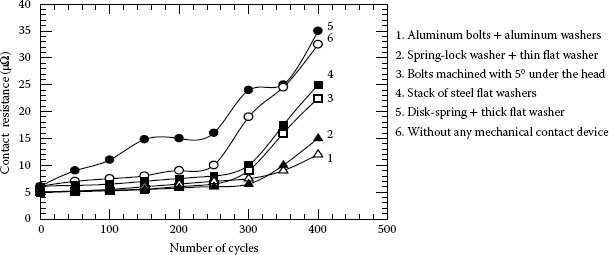
FIGURE 5.77
Effect of different mechanical contact devices on the contact resistance of a bolted joint under current-cycling conditions.
Disc-spring washers are generally made of spring steel such as high-carbon, chrome-vanadium, chrome-vanadium-molybdenum, tungsten-chrome-vanadium and stainless steels. However, other resilient materials, such as silicon and phosphor bronze, beryllium copper, inconel and nimonic can also be employed. Effect of different mechanical contact devices on the contact resistance of a bolted joint under current-cycling conditions is illustrated in Figure 5.77. Figure 5.78 shows joint configurations for jointing aluminum or copper busbar conductors. In all cases, it is recommended to use flat washers at least 3–4 mm thick. With steel bolts, disc spring washers with a high spring constant and flat washers with thickness at least twice that of the disc-spring washer should be applied.
One method of avoiding failures owing to differential thermal expansion consists of using aluminum alloy bolts. Since the coefficients of expansion of the aluminum conductor and the bolts are essentially the same, high contact pressure is held during both heating and cooling cycles. The modulus of elasticity of aluminum alloy bolts is about one-third that of steel bolts. Thus a large amount of “spring-follow” is provided in the bolts. Since the compressive stress in a bolted joint is concentrated under the head and nut of the bolt, aluminum bolts made of alloys with yield strength of 400 MPa and tensile strength of 470 MPa, such as 7075 T-72 alloy, are recommended. Equally, for jointing the copper busbars, bolts made of a high-strength bronze (everdur) are preferable over that of steel. Aluminum alloy and bronze bolts are nonmagnetic and, therefore, not subject to heating from hysteresis losses in ac fields, as is the case with steel bolts. Advantages and disadvantages of mechanical connectors are given in Table 5.22. Another important factor affecting the performance of bolted joints is the selection of the bolts. The use of steel bolts in aluminum and copper bolted joints without mechanical contact devices such as disc-spring (Belleville) to compensate for the difference in the thermal expansion between aluminum, copper and steel, may result in thermoelastic ratcheting which, in turn, will adversely affect the joint integrity and performance. The beneficial effect of spring washer is shown in Figure 5.79 as a function of time and under static and dynamic operating conditions. In the case of static operating conditions the loss of relative contact force was simply measured as a function of time. However, in the case of dynamic operating conditions, the joint were subject to current cycling and the remaining contact force was measured at the preselected time intervals.
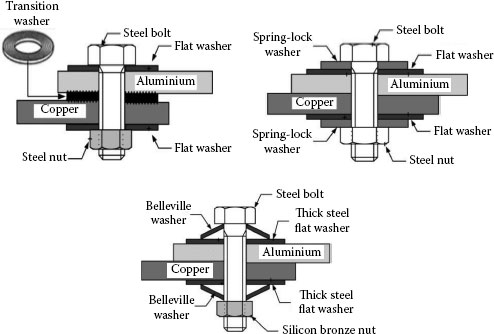
FIGURE 5.78
Recommended bolted joint configurations for aluminum and copper busbar conductors.
TABLE 5.22
Advantages and Disadvantages of Mechanical Connectors
Advantages |
Disadvantages |
|
Inherent resilience of the connector components permits follow-up of creep and reduces the stresses due to thermal expansion that tend to cause excessive creep Ease of installation (sockets, wrenches, screwdrivers, etc) and removal, simple to use, require minimal training to install properly Can be disassembled without damage to the connection components and may be reusable if in good condition Electrical performance of mechanical connectors meets or exceeds the industry requirements for which they are designed, thus, performance is not compromised when using mechanical connectors in tested applications |
Specific torque requirements must be followed to provide the proper clamping force needed for a sound electrical connection Inconsistency of forces applied over identical mechanical installations is not generally repeatable due to use of uncalibrated torque wrenches Because of relatively low mechanical holding strength, these connectors cannot be used as full tension connections and in areas of high vibration; more maintenance and periodic inspection may be required Owing to their geometry, installing mechanical connectors on insulated conductors is usually difficult and awkward |
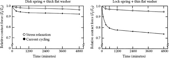
FIGURE 5.79
Effect of mechanical contact devices on the relative contact force in bolted joints.
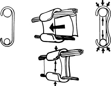
FIGURE 5.80
Schematic of the wedge connector assembling.
The wedge connector incorporates a wedge component and a tapered, C-shaped spring body (or C-body). Installation is made by driving the wedge between two conductors into the C-member deforming it plastically and generating the force that secure the installed wedge and conductors in place. The mechanical properties of the C-member are the most important to the reliable mechanical function of wedge connector. The C-body is characterized by an elastic compliance capable of paying for cable compaction and is therefore responsible for maintaining nearly constant mechanical load on conductors during the lifetime of the connectors. In addition, the relatively small mechanical stresses generated in the electrical contact interfaces prevent significant conductor creep assure the dependable operation of a wedge connector under severe operating and environmental conditions. Figure 5.80 depicts schematically assembling of the wedge connector and the forces generated in the joint. Driving action is produced either by firing a cartridge to propel the wedge at high velocity (powder actuated) or by tightening mechanically driven bolt which drives the wedge between the conductors. As a result, the electrical interfaces are formed by the shearing of rough sliding interfaces in which the large mechanical stresses at the contacting surface asperities generate the conditions favorable to the abrasion and dispersal of oxide and other contaminant films. Metallographic examination of the contact interfaces shows that metal-to-metal contact area is increased greatly [143]. Table 5.23 summarizes the advantages and disadvantages of wedge-connectors.
Mechanical and electrical contact properties of fired wedge-connector have also been investigated by Schindler et al. [143]. It was shown the true operation of fire wedge-connectors are defined by the following factors:
• The relatively low averages mechanical stresses produced at the interfaces with the wedge and C-member within the connector are sufficiently low to preclude significant conductor creep and therefore, minimize loss of clamping force along the conductors.
• The relatively large elastic compliance of the C-body allows the contact forces to remain nearly constant in the face of dimensional changes caused by factors such as temperature variations, conductor compaction etc. The large elastic compliance thus contributes significantly to the connector robustness.
• The abrading action of the wedge causes removal and dispersal of surface oxide films from the conductor and connector surfaces during installation and produces low contact resistances which, in turn, promotes the passage of electrical currents of approximately equal magnitudes through the wedge and C-member, and thus, minimize joule heating and power dissipation inside the connector.
A full tension Class A overhead automatic overhead line splice in accordance with the ANSI C119.4 standard is shown in Figure 5.81. The casing is constructed of high strength aluminum alloy and another aluminum alloy is used for the jaws. The inside of the connector is filled with a factory inhibitor to protect the contact zones from the adverse environmental effects. The intent of this connector assures a very fast installation of aluminum, aluminum alloy and ACSR conductor materials. For easy identification, the end funnel guides are color coded.
TABLE 5.23
Advantages and Disadvantages of Wedge-Connectors
Advantages |
Disadvantages |
|
Powder actuation provides consistent, uniform performance and requires low physical exertion from an operator to complete a connection Rapid mechanical wiping action as the wedge is driven between the conductors breaks down surface oxides and generates superior contact points thus reducing overall contact resistance Installation is accelerated with the use of lightweight, portable tooling with simplified loading and engaging mechanisms The spring effect of the “C” body maintains constant pressure for reliable performance under severe load and climatic conditions whereas a large connector mass provides better heat dissipation Electrical performance of fired-on wedge connectors are excellent due to the low contact resistance developed during installation |
Dedicated nature of powder actuation requires full support from the user in terms of training, maintenance and service To ensure a safe and proper installation, precautions are and specially trained and qualified installers are required for installing wedge connections Mechanical wedge connectors are installed with wrenches, require more physical exertion for installation, and show more inconsistent performance due to discrepancies caused by contaminants on the hardware and wide tolerances of shear-off bolts Mechanical wedge spring bodies are typically manufactured by casting which produces much less spring action to maintain the connection Wedge connectors are restricted to non-tension, outdoor applications and suited only for a limited range of conductors; due to their geometry, full insulation of wedge connector is difficult |
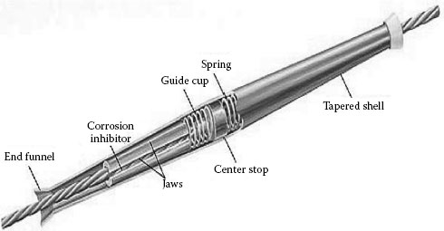
FIGURE 5.81
Automatic overhead line splice. (Courtesy of Hubbell Power Systems.)
This connector has no bolts to slow installation. Installation is simple requiring only locking the jaws of the dead-end open, inserting the conductor between the jaws and tapping the back of the jaws to lock the conductor in place. Once contact between the clamp and conductor is made, the applied spring tension holds the conductor securely thus tightening errors are eliminated; see Figures 5.82 and 5.83. The automatic clamping creates a permanent installation owing to the wedge action which produces the full tension of the conductor. The quality of the installation is not contingent on the workmanship. There’s no feeding of the conductor through the dead-end. Installation of the wedge dead-end is easy because the connector faces the installer. There’s no need for extra tools or special skills and adjustability is easy. The connector configuration resists wind induced motion, galloping, Aeolian vibration and sub-conductor oscillations. The connector construction comprises two standard round conductors twisted around each other at nine foot intervals to change the air foil on the suspension bridge. Full tension dead-end assemblies for ACSR conductors consist of an aluminum deadened body, steel dead-end eye, 15° jumper terminal and terminal mounting hardware. Terminal and tongue have NEMA hole spacing. Figure 5.84 shows this type of connector. The body is made of seamless extruded aluminum alloy tube. The eye is made of galvanized forged steel whereas terminal is made of seamless extruded aluminium alloy tube. Connector terminal hardware is made of ½-13 aluminum alloy.
5.5.8 Shape-Memory Alloy Connector Devices
The shape-memory effect (SME) refers to the ability of certain materials to “remember” a shape, even after severe deformation. When a material with the material body-memory ability is cooled below its transformation temperature (martensite phase), it has a very low yield strength and can be deformed quite easily into a new physical body. When heated above its transformation temperature, it undergoes a change in crystal structure which causes it to return spontaneously to its original shape (austenite phase). During this isotropic transformation process, as the atoms shift back to their original positions, a substantial amount of energy is released. The SMA has high sensitivity to deformation over a narrow temperature range which makes them ideal as disc-spring washers. Furthermore, these alloys have the ability to alter the configuration of the load-deflection curve which can be used to advantage in many applications. Even in improperly installed bolted joints (low contact force), the heat developed by the joint looseness can be used to lower and stabilize the contact resistance in a bolted joint [144,145,146,147]. Table 5.24 shows an overview of identifying SMA products developed and used in different spheres. A detailed review of shape-memory materials is given in CEA Report No. SD-294A entitled “Use of shape-memory materials in distribution power systems” [144]. Comprehensive reviews of general and electrical applications of SMA materials are given in [144,147,148,149,150].
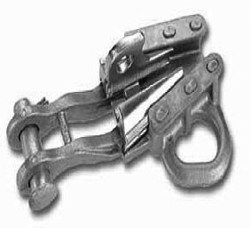
FIGURE 5.82
Fargo GDW 2000 wedge Deadend connector. (Courtesy of Anderson Fargo-Hubbell Power Systems Inc.)
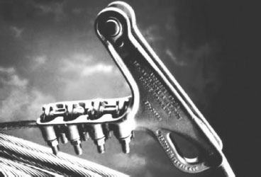
FIGURE 5.83
Anderson SD Deadend Strain Clamp. (Courtesy of Anderson Fargo-Hubbell Power Systems Inc.)
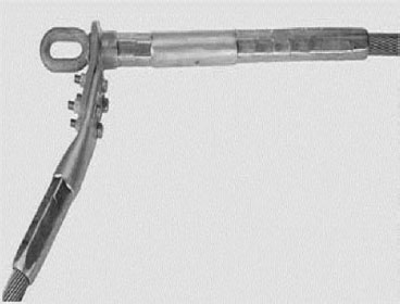
FIGURE 5.84
Full tension deadend assemblies.
TABLE 5.24
Shape-Memory Alloy Applications in Power and Electronics Industries
Electrical Power Industry |
Electronics Industry |
Connectors, circuit breakers, fuses |
Integrated circuit connectors (IC) |
Switches/switching devices |
Zero insertion force connectors (ZIF) |
De-icing/sagging of transmission Lines |
Dual in-line pin connectors (DIP) |
High-power heat engines, robotic devices |
Pin grid array package (PGAP) |
Electrical/thermal actuators, thermo-markers |
Micro-strip connectors |
Overcurrent/overheating protection |
Locking rings for braided terminals |
Optical fibre splices |
Disk drive lift/lower recording heads |
Contact bounce dampers |
|
Nuclear power plant applications |
Shape-memory alloys (SMAs) can be used as disc-spring material. SMAs have a high sensitivity to deformation over a narrow temperature range which makes them ideal as disc-spring washers. The beneficial effect of SMA disc-spring washers is emphasized by the fact that, even with a low initial contact force (faulty installation), the heating caused by the reduced contact force generates an extra strain on the joint, thereby preventing the joint from going bad. Furthermore, these alloys have the ability to alter the configuration of the load-deflection curve which can be used to advantage in many applications. This feature of SMA washer was used by Oberg and Nilsson [147] to demonstrate that even in improperly installed bolted joints (low contact force), the heat developed by the joint looseness can be used to lower and stabilize the contact resistance in a bolted joint. One of the most telling features of shape-memory alloys is that they can be used in many different ways to a broad range of merchandise. These alloys are basically functional devices in that they are more important for what they can do (action) than for what they are (property). Their practical applications are numerous: they have been used successfully as thermal and electrical actuators, thermo-mechanical energy converters, electrical connectors, circuit breakers, and mechanical couplers, as well as in robotic applications, medicine, and other fields. The high sensitivity of shape-memory alloys over a narrow temperature range makes them ideal as a replacement for Belleville washers. Example of the beneficial effect of shape memory alloy mechanical device (washer) in power connection application is depicted in Figure 5.85 depicting the load-deflection dependence of NiTi shape-memory flat washer at 20°C and 65°C [144]. It is clear that as the contact temperature increases the contact force in the joint also increases thus maintaining the joint integrity. Since the material at 20°C is fully martensitic, the load-deflection curve is nonlinear whereas at 65°C it is essentially linear indicating that the material is fully austenitic. This ability of an SMA washer to vary the shape of the load-deflection curve can be used to advantage in many power applications.
The use of SMA washer in power connections is shown in Figure 5.86. Two busbars are joined by a bolt, two flat washers, a nut and two SMA washers interposed between the flat washers (Figure 5.86 Cold state). When the temperature of a joint rises above the SMA transformation temperature, the shape of SMA washers change into a more heat-stable state (austenitic) as they become more curved (Figure 5.86 Elevated temperatures). As a result the contact pressure in a joint increases. The importance of this feature has recently been demonstrated [144]. It was shown that even in improperly installed joints (low contact force), the heat, induced by a loosened joint causes the SMA washer to change its shape and increases the contact pressure. The net result is a stable joint with a low contact resistance.
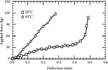
FIGURE 5.85
Load-deflection characteristics of a NiTi shape-memory alloy washer at 20°C and 65°C.
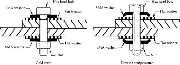
FIGURE 5.86
Effect of SMA flat washer on the joint configuration at low and high temperatures. Note the change in the SMA washer shape at high temperature.
The effect of shape-memory (SMA) and disc-spring (Belleville) washers on the performance of aluminum-to-aluminum bolted joints was under current-cycling conditions has been investigated by Braunovic and Labrecque [145] and Labrecque et al. [146]. It was shown that the use of SMA disc-spring washers produced significant improvement in electrical and mechanical stabilities of bolted joints during current-cycling conditions. The great flexibility and adaptability of SMA technology in a wide variety of electrical applications will eventually make it a part of the electrical industry.
This subject was introduced in Section 5.4.5. The coating of aluminum or copper with different metals is one of the most common commercial practices used to improve the stability and suppress the galvanic corrosion of aluminum-to-copper connectors. The most widely used coating materials are tin, silver, copper, cadmium, and nickel. One of the first comparative studies on the efficiency of coating materials was by Bonwitt who in 1948 [151] investigated the electrical performance of plated and bare bolted aluminum-to-copper connections exposed to elevated temperature and a saline environment. The principal measurement parameter, contact resistance, was measured after the bolted joints were exposed to high temperatures and salt-spray. The coating materials investigated were cadmium, tin and zinc applied to copper busbars. Tin-plated copper followed by bare copper showed the best performance whereas zinc-plated copper was the worst. However, the contact resistance of both tinned and bare copper increased after exposure to high temperature. It was also shown that galvanic corrosion was not eliminated by the coating and that lubrication of bolted busbars was essential in a saline environment. Hubbard et al. [152] evaluated the effect of cadmium, tin, and zinc platings on the performance of aluminum-to-copper joints of different design under current-cycling conditions and in a saline environment. Cadmium on either aluminum or copper and hot-flowed electro-tin on copper were ranked as the most efficient plating materials. Again, lubrication was cited as essential in prolonging the useful life of plated aluminum-to-copper connections in a saline environment. Bond and McGeary [153] evaluated the effectiveness of cadmium, nickel, tin, silver and tin as coating materials in maintaining the stability of aluminum-to-copper bolted-type connections subjected to heat/current cycling conditions and also in a saline environment. It was demonstrated that the nickel-coated connections were superior in performance to another plating material, as evidenced by their stable contact resistance behavior under simulated service conditions. Although widely used in electrical industry, there is mounting evidence indicating that tin neither effectively prevents galvanic corrosion nor ensures the stability of aluminum-to-copper connectors. Tin-plating, traditionally used to curb the adverse effects of galvanic corrosion, requires no special surface preparation prior to assembly and improves the functioning of joints at higher temperatures. There are two main reasons for this:
1. Tin-plated contacts are very susceptible to fretting, which causes severe degradation of contacting interfaces and leads to unacceptably higher contact resistance, instability and, finally, an open circuit.
2. Tin easily forms intermetallic phases with copper even at room temperature, rendering the contact interface very brittle, highly resistant and susceptible to the influence of the surroundings. Lubrication of bolted busbars was essential for reducing the corrosion damage in a saline environment as illustrated in Figure 5.87.
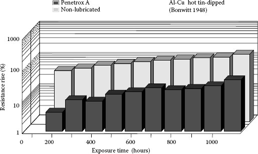
FIGURE 5.87
Effect of saline environment on the contact resistance of lubricated (Penetrox) and non-lubricated aluminum-to-hot-tin dipped copper bolted joints.
Silver plating thickness of 5–15 μm for coating switchgear and enclosed bus is generally considered adequate. Because of the porosity of silver plating, however, a thicker deposit is required where abrasion and weather resistance are factors. Where the joint will be connected and disconnected many times during the life, for instance, of the disconnect switch, the silver plating must be thick enough to prevent exposure of the aluminum or copper through wear. Although silver plating of electric contacts is beneficial in maintaining low electric resistance, it has a potential disadvantage: silver, like copper, is cathodic to aluminum (see Section 2.4.2) and may, therefore, cause galvanic corrosion of aluminum. Furthermore, owing to sensitivity of silver to tarnishing and whisker formation the use of silver-plating in environments where sulfurized contaminants are present has to be avoided; see Chapter 8. The purpose of protective contact aid compounds for optimum performance is essential for silver-coated joints that are exposed to high humidity or moisture.
Most switchgear is installed in relatively clean air with normal humidity. In such cases, lubrication of the silver-plated joints will seal the joints adequately and protect them against the entrance of an electrolyte and the possibility of galvanic corrosion. Some manufacturers use lubrication as a regular practice while others use high temperature wax, such as ceresin wax, dissolved in naphtha, which is easily applied to coat the silver-coated contact surfaces. In outdoor seacoast exposures and in other strongly corrosive atmospheres where galvanic corrosion prevails, inhibitor paints should be used in addition to the contact aid compounds or wax coating. The problem of porosity and excessive wear of silver-plated contacts during make and break operations, as in the type of disconnect switches, can be limited and practically eliminated by welding thin solid silver plates or strips to the copper or aluminum contact blades or jaws [154]. The welded solid silver contact interfaces are impervious to the creep or pore corrosion, less susceptible to fretting, have superior wear resistance and are significantly less affected by the sulfur-bearing environment since, as shown by Kassman-Rudolphi [155] the presence of tarnish films can have a beneficial effect on the contact behavior. Put differently, an appropriate combination of silver and sulfurized film properties can have positive effects on the wear and deformation of the contact and thus outweigh the negative effects of tarnishing on the electrical behavior of contact systems where sliding, fretting and make-and-brake actions are taken.
Nickel-coated connections were superior in performance to another plating material, as evidenced by their stable contact resistance behavior under simulated service conditions. From the available data, nickel appears to be the most practical coating material from the standpoint both of its economy and the significant improvements to the metallurgical and contact properties of aluminum-to-copper connectors. The superiority of nickel to other coating materials was recently confirmed by Jackson [156] who performed current cycling tests on tin-, silver-, and nickel-plated copper busbars bolted to 1350 grade aluminum. The nickel coatings on copper connections showed excellent stability and low initial contact resistance. The poor performance of tin- and silver-plated connections was attributed to the effect of differential thermal expansion between the substrates of aluminum and copper that promotes progressive loss of the contact spots and, thus, deterioration of the contact. Lefebre et al. [157] showed that the instability of aluminum connections can be significantly reduced by a newly developed technology of direct nickel plating. The results of severe current-cycling tests demonstrated excellent stability of the contact resistance of nickel-plated aluminum. However, Aronstein [158] and Hare [159] have demonstrated that although nickel-coated aluminum wire conductors under different operating and environmental conditions had a better connectability than uncoated aluminum wire conductors, the coating/conductor interface was very susceptible to erosion. Braunovic [57] and Bruel and Carballeira [160] on the effect of fretting on the contact properties of nickel-coated aluminum conductors revealed that, despite marked improvement brought about by the nickel coating, fretting still produces a considerable degradation of the contact zones. Lubrication, higher loads and shorter slip amplitudes are found to mitigate these adverse effects.
Braunovic [161] made a comparative evaluation of tin-, silver- and nickel-plated copper-to-aluminum connections on the basis of the performance of coated joints under current-cycling and fretting conditions and ability to protect the contact against corrosion in saline and industrially polluted environments. The results, summarized in Table 5.25, provide an overall assessment of the various coatings. The INDEX was obtained by averaging the absolute values assigned to the performance of joints under different laboratory (current-cycling and fretting) and environmental (saline and industrial pollution) conditions. The lower the INDEX numbers the more efficient the coating material. From this table, it appears that nickel plating significantly enhances the stability of aluminum-to-copper connections (the lowest INDEX), while tin and silver coating show the poorest performance (the highest INDEX) under different operating and environmental conditions.
TABLE 5.25
Summary of Comparative Evaluation of Different Coating Materials for Aluminum-to-Copper Connections
Contact Pairs |
Index |
|
Aluminum (Nickel-plated) |
Copper (Nickel-plated) |
0.7 |
Aluminum (Copper-plated) |
Copper (Bare) |
1.0 |
Aluminum (Bare) |
Copper (Nickel-plated) |
1.3 |
Aluminum (Bare) |
Copper (Silver-plated) |
2.0 |
Aluminum (Bare) |
Copper (Bare) |
2.4 |
Aluminum (Bare) |
Copper (Tin-plated) |
2.7 |
5.5.10 Lubrication—Contact Aid Compounds
It has been known for some time that the use of suitable lubricant (contact aid compound) improves the performance of an electric contact. When the contact is made, the lubricant is forced out from the peaks of high pressure and hence the metallic conduction through the contact is not disturbed (see Section 3.4). As a result, the oxidation of clean metal surfaces is virtually prevented and a high area of metallic contact, hence, low contact resistance, and protection of the contact zone from adverse environmental effects are maintained. Factors affecting lubrication of power connections are shown in Figure 5.88. It is a common practice that for both aluminum and copper busbar connections, the contact surfaces should be abraded through the suitable contact aid compound with a wire brush or abrasive cloth. Due to a more rapid formation of an initial oxide film on aluminum, this procedure is more important for aluminum conductors than for copper. When electrical equipment is furnished with either silver- or tin-plated terminals, the plated contact surfaces should not be rubbed or brushed. Only the contact surfaces of the aluminum or copper bus that are to be bolted to these surfaces should be fixed. It is recommended that such plated surfaces, before being bolted to aluminum or copper bus, be cleaned with cotton waste and then coated with a suitable compound to serve as a sealer only.
Various contact aid compounds have been used for ensuring reliable operation of aluminum and copper connectors. Although many such compounds are commercially available, very little published information relevant to their functioning and efficiency under accepted utility service conditions can be found in the literature. The advantages, properties, functions, and performances of a variety of lubricants for separable and sliding electronic contacts is well documented [162,163,164,165,166]. The contact aid compounds commonly used for aluminum-to-aluminum and aluminum-to-copper connections were evaluated by Braunovic [167] on the basis of their effect on the performance and stability of a bolted joint under current cycling and fretting conditions, contact resistance force relationships, stability to thermal degradation, spreading tendency and ability to protect the contact against corrosion in saline and industrial pollution environment. The results, summarized in Table 5.26 provide an overall assessment of the various compounds and a more quantitative method of comparison. The INDEX is defined as an average of the numerical values assigned to the performance of joints under different laboratory and environmental conditions. The lower the INDEX number, the more efficient is the compound. It was shown that the compounds rendering a low initial contact resistance and having the performance INDEX < 1.0 enhance the stable performance of these connections.
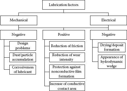
FIGURE 5.88
Factors affecting lubrication of power connections.
TABLE 5.26
Summary of Comparative Evaluation of Different Contact Aid Compounds for Aluminum-to-Aluminum and Aluminum-to-Copper Connections
Aluminum-to-Aluminum |
Aluminum-to-Copper |
|||
Contact-Aid Compound |
Index |
Contact-Aid Compound |
Index |
|
Penetrox A-13 |
0.7 |
Nikkei S-200 |
0.7 |
|
Silicon Vacuum Grease |
0.7 |
Koprshield CP-8 |
1 |
|
Penetrox A |
0.8 |
Penetrox A-13 |
1 |
|
Aluma Shield |
1.2 |
Pefco |
1 |
|
Fargolene GF-138 |
1.2 |
No-Oxid-A |
1.3 |
|
Fargolene GF-158 |
1.2 |
Fargolene GF-158 |
1.4 |
|
Contactal HPG |
1.3 |
Silicone Vacuum Grease |
1.5 |
|
Petroleum Jelly |
1.3 |
Non-lubricated |
1.6 |
|
ZLN 100 |
1.5 |
Contactal HPG |
1.8 |
|
Alcan Jointing Compound |
1.8 |
Petroleum Jelly |
1.9 |
|
AMP Inhibitor |
2.5 |
|||
Kearnalex |
2.5 |
|||
Non-lubricated |
2.6 |
|||
One possible explanation is that the observed difference is connected with the shear strength of the compound film, that is, compounds with higher shear strength will require higher contact forces to bust the compound film on the contacting surfaces and establish metal-to-metal contacts. Hence, it appears that lower shear strength of contact aid compounds is very important in establishing and maintaining a very low joint contact resistance. Another possible explanation is the presence of metallic and/or non-metallic particles added to the compounds to improve their ability to shear the oxide films on the contacting surfaces. Although the results of the analysis of these additives were not sufficient to determine the attributes of such particles, it is most likely that their composition, size, shape, concentration, etc., is most likely responsible for the observed difference. The results are sufficiently consistent to conclude that certain contact aid compounds commonly used for aluminum-to-aluminum connections can also be used for aluminum-to-copper joints. From these results it can be concluded that contact aid compounds with the performance INDEX < 1.0, such as Penetrox A-13 and Nikkei, can be recommended for all connections involving aluminum. It is also important to note that most of the lubricants recommended contain additives in the form of oxide of metallic particles such as illustrated in Figure 5.89.
It was found [131] that the presence of additives in the lubricating oil has significant effects of the connector performance. The connections lubricated with grease An example of the beneficial effect of lubrication (Koprshield) is depicted in Figure 5.90 depicting the variation of the contact resistance of Al–Cu and Cu–Cu wire-plate combinations under fretting conditions. Note the substantial improvement in the contact resistance performance of lubricated wire-plate joints under fretting conditions. In the case of all-copper connections, it is generally accepted practice not to use any contact aid compound. Nevertheless, copper connections are also susceptible to degradation during their service life although their deterioration can proceed for a long time without any appreciable changes in their operation. This is a false sense of security since the experience has shown that the deterioration of copper connections occurs rather abruptly triggered by the accelerated interaction of chemical, thermal, mechanical and electrical processes at the contact interface. Hence, in order to extend the useful service life of copper connections, the use the contact aid compounds such as Nikkei or Koprshield or equivalent having the performance INDEX # 1.0 is strongly recommended.
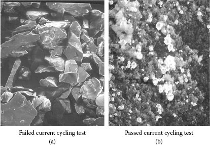
FIGURE 5.89
Scanning Electron Microscopy of particles added to lubricants. The lubricant A with sharp-edged particles failed the current cycling test; whereas the lubricant B with uniformly dispersed spherical particles passed the current cycling test.
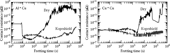
FIGURE 5.90
Effect of lubrication on the contact resistance performance of dry Al–Cu and Cu–Cu wire-plate combinations under fretting conditions.
Another method of circumventing the incompatibility between aluminum and copper is the use of bimetallic aluminum-copper transition contact plates. These bimetallic inserts are copper and aluminium plates joined together by roll-bonding or other jointing methods which insure a continuous interface and good transition bond between those two metals. The bimetallic plates are primarily intended for the busbar type connectors and require the use of contact-aid compound (grease) to prevent the galvanic corrosion at the copper-aluminum interface. Figure 5.91 shows typical configurations for aluminum-to-copper bolted joints when bimetallic inserts are used. To prevent galvanic interaction between aluminum and copper, it is essential to place aluminum busbar and also aluminum side of the bimetallic insert above the copper conductor and also apply the suitable contact aid compound. It should be pointed out, however, that although the bimetallic contact plates reduce the risk of gross corrosion, the problem of jointing aluminum to copper still remains since the two new interfaces aluminum-aluminum and copper-copper, created in the contact zone, may introduce additional impediment to the enactment of the current across the junction. Also, these new contact surfaces have to be processed in the same manner as in the case of aluminum-to-aluminum and copper-to-copper connections that are to be brushed and greased.
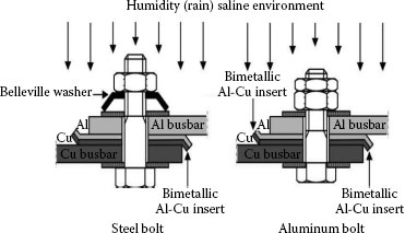
FIGURE 5.91
Typical configuration for aluminum-to-copper bolted joints with bimetallic insert.
An alternative method of joining aluminum-to-copper is the use of a transition washer inserted between the contacting aluminum and copper surfaces. This method of joining is recommended for situations where plating is inconvenient, or where improvements are required for existing installations. The material used for transition washers is either 60/40 brass or high-strength Al–Mg–Si alloy. The sharp surface profile of these washers ruptures the oxide films without the need for further cleaning and establishes a substantially larger contact area that is more resistant to aging than direct surface contact. Examples of these transition washers commonly used in Germany and Great Britain, France, and Canada are shown in Figure 5.92. It is interesting to note that a transition washer made of high strength bronze and having the same geometry is currently used in Germany for jointing copper busbar conductors. It should be pointed out, however, that although these washers do not require surface preparation of the busbar conductors, the use of contact aid compounds is essential. Furthermore, in the case of brass transition washers, there is always a danger of the formation of intermetallics at the contact interface for, if not properly installed, the washer/conductor interface temperature may rise high enough as to elicit the formation of intermetallics.
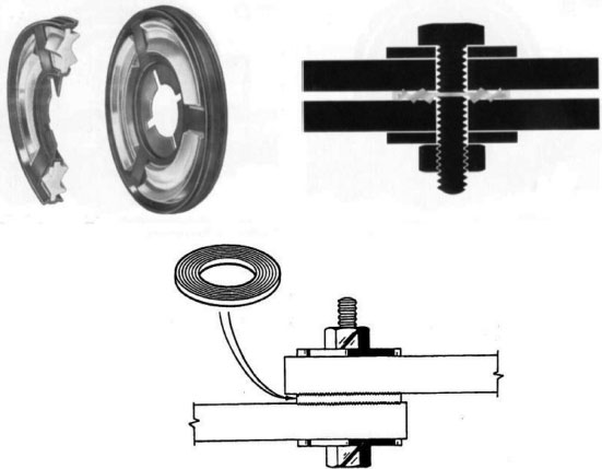
FIGURE 5.92
Transition washers made of Al–Mg–Si alloy (used in Germany) and brass (used in the UK, France and Canada).
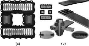
FIGURE 5.93
(a) Multilam contact element, (b) Applications of multilam contacts in busbar connection.
5.5.13 Multilam Contact Elements
The multilam contact elements are another type of transition washers made of copper-beryllium alloys. The basic characteristic of this connector type is a large number of defined lover-type contact points. Each louver form an independent current bridge thus creating a multitude of the current ways that substantially reduce the overall contact resistance. Figure 5.93 shows the application of the multilam contacts in the busbar joints [168]. The advantages of multilam contacts are high-current transmission in hermetically sealed chambers thus eliminating the need for plating, cleaning or lubricating of bus bars, ease of installation, modular design, substantially prolonged service life, cost effectiveness and high operating reliability.
Welding is a highly acceptable method for making connections with all types of aluminum and copper conductors. It creates highly efficient electrical connections which are permanent, economical, have good appearance, and particularly suitable for connecting two members of different cross-section. A properly welded joint is most reliable joint from the electrical standpoint since there is an essentially homogeneous union with no contact resistance to generate heat from high currents. There are a multitude of welding processes that can be used for joining aluminum and copper but only those most commonly used for welding power connections and conductors will be drawn. A detailed description of different welding processes can be found in ASM Handbook Volume 6 “Welding, Brazing and Soldering” [169].
5.5.14.1 Thermite (Exothermic) Welding
Thermite welding is a fusion welding process in which two metals become bonded over being heated by superheated metal that undergoes an aluminotermic reaction. The liquid metal resulting from the reaction between a metal oxide and aluminum acts as the filler metal and hangs around the conductors thus making a molecular weld. Thermite welding is extensively used for making grounding connections between copper conductors. The advantages of this process are excellent current-carrying capacity equal to or greater than that of the conductor, high stability during repeated short-circuit current pulses and excellent corrosion resistance and mechanical strength. Advantages and disadvantages of exothermic (termite) connections are presented in Table. 5.27. Figure 5.94 show typical crucible-mold setup for welding copper conductors.
Friction welding is a solid-state welding process in which the passion for welding is produced by direct conversion of mechanical energy to thermal energy at the contact interface without the application of external electrical energy or heat from other sources. Friction welds are created by taking a non-rotating work piece in a contact with a rotating work piece under constant or gradually increasing pressure until the interface reaches welding temperature and then the rotation is interrupted to complete the weld. The frictional heat produced at the interface rapidly raises the temperature of the work pieces, over a very short axial distance, values approaching but bellow the melting range. During the final stage of welding process, atomic diffusion occurs while the interfaces are in contact, allowing a metallurgical bond to form between the two fabrics. This welding process is used to make bimetallic aluminum-to-copper terminals and thus avoid direct contact between aluminum and copper. These terminals are usually copper flat plates or tubes friction welded to compression-type aluminum connectors. When installed, the friction welded terminals convert the aluminum-to-copper joint into an aluminum-aluminum and copper–copper joint. This type of a connector is widely used in Europe. Figure 5.95 illustrates a typical friction welded terminal.
TABLE 5.27
Advantages and Disadvantages of Exothermic (Thermite) Connections
Advantages |
Disadvantages |
Excellent current-carrying capacity equal to or greater than that of the conductors, high stability during repeated short-circuit current pulses, excellent corrosion resistance and mechanical strength |
Cost, lack of repeatability, numerous mold requirements, potential down-time caused by inclement weather or wet conditions, safety risks to personnel and equipment |
The intense heat damages both the conductor and its insulation, anneals the conductor so that exothermic connections cannot be used in tension applications |
|
The resultant weld material exhibits lower conductivity and physical properties than the conductor, being similar to cast copper |
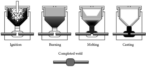
FIGURE 5.94
Typical crucible-mould set-up for thermite welding of copper conductors.
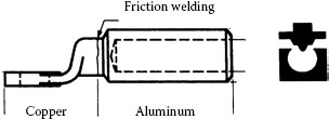
FIGURE 5.95
Typical friction-welded terminals.
Explosive welding is a cold weld pressure welding in which the controlled energy of a detonating explosive is used to create a metallurgical bond between two or more similar or dissimilar metals. No intermediate filler metal, that is, brazing compound or soldering alloy is needed to promote bonding, and no external heat need be given. Diffusion does not occur during bonding. As a consequence of the high-velocity collision of the two metals, the contaminant surface films are jetting off the base metals. The best attribute of the explosive welding is that dissimilar metal systems can be bonded even when conventional fusion welding techniques are metallurgically unacceptable because of the formation of intermetallic compounds. The most common use of explosive welding is the production of corrosion resistance clad metals and transition joints used to aid dissimilar metal welding. This technique has been used for splicing the overhead transmission lines [170]. The explosively welded connectors are completely metallic, void free and offer a totally compressed uniformly smooth and straight fitting without bird caging the conductor. The explosively welded connectors are completely metallic, void free, and offer a totally compressed uniformly smooth and straight fitting without bird caging the conductor. However, despite the apparent advantages of this technique for splicing the transmission lines, there is a number serious disadvantage such as the safety of the personnel during installation and considerable noise which limits the use of this technique in highly remote geographic locations. During the explosive welding of high residual stresses are brought forth in the bond zone that can significantly increase the creep and stress relaxation of a joint, hence, annealing is required to remove these stresses. Furthermore, because of the high pressures generated in the bond zone will exceed the dynamic yield stress of the metals and they will flow plastically during the procedure.
Resistance welding is a procedure in which varying surface are joined in one or more spots by the heat generated by resistance to the flow of electrical current through busbars or conductors that are held together under force by electrodes. The contacting surfaces in the area of current concentration are heated by a short-time pulse of low-voltage, high-amperage current to form a fused nugget of weld metal. When the flow of current ceases, the electrode force is preserved while the weld metal rapidly cools and solidifies. This method of welding is widely used for joining copper and copper alloys. The resistance weldability of any copper alloy is inversely proportional to its electrical and thermal conductivities. Most copper alloys require a short weld time, low electrode force, and high current and different electrode materials that are compatible with the alloy being welded.
Resistance brazing is essentially a resistance welding process in which the work pieces are heated locally and filler metal, inserted between the work pieces, melts by the heat obtained from the resistance to the flow of electric current through the joint. Parts of any shapes can be resistance brazed, provided the surfaces to be joined are either flat or conform over a sufficient contact area in order to maintain the pressure permitting the heating current to flow through the joint, thus, enabling the filler metal to be distributed throughout the joint by capillary action. This welding process is very suitable for joining copper and its alloys. The use of high-resistitivity electrodes provides an efficient method of localized heating at the joint but the avoiding fusion of the copper base metal. A flux is used in almost all resistance brazing since it provides a coating that prevents or minimizes oxidation of the joint during heating, dissolves oxides present or formed during heating and assists molten filler metal in wetting the contact zone to promote capillary flow. Somewhat a similar resistance brazing method has been recently developed by Nguyen-Duy et al. [171] to join solid silver plates to copper for the contacting members (jaws and blades) of high-voltage disconnect switches. Instead of traditional filler metals, the amorphous silver was used. The effects of severe wear, current-cycling and short-circuit tests, conducted on the switches having solid silver contacts, showed significant superior performance when compared with those having silver coated contact surfaces.
In order to match the mechanical and electrical requirements and also assure reliable performance of a connector during its expected service life, various plans have been developed and used in the field with varying degree of success. The generic connector designs commonly used on distribution network are illustrated in Figure 5.1. The field experience has shown that a wide variety of connector designs have given good service over several years, but the factors contributing to their success and to failure elsewhere could not be ascertained with any degree of certainty. However, the ever-increasing demand for electricity in recent years increased electrical loading on power transmission and distribution lines by many utilities which, in turn, raised the average operating temperature of conductor lines, up to 130°C during times of peak force transmission. Connectors are now required to run reliably at relativistic elevated temperatures.
The field and laboratory tests showed that most of the compression-type connectors and non-lubricated aluminum-to-copper or aluminum-to-tin plated copper busbar joints showed the greatest instability, whereas the fire-driven wedge and bolted type with adequate surface preparation and lubrication showed the most stable contact performance under different operating (environmental) and current-cycling conditions. Typical effects of current-cycling and field exposure tests are presented in Figures 5.96 and 5.97. The result of 10 months exposure in saline and industrial environments on the performance of lubricated and non lubricated bolts-type connectors are shown in Figure 5.98. The contact configurations Al–Ni, Al–Ag, and Al–Sn are Al-base conductors in contact with Ni-, Ag-, and Sn-plated copper-conductors. The superior performance of nickel-plated connections is evident. Detailed surface analysis of the connectors exposed to a saline environment indicated that severe corrosion had occurred and that corrosion products accumulated between the connector aluminum body and copper conductor. Accumulation of these products was most pronounced in compression-type connectors. The severity and tenacity of the saline environment could not prevented by using the water-sealing products (mastic, tapes) since the severe corrosion and accumulation of corrosion products were clearly evident in the connectors completely covered by this supposedly water-sealing mastics or tapes. Covering the connectors with the products that cannot insure a complete hermetic seal would result merely in an accelerated corrosion since the water-sealing agents will prevent the escape of corrosion products from the contact zone.
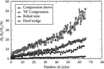
FIGURE 5.96
Effect of current-cycling on the contact resistance of different types of connectors. (Ri is the maximum contact resistance after the i-th cycle; R0 is the initial contact resistance at zero cycle).
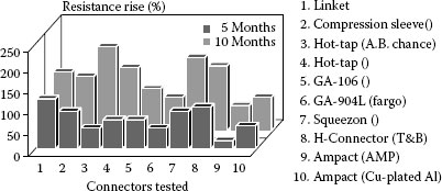
FIGURE 5.97
Effect of field exposure in a saline environment on the contact resistance of different connectors.
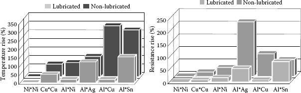
FIGURE 5.98
Effect of 10 months of exposure to saline and industrial environments on the performance of lubricated and non-lubricated bolted-type connections. Note: Al–Ni, Al–Ag, and Al–Sn are Al–base conductors in contact with Ni-, Ag-, and Sn-plated copper-conductors [172].
5.5.15.1 Fired Wedge-Connectors
Jondhal et al. [173] and Sprecher et al. [174] evaluated a number of different tap-connectors commonly used on the web to provide an electrical connector between a main power cable and a tap conductor. The evaluation was prompted by the results of infrared surveys of the overhead facilities indicating that a substantial number of the tap-connectors were running unacceptably hot. The evaluation was implemented in accordance with the accepted testing procedure as specified by the ANSI C119.4 standard. The results showed that fired wedge-connectors perform best overall in all the tests carried out. Fired wedge-connector technology appears to be superior to all other joining technologies. Although compression “H” connectors performed well with service-aged/cleaned conductor, they did not pass the more severe test using the as-received/uncleaned service-aged conductor. Similarly, the compression sleeve connectors performed well with the as-received/uncleaned service-aged conductor but, surprisingly, performed less well with cleaned serviced-aged conductor. It is concluded that neither compression “H” nor compression sleeve connector technology ranks as highly as wedge-connector technology. It should be pointed out that despite the seeming advantages of firing wedge-connectors, their role is limited to overhead line applications and are unsuitable for the role of the underground systems. The most common types of connectors used for the underground systems are hexagonal or stepped deep indentation compression-type connectors.
5.5.15.2 Stepped Deep Indentation Connectors
Stepped deep indentation connectors use a specially-designed crimping technique to attach a conductor permanently to the connector. The crimp, made on one side of the barrel carrying the conductor, is carried out using a cylindrical or oblong punch with two cone steps and a die that fully encloses the connector. Full enclosure of the connector is necessary to control the deformation of both the connector and conductor. The small inner indentation maximizes compaction of the conductor strands to decrease interstrand electrical resistance. Generally, two separate two-stepped indentations are made along a line parallel to the axis of the connector bore to enhance strand compaction. Owing to the deformation of the connector and conductor, all the metal displaced by the punch is subjected to compressive and shearing forces that generate significant cold welding between the deformed connector walls and the displaced conductor strands. This increases the shear strength of the connector/conductor interface and thus increases the mechanical holding force on the conductor. One of the main features of stepped deep indentation connectors is that all the conductor strands participate in current conduction, thus yielding exceptionally low contact resistance. Since the walls of the small deep indentation can only be deformed in compression, the two cone steps generate a deformation geometry that resists the metal flow in the connector after crimping. Thus the electrical interfaces do not degrade owing to creep flow or stress relaxation in the connector.
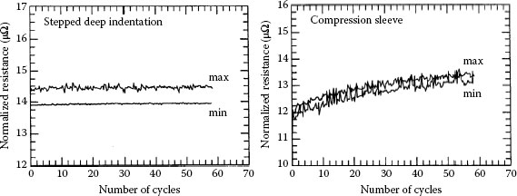
FIGURE 5.99
Effect of current-cycling on the normalized contact resistance of 500 kcmil stepped deep indentation and compression sleeve connectors.
The reliability of different types of connectors commonly used for the underground network has been evaluated by Braunovic [175]. The connectors evaluated included compression sleeve, bolted, elbow (load break) and steeped deep indentation connectors. The effects of accelerated current-cycling tests showed that steeped deep indentation and bolted (with proper surface preparation and lubrication) connectors showed superior performance over that of the compression sleeve and elbow connectors. The results of current-cycling tests for stepped deep indentation and compression sleeve connectors are shown in Figure 5.99. It is clear that the contact resistance of stepped deep indentation connector was not affected by the current-cycling while the compression sleeve connector showed unstable behavior as manifested by a gradual increase of its contact resistance with the number of current cycles. The inferior performance of the compression sleeve connector is attributed to its pattern which does not provide sufficient mechanical deformation to bring down the initial contact resistance to a level where it is independent of the deformation applied. Actually, the initial contact resistance of compression sleeve connector was about 30% higher than that of the stepped deep indentation connector. It seems that in the compression connector the contact surface does not fully envelope the conductor which leads to a greater tendency to substantial relaxation from the slippage of strands subsequent to installation.
Electrical connections are designed to operate over a long period of time. However, their age and their life span and optimum life cycle managements are affected by a number of factors, such as original design criteria, manufacturing process, operating conditions, maintenance procedure and safety consideration. Hence, the accumulated damage can be measured, their history analyzed and an expected remaining life calculated. The remaining life is the period of time after which the probability of failure becomes unacceptably high. A common feature in usefulness and life expectancy of any component is expresses by the well-known “bathtub” reliability curve, shown in Figure 5.100. As can be seen, there is a high probability of failure during the first few hours or weeks of operation, break-in (start-up) period, usually caused by manufacturing or installation problems. Following this initial period, the probability of failure is relatively low for an extended period (normal life) until it increases sharply with elapsed time or hours of operation (wear-out period). The sum of operating time and the most probable expected remaining life may or may not match the original design life. Hence, the expected remaining life, while still a range or a probability distribution, will probably be more precise. Every component of an electrical system can reach the failure situation, which will likely occur as the operating time approaches the end of its life span. The useful lifetime of an electrical component or a device is determined by the design and manufacture and is affected by a series of service conditions considered as normal. Clearly, if during the lifespan of a component the operating conditions are or become more severe than expected, the useful life will be shortened at a higher rate.
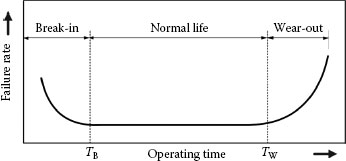
FIGURE 5.100
Failure probability (“bathtub”) curve.
5.6.1 Economical Consequences of Contact Deterioration
Electrical connections are designed conservatively. The properties of the materials used in the connections may deteriorate owing to in-service aging or under the influence of deterioration mechanisms that can reduce their useful lifespan and/or reduce their operating safety margin. Stretching out the use of older connections beyond their originally anticipated life can offer major economic benefits. In order to draw out their operating life, however, their remaining useful lifetime must be evaluated to ensure that safety and structural integrity are held during the extended operating period. Managing and extending the life of critical power equipment require reliable and continuous monitoring as the validity of any action taken regarding the lifetime of a component. Once an error has been discovered and its evolution is monitored, the severity of the defect can be assessed and decisions made what actions to be considered [176]. Potential damages will be restricted when incipient faults are detected and timely actions implemented. Early detection limits the amount of adjacent damages and confines the area calling for repair and maintenance. The early detection of incipient faults will greatly reduce unplanned power outages and improve the reliability of the power and service supplied. Furthermore, since fault conditions often lead to catastrophic failures, their early detection will limit these consequences and thus insure the safety of the substation personnel. Monitoring a fast developing fault and evaluating its progress provides the necessary information to apply all the substantive resources to react on time and reduce the overall damages. Itemized power equipment/components susceptible to ageing and different modes of deterioration, identify the cause and indicates potential impact and cost are shown in Table 5.28.
In recent years, power quality has become an important issue and is receiving increasing attention by utility companies, equipment manufacturers and the end-users. Power quality is defined as the interaction of electrical power with electrical equipment. Correct and reliable operation of electrical equipment without being damaged or stressed qualifies as good electrical power quality. If the electrical equipment malfunctions, is unreliable, or is damaged during normal usage, the power quality is poor. Generally speaking, any deviation from the normal circuit voltage source (either DC or AC) can be classified as a power quality. Most power quality problems are chain reactions. An incipient event causes an electrical disturbance, which is conducted by electrical system and eventually reaching all electrical equipment from power connectors to sensitive electronics. The most common power quality issues shown in Figure 5.101 are as follows:
TABLE 5.28
Itemized Power Equipment/Components Susceptible to Ageing
Application |
Cause |
Impact |
|
Power distribution Circuit breakers Conductors Splices Disconnect switches Miscellaneous power components Switches breakers |
Poor breaker connections Overheating, overloading Conductor strands broken Loose/corroded/improper connections and splices Loose/corroded connections Poor contacts Overloading Overheating |
Overheating, arcing, burning, fire Conductor strands broken—overhead line could come down Expensive repair and replacement Safety considerations Arcing, short-circuiting, burning, fire 25% of all power equipment failures are caused by loose electrical connections Cost of repair and replacement very expensive Safety considerations |
|
Transformers |
Loose/deteriorated connections Overheated bushings Poor contacts (tap changer) Overloading |
Arcing, short-circuiting, burning, fires Expensive rewinding and replacement |
Note: Different modes of deterioration identifies the cause, potential impact, and cost.
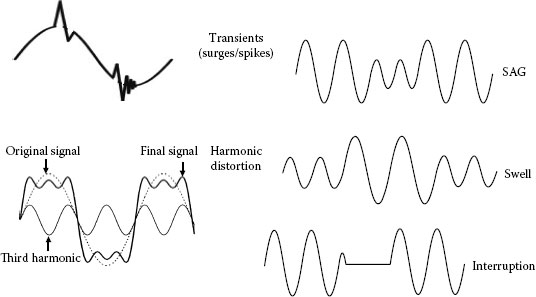
FIGURE 5.101
Most common electrical disturbances found in the electrical system.
Disturbances refer to power quality variations that occur at random intervals but are not associated with the steady-state characteristics of the voltage.
Transients, also called surges and spikes, are distortions of electricity caused by lightning, large motors starting, routine utility activities and other conveniences.
Harmonic distortion is deviation from a perfect sine wave represented by sinusoidal components having a frequency that is an integral multiple of the fundamental frequency caused by the power supplies of certain electronic appliances, including televisions, fax machines, and especially personal computers. Harmonic distortion can overheat building transformers, building wiring, wiring in modular office panels, motors, and components in some appliances. This results in an increase in power consumption. The immediate effects of harmonic distortion are an increases in peak voltage, malfunctioning of control and/or regulation circuits, false switching of electro-technical and electronic equipment and interfere with the neighboring telecommunication lines.
Sag is a short (less than a second) decrease in the normal voltage level caused by faults on distribution and transmission circuits. Sags do not damage equipment, but can cause computers to restart or lock up and other appliances to lose memory. Even though the effects of these disturbances can be the same as long-duration outages, voltage sags can be more important because they occur much more frequently.
Swell is a short (less than a second) increase in the normal voltage level. Mostly caused by motors stopping, swells generally do not upset or damage appliances but can initiate the failure of a stressed component in an electronic appliance.
Interruption is defined as a momentary power outage that can last anywhere from fractions of a second to hours. Caused by lightning, downed power lines, tripped circuit breakers and blown fuses, interruptions disrupt computer processes, clocks and the memories of unprotected electronic devices.
It is important to note that many power quality characteristics are a function of both the supply system and end-user system and equipment characteristics. A sound understanding of electrical power quality and its impact on the operation of power systems is a vital part of acquiring the best blueprint for equipment specifications and for facility protection. In general, equipment should be designed to withstand the normal steady-state power quality variations expected as part of the normal operation of the power system. An essential prerequisite for maintaining the structural integrity and retaining the reliability of power connectors throughout their service life is to control within defined limits their potential aged-related degradation. This can be accomplished through a systematic age-related degradation management process consisting of the following tasks:
• Understanding deterioration mechanisms—Failure modes
• Minimizing degradation of power connectors
• Inspection, monitoring and assessment
• Maintenance, repair and replacement
• Development of utility centered maintenance program
Although much progress has already been made in diagnostic and monitoring of functioning and efficiency of power
The most important prognostic model requirement is the estimation of the remaining life of individual components such as connectors and disconnects switches, rather than that of a population of components. Accurate prognostication enables different palliative measures to be developed and trained towards power equipment most susceptible to deterioration owing to ageing, environmental and other adverse influences affecting its performance and properties. One of the most important prerequisites for developing prognostic model is a collection of information on the performance of a powerful component of its initiation through final state. Development of a prognostic model comprises two important but separate parts: model derivation and validation. Deriving and validating a model along the same dataset leads, by definition, to over optimistic estimates of the model’s accuracy. A statistically valid model provides unbiased predictions when applied to new datasets, but this quality does not necessarily mean that the model has applicable validity. To be applicable the model must be precise enough to serve the purpose for which it was acquired. Models based only on genes which are highly related to the component performance are more likely to be similarly predictive in some other context. From a practical viewpoint simple models are more likely to be readily integrated into utility maintenance and predictive practices with minimal disruption.
5.7.1 Prognostic Model 1 for Contact Remaining Life
For the prognostic model of remaining life of power connection it was assumed that the contact interface is homogeneous with a ring shaped a-spot as shown in Figure 5.102 [177]. For the purpose of this example, it was assumed that ingress of oxygen and oxide film growth is one of the key factors affecting the conductive area in contact between two metallic surfaces. A full description of this model can be found in Reference [2]. Figure 5.103 shows the calculated contact lifetime of a bolted connection as compared with the observed contact resistance variation with time.
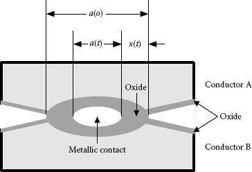
FIGURE 5.102
Schematic view of the contact spot.
5.7.2 Prognostic Model 2 for Contact Remaining Life
The contact ageing process is schematically illustrated in Figure 5.104. Stage 1 is a running-in period, stage 2 is a normal operation period and stage 3 is the intensive ageing period. One of the essential tasks of reliability theory is the prediction of the residual lifetime of an article at the melting stage. According to theoretical approach to reliability, the proper methods for forecasting residual life are based on the physical statistical evaluations. These methods are based both on the statistical mathematical methods (time series analysis) and the physical modeling of the object ageing. It should be mentioned that a time dependence of a contact resistance R(t) is not a smooth function. It is a sum of a regular component (trend) and stochastic fluctuations that are shown in insert in Figure 5.105. From the statistical point of view the contact resistance time dependence R(t) is a typical example of a non-stationary stochastic process [178].
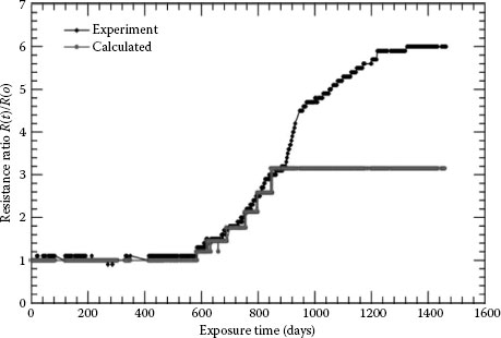
FIGURE 5.103
Example of predicting the remaining life of bolted connection.
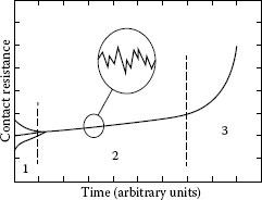
FIGURE 5.104
Schematic of the ageing process of a permanent electrical contact.
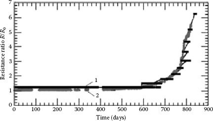
FIGURE 5.105
Estimated and experimentally observed contact resistance of a bolted joint (1) Estimated; (2) Experimentally observed.
Takano and Mano [179] were the first to propose a diffusion model of ageing of an electrical connection; see Figure 5.106. According to this model, the insulation surface film grows into the contact interface as a result of diffusion of an oxidizing agent within the contact area. In the central zone of a contact spot there is a quasimetallic area, where the surface film is negligibly thin. The conductivity of this quasimetallic area is rather high owing to tunnel and thermo-ionic mechanisms of current transfer. As the film thickness increases the radius of quasimetallic spot decreases.
Shape-memory alloys were introduced in Section 5.5.8. Although they were observed as long ago as 1938, they were not widely recognized until 1962 when the Ni-Ti alloy was discovered by Buehler et al. [180] of the U.S. Naval Ordnances Laboratory. The alloy was named “Nitinol” for (NI)ckel-(TI)tanium Naval Ordnance Laboratory (NOL). The SME is unique to two groups of alloys: nickel-titanium (Ni-Ti) and copper-based alloys (Cu–Zn–Al and Cu–Ni–Al) whose transition temperature is highly sensitive to the alloy composition and thermo-mechanical treatment. In the case of Ni-Ti, the temperature can be varied from −200°C to +100°C, whereas with copper-based alloys it can range from −105°C to +200°C. Their practical applications are numerous. Comprehensive reviews of the general applications of shape-memory materials and in the electrical industry are given by Schetky [149] and Braunovic [150].
5.8.1 Origin of Shape-Memory Effect
The shape-memory effect is a consequence of the continuous appearance and disappearance of martensite with rising and falling temperature [180]. The martensitic transformation is spontaneous and reversible, and occurs during cooling from the parent phase or austenite to the martensitic state or martensite. This phase transformation is a first-order displacive transformation in which a body-centre cubic phase (austenite), on cooling, transforms by a shear-like mechanism to martensite, which is both ordered and twinned. The martensitic transformation is diffusionless, that is, it involves a cooperative rearrangement of atoms over a short distance into a new stable crystal structure without changing the chemical nature of the matrix; see Figure 5.107.
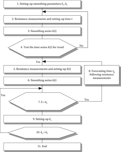
FIGURE 5.106
Residual life flow chart for electrical contacts.
The one-way memory effect can be explained simply, using two examples: a straight SMA wire fixed at one end and a bent wire (Figure 5.108). Stretching or bending the wire beyond its yield point at room temperature results in deformation after unloading and the wire will remain in the stretched or bent condition until it is heated to above the transformation temperature of the alloy (Af) no load is applied, it will return to its original shape. Subsequent cooling below the transformation temperature (Mf) causes no macroscopic shape changes. The one-way effect can be repeated many times. Reactivation of the shape-memory effect can only be done by deforming the wire in the martensitic state. Since no special treatment is necessary, cyclic use of the oneway memory effect with external reset force in many instances is the more economical solution.
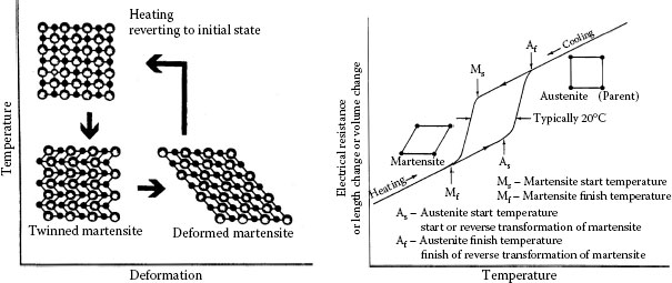
FIGURE 5.107
Schematic of one-way and two-way shape-memory effect.
The two-way memory effect refers to the ability of SMA to assume one shape in the martensitic state (low temperature) and then spontaneously change to a second shape when heated to above Af (high temperature) (Figure 5.107). This process can be cycled fairly reproducibly between different shapes by simply changing neither the temperature, providing the strain level involved is not excessive nor the exposure temperature too high. The two-way effect can only be produced by special thermomechanical treatment (“training”) which comprises multiple heating/cooling cycles under the same applied external force, thus allowing the material to “remember” the training process.
5.8.2 Applications of SMA in Power Connections
The SMA technology has not yet penetrated the electrical industry significantly, in part owing to a general lack of awareness as well as to the rather limited engineering data available about shape-memory materials. However, a growing use of such materials indicates a wider recognition of the advantages and potential of this technology.
The first SMA connector, called Cryocon [181] was a pin-and-socket type developed by Raychem Corporation in the mid 1970s for the Trident Missile Program. The connector forms a high-compression fit yet can be quickly released and recoupled. The design is in the form of a heavy walled tube referred to as a biasing spring (typically of made of Be-Cu alloy or other conductive spring material) and a ring made of Ni-Ti, called the driver; see Figure 5.108.
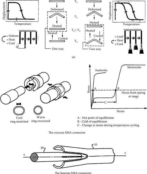
FIGURE 5.108
Crycon pin-and-socket connector with its stress-strain characteristics and the Souriau pin-and-socket connector.
The Souriau connector [182] is a pin-and-socket type and operates using the two-way memory effect. After training, the SMA (Cu-Zn-Al) socket can function in two states: open when cold and closed when hot (ambient temperature). The make/break operations can be performed many times without destroying the electrical continuity or mechanical strength of the connector. The gripping forces developed in the Souriau connector are five times higher than those exerted in a conventional connector thus providing good resistance to shock and vibration. A simplified schematic of the Souriau connector is also seen in Figure 5.108.
In recent years a number of very simple SMA-based temperature indicators have been developed and used on the network. The advantage of this type of temperature indicator over infrared (thermography) detection is the possibility of continuous supervision of the condition of the joints, electrical contacts of different units of power system equipment and devices, etc. Furthermore, owing to intrinsic characteristics of the shape-memory materials, these indicators can be used as activators which can collect and transmit the collected temperature data to a remote computer-based data acquisition system, located usually, but not necessarily, at substation. These activators can also provide on-site monitoring of the equipment performance and interpretation of this data in terms of Pass/Fail warning and event marking such as date, duration and number of temperature excursions and, thus, a more detailed assessment of the state of various devices and contact junctions on the power system [183,184]; see also Reference [2].
In recent years there has been considerable increase in interest for metal foams Such an unabated interest in these materials is a result of not of only what these materials are but more so what they can offer in terms of a variety of properties [185,186,187,188,189]. Metals foams are a new class of materials with low densities and novel physical, mechanical, electrical, thermal and acoustic properties. Owing to their intrinsic structure and attributes, the metallic foams offer significant performance gains as the efficient energy absorbers for light, stiff structures, efficient absorption of energy, sound and vibration, and other unique and specialized applications.
The most widely used and investigated metallic foams are aluminum- and aluminum alloy-based foams. Aluminums foams have very interesting properties, in that they preserve many of the general characteristics of the parent metal, while offering the very high strength to weight ratios of honeycomb type structures and enhanced abilities for energy and sound absorption, as well as enhanced impact, insulating and shielding characteristics. Figure 5.109 illustrates some typical aluminum foam-based materials. The foam material is enclosed between solid aluminum plates. It can be closed cell or open cell: see Figure 5.109a and b. Mechanical properties of aluminum foams are best illustrated by their stress-strain characteristics as shown schematically in Figure 5.110. The enhanced properties of aluminum foams generate new substitution opportunities for aluminum, steel, wood sheathing, other composites and materials in market applications where their characteristics ensure new added values:
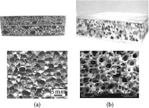
FIGURE 5.109
(a) Typical foam materials (b) Foam material is enclosed between solid aluminum plates. (Courtesy of A.G.S. Taron Technologies.) and examples of (a) Closed cell and (b) Open cell aluminum foams.
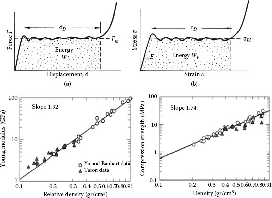
FIGURE 5.110
Schematic of compression stress-strain characteristics of aluminum foam [188] and Young modulus and compression strength as a function of foam relative density and density, respectively.
• Ultra light weight of aluminum foams results in a factor of 5 in terms of reduction in weight compared to steel of equal stiffness.
• Energy and vibration absorption properties of aluminum foams allow absorption of a large quantity of mechanical energy at almost constant pressures and thus open up significant potential in armouring applications for commercial, industrial and military uses.
TABLE 5.29
Mechanical Properties of Foam Materials Produced by Different Manufacturers of Aluminum Foam Materials
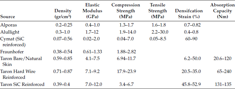
• Mechanical damping capacity of metallic foams is omni-directional and larger than that of solid metals by up to a factor of 10; see Table 5.29.
• Thermal management characteristics of metallic foams provide exceptional heat transfer ability and resistance to direct flame and combustion reduce system costs when used as wall structure in thermally controlled containers or rooms.
• Acoustic absorption capacity of metallic foams is owing to their reticulated structure.
5.9.1.1 Electrical and Thermal Properties of Foam Materials
Figure 5.111 depicts the variation of electrical conductivity of a number of aluminum foam materials as a function of relative density [188]. The resistance data were obtained by placing the micrometer probes inside the foam and measuring the resistance sampled by the potential probes. From the data shown, it appears that the conductivity data can be approximated by the following expression:
(5.34) |
Where α is a coefficient α = 0.05. This expression is shown as a continuous line on Figure 5.111a. Figure 5.111b shows the thermal conductivities of aluminum foam and dense aluminum foam precursor. As it can be seen thermal conductivity of aluminum foams is several orders of magnitude lower than that of precursor. Therefore, owing to such low thermal conductivity, aluminum foams are generally not suited for simple thermal insulation but can be used for fire protection.
5.9.1.2 Power Connection Applications
The mechanical and physical properties of metal foams are determined by their cellular structure and relative density that are strongly dependent on the production method and the production parameters; see Table 5.30. It should be borne in mind, that although the specific mechanical and physical properties of cellular metals are inferior to their bulk properties, the metallic foams can, nevertheless, be efficient when their structural properties are explicitly used. The current transfer across the contact with aluminum foam washer is shown schematically in Figure 5.112 [190].
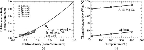
FIGURE 5.111
(a) Relative electrical conductivity of aluminum foams as a function of relative density, (b) Thermal conductivity of aluminum foam and aluminum precursor.
TABLE 5.30
Properties of Metallic Foam Materials
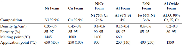
Notes: Density depends on production technology, composition and porosity. Temperature applications depend on production technology, composition and aggressive environment.
The pore size of copper foam materials ranges from 0.1 to 10 mm. The porosity is in the range of 50–98%. The volume density is in the range 0.1–0.8 g/cm3. Metallic foams typically retain some physical properties of their base material. Foam made from non-flammable metal will remain non-flammable and the foam is generally recyclable back to its base material. Coefficient of thermal expansion will also remain similar while thermal conductivity will likely be reduced. Figure 5.113 illustrates some shapes of copper foam materials.
5.9.2.1 Applications of Copper Foam Materials
The performance of copper-based connections can be greatly improved with the use of Ecocontact [191] inserts made of copper-based foam materials; see Figure 5.114. The foam enhances contact between contacting members and eliminates electric overload. It ameliorates the current transfer across the contact interface of a used or damaged connection with no surface renovation beforehand. Installing Ecocontact foam does not require any specific operation. Properties of different types of metallic foam materials are shown in Table 5.30. The performance of bolted joints with the use of Ecocontact copper-based joints under normal loading conditions with the use of foam insert is shown in Table 5.31. As it can be seen the use of Ecocontact inserts considerably improves the performance of bolted joints as manifested by a substantially lower operating temperatures and power losses as compared with those without these inserts.
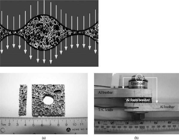
FIGURE 5.112
Schematic of current transfer across the contact with aluminum foam washer and (a) Aluminium foam,
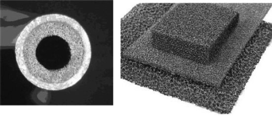
FIGURE 5.113
Shapes of copper foam materials.
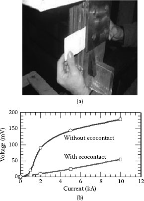
FIGURE 5.114
(a) Installation of Ecocontact copper-based foam insert; (b) Voltage-current dependence of connections with and without the use of Ecocontact.
TABLE 5.31
Effect of Ecocontact on the Performance of Copper-Based Bolted Joints
Temperature |
ΔU |
Power Loss |
|
Without ecocontact |
>250°C |
350 mV |
3500 W |
With ecocontact |
40°C |
3 mV |
30 W |
After 1 month of operation |
40°C |
2 mV |
20 W |
The contact foams are produced by evaporation of pure silver in a vacuum. These foams, with their honeycomb structure, offer good porosity and malleability characteristics. The honeycomb structure enables production of surface comprising thousands of micron-sized contact points (up to 130, 000 points/in.2 for a foam thickness of 0.08 in. [20 cm]). These micro-points perforate the oxide layers, thus creating micro-welds and eliminating any current concentration in the contact zones. The Ecocontact silver foams allow to increase the service life of high-amperage connections by slowing down contact surface degradation and to restore good conductivity to worn connections. The reduction in connection maintenance costs comes from eliminating resurfacing operations. Installation of Ecocontact foam inserts requires no special procedures. Users simply slightly separate the connection, slide in the interface foam and retighten the connection. Ecocontact foam is supplied ready to install in the form of flat plates or sheets cut to the size of the contact surface. These plates are designed for electrical connections operating from 100 to 100,000 A.
5.10 Installation of Power Connections
To ensure proper function of a busbar joint, certain measures must be taken during installation. The most important items for proper bus connections include the correct selection of connecting bolts; washers, deburring, tightening of bolts and nuts to the correct torque and surface preparation. For permanent low-resistance bus connections, the surface preparation of the connection is as important as, if not more important than, the selection of the proper joint compound. The measures to be taken to prevent the adverse effect of environment on the functioning of the joint depend upon the busbar material and the environment in which the busbars are installed. In the case of bolted joints, the connectors should comply with the requirements determined with respect to the rated conductor current-carrying capacity and be able to carry the continuous currents without exceeding the temperature rise of the weakest conductor or equipment terminal with which it is intended to be used. The hardware used in connectors must be compatible with the connection material, have high mechanical strength, and be corrosion resistance and correspond to NEMA recommendations. Practice has shown that the rigidity of power connector current-carrying pads and misalignment when bolted to another rigid pad is often a cause of impaired current transfer and thus higher contact resistance. This, however, can be circumvented by sectioning the current-carrying pads in a manner as shown in Figure 5.115 which brings in significant improvement to the mechanical integrity and electrical efficiency of the bolted joint. The beneficial effect of sectioning is owing to a reduced rigidity of the sectioned pads, thus lower tendency to misalignment and a more uniform stress distribution under the bolts that significantly enlarges the contact area. Establishing and maintaining required contact load is essential for reliable performance of an electrical connection. Hence, on-line monitoring contact load would provide a possibility to survey the behavior of power connections under normal and overload operating conditions. Unfortunately, monitoring of contact loads can only be applied to bolted-type connections and not to the other types such as compression or insulation piercing connectors.
5.10.1 Examples of Improper Installations
Improper installation of bolted joint is most likely the main cause for the faulty operation a joint. Typical cases are illustrated in the following figures. The use of oversized flat washers and bolts is shown in Figure 5.116a. Clearly this joint configuration cannot assure any control of the contact force yet the least to assure the reliable operation of the bolted joint. As a result, overheating and melting of a joint occurred as manifested by traces of molten metal as seen in Figure 5.116b. Another example of improper installation is depicted in Figure 5.116c. As seen not only the use of wrong installation but more so the selection of the joint hardware and inadequate installation of the joints were responsible for the overheating of the joints. Clear visible signs of connector overheating resulting in melting of the busbar contact zone are obvious. Figure 5.116d shows a tin-plated busbar with clear signs of excessive overheating and formation of thick insulating layer on the bus terminal. Clearly this type of tin-plated connector assembly and its use on the network is not recommended. It is, indeed, unexplainable and worrying that despite the installation procedures set by different international and domestic standards, the joint configuration as seen in this figure are often found on the power network.
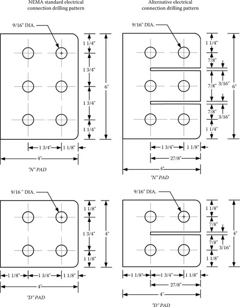
FIGURE 5.115
NEMA and alternative connection drilling patterns.
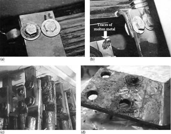
FIGURE 5.116
(a) Improper installation with large thin flat washers and no Belleville washers. (b) Joint overheating and products of melting. (c) Unacceptable selection of joint hardware and improperly assembled joints. (d) Tin-plated busbar showing the results of an excessive heating and formation of a thick insulating layer.
5.11 Accelerated Current-Cycling Tests (Standards)
5.11.1 Present Current-Cycling Tests
Designing accelerated tests is a very complex task requiring a complete understanding of the operation and the failure mechanisms of the electrical connection. The complexity of accelerated testing results from the fact that there are many unanswered questions on contact phenomena still not fully explained within the limits of present knowledge which can result in misleading conclusions. A review of the existing current-cycling tests used throughout the world to characterize the connector performance and contact materials reveals that practically every industrial country has its own testing procedure. In some countries, the United States for example, there are several organizations such ANSI, IEEE, Underwriters Laboratory and military, that are involved in standardization of the current-cycling testing procedure and contact material characterization. The majority of these testing procedures are concerned with the determination of connector performance under “artificial conditions.” In other words, the performance data is obtained under accelerated/simulated conditions of one sort or another that was then used to extrapolate to the expected field conditions. Unfortunately, these extrapolations are often questionable since the presence of more than one deterioration mechanism implies that a very detailed knowledge of each deterioration process, with respect to the acceleration factors, must be known before the connector performance under field conditions can be fully assessed.
The present accelerated heat cycle tests derive the accelerated deterioration from current overload and severe ambient conditions, that is, still air. These two factors combine to produce higher body temperatures and greater contact point super-temperatures. These higher temperatures produce conditions under which deterioration mechanisms such as stress relaxation, oxidation, fretting or formation of intermetallics are enhanced. Furthermore, there are some mechanisms which may have a definite inception temperature. Connector compounds will not flow away from the contact points at lower temperatures. Chemical breakdown of the compounds at the contact may commence only at elevated body temperatures and contact super-temperatures. If this occurs there will be not only a marked reduction in the protection against oxidation but there may be corrosive attack as well. Also, if the degree of load cycling is limited by a limitation of temperature some deterioration mechanisms such as formation of intermetallics or fretting may not commence.
Existing current-cycling testing procedures are shown in Table 5.32. These procedures are based on the temperature cycles and some include application of short-circuit currents. It is clear the performance criteria differ from one standard to another. From the point of view of the connector performance these tests provide quite reliable and repeatable results on the ability of connectors to carry load-current. However, these tests suffer from several shortcomings. They are long, costly, and may not be satisfactorily related to field conditions since the mechanisms responsible for the deterioration of the connector in the laboratory under accelerated conditions may well differ from those causing the field failures. Practice has shown that most of the connectors tested according to the conditions set by these standards can easily satisfy their performance criteria, yet fail when exposed to real operating conditions. This is because these performance criteria are not based on the theories of electrical contacts but rather on arbitrarily selected testing conditions designed to simulate field conditions. Consequently, these criteria are misleading since they fail to adequately describe the state of deterioration of the conductor/connector interface, which ultimately determines the overall performance of a connection.
Measurement of the contact resistance of a connector in a cold state—as required by the standards—is marginally affected by current-cycling and, hence, misleading, since it fails to adequately describe connector performance. Continuous measurement of the contact resistance during the heating cycle provides a much better indication of the state of deterioration of the conductor/connector interface, which ultimately determines the overall performance of a connection. It is therefore very important to measure contact resistance continuously at the end of the ON (hot-resistance) and OFF cycles (cold-resistance). In order to overcome these shortcomings and examine the performance of aluminum connections under different operating conditions, a new accelerated test, radically different from the present ones, was developed and incorporated into the revised CSA C-57 standard. The test is based on the cyclic heating and cooling of a connector by a current several times higher than rated and continuous measurement of the contact resistance and temperature.
TABLE 5.32
Most Common Current-Cycling Testing Procedure Used by Utilities and Manufacturers for Evaluating the Connector Performance
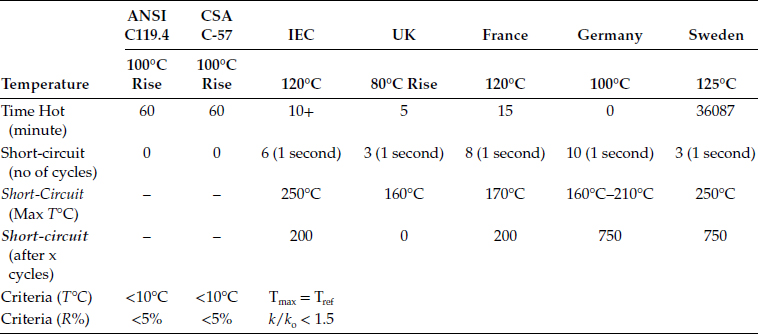
k—Connector resistance factor for each connector at any stage of measurement series,
ko—Connector resistance factor of same connector measured at cycle zero,
Tref—Temperature of reference conductor,
Tmax—Max connector temperature.
To avoid overheating of a conductor and at the same time allow the connector to attain the same temperature regime, short conductor lengths welded to large equalizers are used. This allows the temperatures of both the connectors and conductor to be kept at approximately the same level. The use of currents substantially higher than those under which connectors normally operate, is warranted since the current surges on the network are not infrequent which, in turn, can increase the current loads to very high levels thus creating necessary conditions for the accelerated deterioration of a connector. It is worth noting that Williamson [12] questioned the validity of using a higher current to accelerate the connector degradation. He argues that higher current may exceed the failure limit of the bulk temperature before self-healing process can occur. Accordingly, the connector would operate in two different modes, that is, at normal and high currents, and its inability to pass a high current gives no information at all about its reliability under normal conditions. Williamson concluded that this is an insidious pitfall inherent in the practice of accelerated testing and that in certain circumstances the use of high currents can inhibit the very phenomena on which the reliability of the connector normally depends. This argument may be applicable if the self-healing mechanism is operative. However, the evidence so far indicate that self-healing was observed in just a few instances [12] and thus cannot be universally applied. Hence, the use of higher currents is justified because their main function is to produce large differential thermal expansion at the contacting interface which, in turn, shears the conducting bridges and initiate fretting.
(In this listing Electrical Contacts = Proc. IEEE Holm Conf. on Electrical Contacts and ICEC = Proc. Int’l Conf. on Electrical Contacts)
1. R. Holm, Electric Contacts, Reprinted 4th Edition, Springer Verlag, New York (2000).
2. M. Braunovic, V.K. Konchits and N.K. Myshkin, Electrical Contacts: Fundamentals, Applications and Technology, CRC Press, Baco Raton (2007).
3. J.B.P. Williamson, “The Microworld of the Contact Spot”, Electrical Contacts-981, IIT (1981), p. 1.
4. R. Malucci, “Comparison of Model Prediction of Current Density Variations across Simulated Contact Regions”, Electrical Contacts-2010 (2010), p. 230.
5. R. Mroczkowski, “Connector Contact Surfaces—Where the Action Is”, AMP Technical Paper, pp. 268–283.
6. S. Schlegel, S. Grossman, H. Lobl, M. Hoidis, U. Kaltenborn, T. Magier, “Joint Resistance of Bolted Copper—Copper Busbar Joints Depending on Joint Force at Temperatures beyond 105°C”, Electrical Contacts-2010, p. 444.
7. R. Jackson and I. Green, “A Finite Element Study of Elasto-Plastic Hemispherical Contact Against a Rigid Flat”, J. Tribol., vol. 5, (2005), p. 343.
8. S. Wadwalkar, R. Jackson and L. Kogut, “A Study of the Elasto-Plastic Deformation of Heavily Deformed Sphaerical Contacts”, Proc. Inst. Mech. Eng.Part J. Eng. Tribol., vol. 224, (2010), p. 3.
9. A. Oberg, A. Bohlin and K.E. Olson, “The Influence of Contact Surface Preparation on the Performance of Copper and Aluminium Connectors”, Proceedings of the 16th ICEC, Loughborough, UK (1992), p. 476.
10. R.D. Naybour and T. Farrell, “Mechanical Connectors for Aluminum Cables: An Investigation of Degradation Mechanisms in Connector Clamps and Bolted Terminations”, ECRC/R426, Capenhurst, Electricity Council Research Centre (1971).
11. F. Kohlrausch, “Uber den Stationaren Temperaturzustand eines Elektrish Geheizten Leiters”, Ann. Phys., vol. 1, (1900), p. 132.
12. J.B.P. Williamson, “The Self-Healing Effect: Its Implications in the Accelerated Testing of Connectors”, Proceedings of the 10th ICEC, Budapest, Hungary (1980), p. 1089.
13. J.B.P. Williamson, “Deterioration Processes in Electrical Connections”, Proceedings of the 4th ICEC, The University of Swansea, July (1968).
14. R.L. Jackson, “Electrical Performance of Aluminum/Copper Bolted Joints”, IEEE Proc., vol. 129, Pt. C, No. 4, (1982), p. 177.
15. W.E. Campbell, “Reduction of the Rate of Film Formation on Silver and Brass by Purification of the Atmosphere”, Electrical Contacts-1977, Chicago, IIT (1977), p. 185.
16. R.F. Tylecote, “The Solid Phase Welding of Metals”, Edward Arnold, London (1968).
17. M. Braunovic, L. Pomathiod and J.-P. Bailon, “The Effect of Surface Segregation of Mg on the Contact Resistance of Al-0.5%Mg Alloy”, IEEE Trans., PHP-13, No. 3 (1977), p. 31.
18. T. Tamai, Y. Nabeta, S. Sawada, Y. Hattori, “Property of Tin Oxide Film Formed on Tin-Plated Connector Contacts”, Electrical Contacts-2010 (2010), p. 294.
19. “Crevice corrosion”, INSA, Lyon, Laboratoire de Physicochimie Industrielle, http://www.cdcorrosion.com/index-gb.htm.
20. J.-G. Zhang and X.M. Wen, “The Effect of Dust Contamination on Electric Contacts”, IEEE. Trans. CHMT, vol. 9, No. 1, March (1986), pp. 53–58.
21. M. Braunovic and M. Marjanov, “Thermoelastic Ratcheting Effect in Bolted Aluminum-to-Aluminum Connections”, IEEE Trans. CHMT, vol. 11, No. 1, (1988), p. 54.
22. E.M. Eden, W.N. Rose and F.L. Cunningham, “The Endurance of Metals”, Proc. Inst. Mech. Eng., vol. 4, (1911), p. 875.
23. G.A. Tomlison, “Rusting of Steel Surfaces in Contact”, Proc. R. Soc., vol. A115, (1927), p. 472.
24. W.E. Campbell, Symp. “Fretting Corrosion”, ASTM Spec. Tech. Publ. No. 144, (1953), p. 3.
25. R.B. Waterhouse, Fretting Corrosion, Pergamon Press, Oxford (1972).
26. N.L. Golego, A. Ya. Alyabev and V.V. Shevelya, Fretting Corrosion of Metals, Tekhnika, Kiev (1974) (In Russian).
27. P.L. Hurricks, “The Mechanism of Fretting—A Review”, Wear, vol. 15, (1970), p. 389.
28. R.D. Mindlin, “Compliance of Elastic Bodies in Contact”, J. Appl. Mech., vol 16, (1949), p. 259.
29. D. Godfrey, “Investigation of Fretting Corrosion by Microscopic Observation”, NACA Tech. Note No. 2039 (1950).
30. I.M. Feng and B.G. Rightmire, “The Mechanism of Fretting”, Lubr. Eng., vol. 9 (1953), p. 134.
31. H.H. Uhlig “Mechanism of Fretting Corrosion”, J. Appl. Mech., vol. 21, (1954), p. 401.
32. L.F. Stowers and E. Rabinowicz, “The Mechanism of Fretting Wear”, J. Lubr. Tech., vol. 95, (1973), p. 65.
33. J.F. Archard, “Contact of Rubbing Flat Surfaces”, J. Appl. Phys., vol. 24, (1953), p. 981.
34. I.A. Oding and V.S. Ivanova, “Thermoelectric Effects in Fretting Wear”, Proceedings of the International Conference on Fatigue of Metals, (1956), p. 408.
35. N.P. Suh, “The Delamination Theory of Wear”, Wear, vol. 25, (1973), p. 111.
36. R.B. Waterhouse and D.E. Taylor, “Fretting Debris and Delamination Theory of Wear”, Wear, vol. 29, (1977), p. 337.
37. E.S. Sproles Jr., D.J. Gaul and D.J. Duquette, “A New Interpretation of the Mechanism of Fretting and Fretting Corrosion Damage”, in Fundamentals of Tribology, Ed. N.P. Suh and N. Saka, MIT Press, Cambridge (1978), p. 585.
38. M. Godet, “The Third Body Approach: A Mechanical View of Wear”, Wear, vol. 100, (1994), p. 437.
39. S. Noël, D. Alamarguy, S. Correia and P. Laurat, “Fretting Behavior of Nickel Coatings for Electrical Contact Applications”, Electric Contacts-2011 (2011), p. 75.
40. A. Bouzera, E. Carvou, L. Tristani and E.M. Zindibe, “Minimum Fretting Amplitude in Medium Force for Connector Coated Material and Pure Metals”, Electrical Contacts-2010 (2010), p. 101.
41. A.J. Fenner, K.H. Wright and J.Y. Mann “Fretting Corrosion and Its Influence on Fatigue Failure”, Int. Conf. Fatigue of Metals, Inst. Mech. Eng., London (1956), p. 11.
42. A. Fairweather, F. Lazenby and A. Parker, “Development of Resistance and Microphone Noise at a Distrurbed Contact” Proceedings of the 2nd International Symposium on Electrical Contact Phenomena, Graz, May 4–6, Technische Hochschule, Graz (1964), p. 316.
43. E.M. Bock and J.H. Whitley, “Fretting Corrosion in Electric Contacts”, Electric Contacts-1974, IIT, Chicago (1974), p. 128.
44. S.J. Krumbein, “Contact Properties of Tin Plates”, Electric Contacts-1974, IIT, Chicago (1974), p. 38.
45. M. Antler, W.F. Graddick and H.G. Tompkins, “Base Metal Contacts: An Exploratory Study of Separable Connection to Tin-Lead”, Electric Contacts-1975, Chicago (1975), p. 25.
46. N. Tian, N. Saka and E. Rabinovicz, “Friction and Failure of Electroplated Sliding Contacts”, Wear, vol. 142, (1991), p. 57.
47. M. Antler and E.S. Drozdowicz, “Fretting Corrosion of Gold-Plated Connector Contacts”, Wear, vol. 74, (1981–1982), p. 27.
48. J.W. Souter and W. Staunton, “The Fretting Wear of Electrodeposited Contact Coatings”, Trans. Inst. Met. Finish, vol. 66, No. 1, (1988), p. 8.
49. M. Antler, “Fretting Corrosion of Solder-Coated Electrical Contacts”, IEEE Trans. CHMT, vol. 7, (1984), p. 129.
50. J.M. Hooyer and K. Peekstok, “The Influence of Practical Contact Parameters on Fretting Corrosion of Tin-Base Low-Level Connector Contacts”, Electric Contacts-1987, IEEE-Holm, Chicago (1987), p. 43.
51. J.H.M. Neijzen and J.H.A. Glashorster, “Fretting Corrosion of Tin-Coated Electrical Contacts”, IEEE Trans. CHMT, vol. 10, (1987), p. 68.
52. A. Lee and M. Mamrick, “Fretting Corrosion of Tin-Plated Copper Alloy”, IEEE Trans. CHMT, vol. 10, (1987), p. 63.
53. J.J. Motine and B.T. Reagor, “Investigation of Fretting Corrosion at Dissimilar Metal Interfaces on Socketed IC Device Applications”, Electric Contacts-1983, IIT, Chicago (1983), p. 61.
54. M. Braunovic and P. Gervais, “Fretting Problems in Electrical Industry”, Proceedings of the 17th Inter-Ram, Hershey (1990), p. 356.
55. M. Braunovic, “Fretting Corrosion Between Aluminum and Different Contact Materials”, Electric Contacts-1977, IIT, Chicago (1976), p. 223.
56. M. Braunovic, “Degradation of Al–Al and Al–Cu Connections due to Fretting”, Wear, vol. 125, (1988), p. 53.
57. M. Braunovic, “Fretting in Nickel-Coated Aluminum Conductors”, Proceedings of the 15th ICEC, Montreal (1990), p. 461.
58. M. Braunovic, “Effect of Different Types of Mechanical Contact Devices on the Performance of Bolted Aluminum-to-aluminum Joints Under Current-cycling and Stress Relaxation Conditions”, Electrical Contacts-1986, IIT, Boston (1986), p. 133.
59. H. Kongsjorden, J. Kulsetas and J. Sletbak, “Degradation of Electrical Contacts Caused by Oscillatory Micromotion Between the Contact Members”, Electrical Contacts-1978, Chicago (1978), p. 87.
60. H. Tian, N. Saka and E. Rabinovicz, “Fretting Failure of Electroplated Gold Contacts”, Wear, vol. 42, (1991), p. 265.
61. A. Kassman, T. Imrell and S. Jacobson, “Fretting of Powered Silver Plated Connectors in a Corrosive Environment”, Proceedings of the 17th ICEC, Nagoya (1994), p. 327.
62. M. Antler and E.S. Sproles, “Effect of Fretting on the Contact Resistance of Palladium”, IEEE Trans. CHMT, vol. 5, No. 1, (1982), p. 158.
63. M. Antler, “Electrical Effects of Fretting Connector Contact Materials: A Review”, Wear, vol. 106, (1985), p. 5.
64. R.D. Mallucci, “Dynamic Model of Stationary Contacts Based on Random Variations of Surface Features”, Electrical Contacts-1991 (1991), p. 90.
65. M.D. Bryant, “Resistance Build-Up in Electrical Connectors due to Fretting Corrosion of Rough Surfaces”, Electrical Contacts-1993, Pittsburgh (1993), p. 178.
66. C. Dang and M. Braunovic, “Metallurgical and Contact Resistance Studies of Sleeve Connectors in Aluminum Cable Splices”, IEEE Trans CHMT, vol. 13, (1990), p. 74.
67. R.L. Jackson, Private communication.
68. J.L. Johnson and L.E. Moberly, “Separable Electric Power Contacts Involving Aluminum Bus-Bars”, Electric Contacts-1975, IIT, Chicago (1975), p. 53.
69. P.J. Thiesen and K.A. Forsell, “Connector Dependent Fretting Corrosion Test System”, Electric Contacts-1979, IIT, Chicago (1979), p. 109.
70. N. Bond, “Alumiunm Contact Surfaces in Electrical Transition Interfaces”, IEEE Trans. PMP, vol. 5, No. 2, (1969), p. 104.
71. R.D. Naybour and T. Farrell, “Connectors for Aluminum Cables: A Study of the Degradation Mechanisms and Design Criteria for Reliable Connectors”, IEEE Trans. PHP, vol. 9, No. 1, (1973), p. 30.
72. L. Roullier, “Contact Interfaces in Aluminum Mechanical Joints”, Proceedings of the 2nd International Symposium on Electric Contact Phenomena, Graz, Austria, Technische Hochschule (1967).
73. M. Braunovic, “Fretting Damage in Tin-Plated Aluminum and Copper Connections”, Electric Contacts-1989, San Francisco (1989), p. 179.
74. M. Braunovic, “Effect of Fretting in Aluminum-to-Tin Connections”, IEEE Trans. CHMT, vol. 13, No. 3, (1990), p. 579.
75. M. Antler, “Tribology of Electronic Connectors: Contact Sliding Wear, Fretting and Lubrication”, in Electrical Contacts: Principles and Applications, Ed. P.G. Slade, Marcel Dekker, New York (1999), p. 309.
76. A. Kassman and S. Jacobson, “Surface Damage, Adhesion and Contact Resistance of Silver Plated Copper Contacts Subjected to Fretting Motion”, Wear, vol. 165, (1993), p. 227.
77. M. Braunovic, “Fretting in Electrical/Electronic Connections: A Review”, IEICE Trans., vol. E85, No. 1, January (2002), p. 1.
78. D. Gagnon and M. Braunovic, “Fretting in Copper-to-Copper Contacts Under AC and DC Current Conditions”, IEEE Trans. CPT., vol. 24, (2001), p. 378.
79. M. Braunovic, “Aluminum Connections: Legacies of the Past”, Electrical Contacts-1994, Chicago (1994), p. 1.
80. J.L. Queffelec, N. Ben Jemaa, D. Travers and G. Pethieu, “Materials and contact shape studies for automobile connector development”, Proc. 15th ICEC, Montreal (1990), p. 225.
81. J. Ambier and P. Perdigon, “Fretting Corrosion of Separable Electrical Contacts”, Electric Contacts-1984, IIT, Chicago (1984), p. 105.
82. C.R. Dixon and F.G. Nelson, “The Effect of Elevated Temperature on Flash-Welded Aluminum-Copper Joints”, Trans. AIEE II, vol. 78, (1960), p. 491.
83. E.R. Wallach and G.J. Davis, “Joint Resistance and Current Paths in Heat-Treated Aluminum/Copper Solid-State Welds”, Met. Sci., March (1977), p. 97.
84. E.R. Wallach and G.J. Davis, “Mechanical Properties of Aluminum-Copper Solid-Phase Welds”, Met. Tech., April (1977), p. 183.
85. D.M. Rabkin, V.R. Ryabov, A.V. Lozovskaya and V.A. Dovzhenko, “Preparation and Properties of Copper-Aluminum Intermetallic Compounds”, Sov. Powder Met. Ceram., vol. 8, No. 92, (1970), p. 695.
86. M.M. Nakamura, Y. Yonezawa, T. Nakanishi and K. Kondo, “Durability of Al–Cu Hot-Pressure Welding Joints”, Wire J., April (1977), p. 71.
87. N.A. Gjosten, Diffusion, ASM, Metals Park, OH (1973), p. 41.
88. M. Runde, “Material Transport and Related Interfacial Phenomena in Stationary Aluminum Contacts”, PhD Thesis, The Norwegian Institute of Technology (1987).
89. A.M. Gusak and K.P. Gurov, “Kinetics of Phase Transformations in a Diffusion Zone During Interdiffusion Phase Formation”, Phys. Met. Metallogr, vol. 53, No. 5, (1982), p. 12.
90. V.N. Pimenov, K.P. Gurov, K.I. Khudyakov, S.S. Dol’nikov, R.A. Milievskii, V.S. Khlomov and Yu.G. Miller, “Effect of Electrical Current on the Phase Formation in the Diffusion Layer”, Fiz Khim Obrabotki Materialov, vol. 1, (1978), p. 107 (in Russian).
91. M. Braunovic and N. Alexandrov, “Intermetallic Compounds in Aluminum-to-Copper Electrical Interfaces: Effect of Temperature and Electric Current”, IEEE Trans. CPMT-17, Part A, vol. 17, (1994), p. 78.
92. R. Timsit, “Electrical Instabilities in Stationary Electrical Contacts: Al-Plated-Brass Junctions”, IEEE Trans. CHMT, vol. 11, No. 1, (1988), pp. 43–45.
93. J.A. Rayne and C.L. Bauer, “Effect of Intermetallic Phase Formation on Electrical and Mechanical Properties of Flash-Welded Al–Cu Couples”, Proceedings of the 5th Bolton Landing Conference on Weldments, General Electric (1979), p. 353.
94. H.B. Huntington, “Electromigration in Metals” in Diffusion in Solids: Recent Developments, Ed. A.S. Nowick, and J.J. Burton, Academic Press, New York (1974), Chapter 6.
95. A. Sorzoni, B. Neri, C. Caprile and F. Fantini, “Electromigration in Thin-Film Interconnection Lines: Models, Methods and Results”, Mater. Sci. Rep., vol. 7, No. 4–5, (1991), p. 143.
96. M. Runde, E. Hodne and B. Totdal, “Experimental Study of the Conducting Spots in Aluminum Contact Interface”, Electrical Contacts-1986, Chicago (1986), p. 213.
97. J. Aronstein, “Electromigration Failure of Aluminum Contact Junctions”, Electrical Contacts-1995, Montreal (1995), p. 10.
98. J. Aronstein, “AC and DC Electromigration in Aluminum Contact Junctions”, Electrical Contacts-1996, Chicago (1996), p. 311.
99. R.D. Naybour and T. Farrell, “Degradation Mechanisms of Mechanical Connectors on Aluminum Conductors”, Proc. IEE, vol. 120, No. 2, (1973), p. 273.
100. R. Atermo, “A Method for Testing Compressive Relaxation in Aluminum Wire Conductors”, Wire J., September (1973), p. 127.
101. O.A. Troitsky and A.G. Rozno, “Electroplastic Effect in Metals”, Sov. Phys. Solid State, vol. 12, (1970), p. 161.
102. A.A. Klypin, “Creep of Metals Under the Influence of Electric Current”, Probl. Prochnosti, vol. 9, (1972), p. 35.
103. V.I. Stashenko, O.A. Troitskii and V.I. Spitsyn, “Action of Current Pulses on Zinc Single Crystals During Creep”, Phys. Status Solidi A, vol. 79, (1983), p. 549.
104. O.A. Troitskii and V.I. Spitsyn, “Investigation of the Electroplastic Deformation of a Metal by the Method of Stress Relaxation and Creep”, Sov. Phys. Dokl., vol. 21, No. 2, (1976), p. 111.
105. O.A. Troitskii and V.I. Stashenko, “Stress Relaxation Investigation of the Electroplastic Deformation of a Metal”, Phys. Met. Metallogr, vol. 47, (1979), p. 149.
106. O.A. Troitskii, V.I. Spitsyn and V.I. Stashenko, “The Effect of an Electric Current on the Relaxation of Stresses in Crystals of Zinc, Cadmium and Lead”, Sov. Phys. Dokl., vol. 23, No. 7, (1978), p. 509.
107. O.A. Troitskii and A.G. Rozno, “Effect of Electric Current on the Plastic Deformation of a Metal”, Phys. Met. Metallogr, vol. 30, No. 4, (1970), p. 153.
108. V.P. Lebedev and V.I. Hotkrvich, “Effect of Electric Current pulses on the Low-Temperature Deformation of Aluminum”, Phys. Met. Metallogr., vol. 54, No. 2, (1982), p. 23.
109. S.K. Varma and L.R. Cornwell, “The Electroplastic Effect in Aluminum”, Scripta Met., vol. 13, (1979), p. 733.
110. O.A. Troitskii, “Effect of the Electron State of a Metal on Its Mechanical Properties and the Phenomenon of Electroplasticity”, Strength Met., vol. 9, No. 1, (1977), p. 35.
111. V.I. Spitsyn and O.A. Troitskii, Electroplastic Deformation of Metals, Nauka, Moscow, (1985), (In Russian).
112. O.A. Troitskii, V.I. Spitsyn and V.G. Ryzhkov, “Electroplastic Drawing of Steel, Copper and Tungsten”, Sov. Phys. Dokl., vol. 23, No. 11, (1978), p. 861.
113. O.A. Troitskii, “Pressure Shaping by the Application of High Energy”, Mater. Sci. Eng., vol. 75, (1985), p. 37.
114. V.I. Bazaykin, V.E. Gromov, V.A. Kuznetsov and V.N. Peretyatko, “Mechanics of Electrostimulated Wire Drawing”, Int. J. Solids Struct., vol. 27, No. 11, (1991), p. 1639.
115. O.A. Troitskii and V.I. Likhtman, “Anisotropy of Electron and -Radiation on the Deformation of Brittle Zinc Single Crystals”, Sov. Phys. Dokl., vol. 148, (1963), p. 332.
116. V.Ya. Kravchenko, “Effect of Directed Electron Beam on Moving Dislocations”, Sov. Phys. JETP., vol. 51, (1966), p. 1135.
117. K.M. Klimov, V.D. Shnyrev and N.I. Novikov, “The Electroplasticity of Metals”, Sov. Phys. Dokl., vol. 19, (1975), p. 787.
118. A.M. Roschupkin, O.A. Troitskii and V.I. Spitsyn, “Development of the Concept of the Effect of Current with High Density on the Plastic Deformation of Metals”, Sov. Phys. Dokl., vol. 286, No. 3, (1986), p. 633; (1979), p. 532.
119. K. Okazaki, H. Kagawa and H. Conrad, “A Study of the Electroplastic Effect in Metals”, Scripta Met., vol. 12, (1978), p. 1063.
120. K. Okazaki, M. Kagawa and H. Conrad, “Additional Results on the Electroplastic Effect in Metals”, Scripta Met., vol. 13, (1979), p. 277.
121. K. Okazaki, M. Kagawa and H. Conrad, “An Evaluation of the Contribution of Skin, Pinch and Heating Effects to the Electroplastic Effect in Titanium”, Mater. Sci. Eng., vol. 45, (1980), p. 109.
122. A.F. Sprecher, S.L. Mannan and H. Conrad, “On the Mechanisms for the Electroplastic Effect in Metals”, Acta Metall., vol. 34, No. 7, (1986), p. 1145.
123. H. Conrad and A.F. Sprecher, “The Electroplastic Effect in Metals”, in Dislocations in Solids, vol. 8, Ed. F.R.N. Nabarro, Elsevier (1989), p. 498, Chapter 43.
124. H. Conrad, J. White, W.D. Cao, X.P. Lu and A.F. Sprecher, “Effect of Electric Current Pulses on Fatigue Characteristics of Polycrystalline Copper”, Mater. Sci. Eng., vol. A145, (1991), p. 1.
125. H. Conrad, A.F. Sprecher, W.D. Cao and X.P. Lu, “Electroplasticity—The Effect of Electricity on the Mechanical Properties of Metals”, J. Mater., September (1990), p. 28.
126. R. Timsit, “Remarks on Recent Experimental Observations of the Electroplastic Effect”, Scripta Met., vol. 15, (1981), p. 461.
127. W.D. Cao, A.F. Sprecher and H. Conrad, “Measurement of the Electroplastic Effect in Nb”, J. Phys. E Sci. Instrum., vol. 22, (1989), p. 1026.
128. V.L.A. Silveira, M.F.S. Porto and W.A. Mannheimer, “Electroplastic Effect in Copper Subjected to Low Density Electric Current”, Scripta Met., vol. 15, (1981), p. 945.
129. V.L. Silveira, R.A.F.O. Fortes, and W.A. Mannheimer, “Modification of the Dislocation Substructure in Copper During Electroplastic Treatment”, Beitr. Elektronenmikroskop. Direktabb. Oberfl, vol. 15, (1982), p. 217.
130. M. Braunovic, “The Effect of an Electric Current on the Stress Relaxation of Aluminum Wire Conductors”, Proceedings of the 7th International Conference on Strength of Metals, ICSMA-7, Pergamon Press (1985), p. 619.
131. M. Braunovic, “Evaluation of Different Contact Aid Compounds for Aluminum-to-Copper Connections”, IEEE Trans. CHMT, vol. 15, No. 2, (1992), p. 216.
132. S.W. Melsom and H.C. Booth, “The Efficiency of Overlapping Joints in Copper and Aluminum Busbar Conductors”, J. IEE., vol. 60, No. 312, (1922).
133. E. Donati, “Overlapping Joints in Electric Furnace Circuits”, L’Energia Elettrica, vol. 12, No. 6, (1935), p. 433.
134. “Al Elastic Contact Disks”, Karl Pfisterer Techn. Bulletin, No. 2 (1991).
135. V.I. Boychenko and N.N. Dzektser, “Busbar Connections”, Energiya, 1978, (In Russian).
136. M. Braunovic, “Effect of Connection Design on the Contact Resistance of High Power Ovelapping Bolted Joints”, IEEE Trans, CPT, vol. 25, No. 4, (2002), p. 1.
137. O.B. Bron, M.G. Myasnikova, I.P. Miroschnikov and V.N. Fyodorov, “Permissible Temperatures for Electric Contacts”, Proceedings of the 10th ICEC, Budapest (1980), p. 71.
138. H. Jesvold, M. Runde and G.I. Tveite, “The Effect of Conductor Hardness on Aluminum Compression Joints”, Proceedings of the 17th ICEC, Nagoya (1994), p. 497.
139. M. Braunovic and C. Dang, “Comparative Assessment of Different Current-Cycling Procedures for Testing Power Connections”, Electrical Contacts-1997, Philadelphia (1997), p. 87.
140. “Connectors for Use between Aluminum-to-Aluminum or Aluminum-to-Copper Bare Overhead Conductors”, July 1991, ANSI C119.4-1991.
141. “Electric Power Connectors for Use in Overhead Line Conductors”, CSA C57–1966.
142. M. Braunovic, Unpublished work.
143. J.J. Schindler, R.T. Axon and R. Timsit, “Mechanical and Electrical Contact Properties of Wedge Connectors”, IEEE Trans. CPMT-A, vol. 19, (1996), p. 287.
144. M. Braunovic, “Use of Shape-Memory Materials in Distribution Power Systems”, CEA Report No. SD-294A.
145. M. Braunovic and C. Labrecque, “Shape-Memory Alloy Mechanical Contact Devices”, Electrical Contacts-1994, Chicago (1995), p. 21.
146. C. Labrecque, M. Braunovic, F. Trochu, V. Brailovski, Y.Y. Quian, T. Terriault and L.M. Schetky, “Experimental and Theoretical Evaluation of the Behaviour of a Shape-Memory Alloy Belleville Washer Under Different Operating Conditions”, Electrical Contacts-1995, Montreal (1996), p. 195.
147. A. Oberg and S. Nilsson, “Shape-Memory Alloys for Power Connector Applications”, Electrical Contacts-1993, Pittsburgh (1993), p. 225.
148. T. Waram, “Design Consideration for Shape-Memory Belleville Washers”, Raychem Tech. Doc.
149. McD. Schetky, “The Present Status of Industrial Applications for Shape-Memory Alloys”, EPRI TR, vol. 105072, (1995), p. 41.
150. M. Braunovic, “Use of Shape-Memory Materials in Distribution Power Systems”, Canadian Electricity Association, CEA Report SD-294A (1994).
151. W.F. Bonwitt, “An Experimental Investigation of the Electrical Performance of Bolted Aluminum-to-Copper Connections”, AIEE Trans., vol. 67, (1948), p. 1208.
152. D.C. Hubbard, R.W. Kunkle and A.B. Chance, “Evaluation of Test Data in Determining Minimum Design Requirements for Aluminum-Copper Connectors”, AIEE Trans., vol. 73, (1954), p. 616.
153. N. Bond and F.L. McGeary, “Nickel Plating for Improved Electrical Contact to Aluminum”, IEEE Trans., IA-9, (1973), p. 326.
154. C.L. Bauer and G.G. Lessmann, “Metal-Joining Methods”, Annu. Rev. Mater. Sci., vol. 6, (1976), p. 361.
155. A. Kassman-Rudolphi, “Tribology of Electrical Contacts—Deterioration of Silver Coated Copper”, Doctorate Dissertation, Upsala University, Sweden (1996).
156. R.L. Jackson, “Significance of Surface Preparation for Bolted Aluminum Joints”, Proc. IEE, vol. 126, Pt. C, No. 2, (1981), p. 45.
157. J. Lefebre, J. Galand and R.M. Marsolais, “Electrical Contacts on Nickel Plated Aluminum: The State of the Art”, Electrical Contacts-1990, Montreal (1990), p. 454.
158. J. Aronstein, “Evaluation of a plated Aluminum Wire for Branch Circuit Applications”, Electrical Contacts-1987, Chicago (1987), p. 107.
159. T.K. Hare, “Investigation of Nickel-Plated Aluminum Wire Using Analytical Electron Microscope”, Electrical Contacts-1987, Chicago (1987), p. 113.
160. J.F. Bruel and A. Carballeira, “Durabilité des Contacts Électriques en Aluminum”, Proc. SEE, December (1986), p. 139.
161. M. Braunovic, “Evaluation of Different Platings for Aluminum-to-Copper Connections”, IEEE Trans. CHMT, vol. 15, No. 2, (1992), p. 204.
162. M. Antler, “The Lubrication of Gold”, Wear, vol. 6, (1963), p. 44.
163. W.O. Freitag, “Wear, Fretting and the Role of Lubricants in Edge Connectors”, Electrical Contacts-1975, IIT (1975), p. 17.
164. W.E. Campbell and M.J. Trcka, “Development of Lubricant Composition for Sliding Switch Contacts”, Electrical Contacts-1974, IIT, Chicago (1974), p. 258.
165. W.H. Abbott and J.H. Whitley, “Lubrication and Environmental Protection of Alternatives to Gold for Electronic Connectors”, Electrical Contacts-1975, IIT, Chicago (1975), p. 9.
166. A. Huber, “The Lubrication of Electrical Contacts”, Proceedings of the 13th ICEC-1986, Lausanne, Switzerland (1986), p. 447.
167. M. Braunovic, “Evaluation of Different Types of Contact Aid Compounds for Aluminum-to-Aluminum Connectors and Conductors”, IEEE Trans. CHMT, vol. 8, No. 3, (1985), p. 313.
168. Multilam Contact Elements, http://www.multi-contact-usa.com/products/multilamline/1.
169. A.S.M. Handbook Volume 6 “Welding, Brazing and Soldering” p. 164.
170. “Xeconex-Implosive Connectors”, Implo Technologies Inc. Tech, Bulletin, (1997).
171. P. Nguyên-Duy, S. Boisvert, C. Lanouette and Y. Blanchette, “Optimisation des plages de contact de l’ensemble marteau-mâchoire des sectionneurs GEC Alsthom type BCVB 735 kV 4000A2”, Technical Report IREQ 96-013 (1996).
172. M. Braunovic, “Effect of Different Types of Mechanical Contact Devices on the Performance of Bolted Aluminum Joints Under Current Cycling and Stress Relaxation Conditions”, Proceedings of the 32nd IEEE Holm Conference on Electrical Contacts (1986), p. 133.
173. D.W. Jondhal, M.L. Rockfield and G.M. Cupp, “Connector Performance of New vs Service-Aged Connector. Part I”; J.D. Sprecher, M.L. Rockfield and T. Nobelfer, “Connector Performance of New vs Service-Aged Connector. Part II”, Proceedings of the 1994 Power Engineering Society IEEE Transactions and Distribution Conference, 94CH3426-0 (1994).
174. J. Sprecher, B. Royce, “Higher Load Demands New Tap Connector Practices,” Electrical World, vol. 208, 48–55, 1994.
175. M. Braunovic, “Reliability of Underground Connections”, Canadian Electricity Association Report, CEA 227 D 916 (1997).
176. B.W. Callen, B. Johnson, P. King, R.S. Timsit and W.H. Abbott, “Environmental Degradation of Utility Power Connectors in a Harsh Environment”, Electrical Contacts-1999 (1999), p. 63.
177. M. Braunovic, V.V. Izmailov and M.V. Novoselova, “A Model for Life Time Evaluation of Closed Electrical Contacts”, Electrical Contacts-2005 (2005), p. 217.
178. V.V. Izmailov, “Conductivity of Long-Term Closed Electrical Contacts”, Proceedings of the 10th International Conference on Electrical Contact Phenomena, Budapest (1980), p. 93.
179. E. Takano and K. Mano. “The Failure Mode and Lifetime of Static Contacts”. IEEE Trans. Pt. Mater. Pack., vol. 1, (1968), p. 51.
180. W.J. Buehler, J.V. Gilfrich and K.C. Weilley, “Shape-Memory Effect in Ni-Ti Alloys”, J. Appl. Phys., vol. 34, (1963), p. 1457.
181. “Use of Shape Memory Alloys in High Reliability Fastening Applications”, Intrinsic Devices Inc., http://www.intrinsicdevices.com.
183. “Shape-Memory Temperature Indicator”, Furukawa Electric Co., Jap. Patent No. 2-70218 (1990).
184. “Shape-Memory Temperature Indicator to Monitor Overheating of Electric Power Cables”, Tohoku Denryoku KK-Fujikura Ltd., Jap. Patent No. 3-201313 (1991).
185. L. Lischina, Private communication.
186. M. Ashby, A. Evans, N.A. Fleck, L.J. Gibson, J.W. Hutchinson and H.N.G. Wadley, Metal Foams: A Design Guide, Butterworth (2000).
187. M. Braunovic and S. Vatchiantz, Unpublished work.
188. S. Vatchiantz and N. Manukyan, “Structure Dévelopment in Aluminum Foam Manufactured by Hot Rolling”, SMA ICAA11, Conference, Japan (2010).
189. J. Jerz, P. Simancik, M. Bortel, S. Kubo and J. Kovacik, “The Design of Lightweight Armour Sheets”, in Proceedings of the International Conference on Cellular Metals and Metal Foaming Technology, Ed. J. Banhart and N.A. Fleck, MIT Publishing, Bremen (1999), p. 235.
190. M. Braunovic and D. Gagnon, “Aluminum Foam Transition Washer for Power Applications”, IEEE Holm Conference Proceedings (2008), p. 258.
191. Ecocontact http://www.amcetec.com/ecocontact.