
Tribology of Electronic Connectors: Contact Sliding Wear, Fretting, and Lubrication
– Ovid
CONTENTS
7.2.2.1 “Wiping” Contaminant from Contact Surfaces
7.2.2.5 Gold Platings: Intrinsic Polymers and Junction Growth
7.2.2.6 Electroless Gold Plating
7.2.5 Delamination and Subsurface Wear
7.2.6 Effect of Underplate and Substrate
7.2.7 Electrodeposited Gold: Relationship of Wear to Underplate Hardness
7.2.7.1 Hardener Metal Content
7.3.3 Static versus Dynamic Contact Resistance
7.3.4 Field and Laboratory Testing Methodologies
7.3.4.1 Generation of Fretting Displacement
7.3.4.2 Determination of Contact Resistance
7.3.5.2 Metals Having Little or No Film-Forming Tendency
7.3.5.3 Non-Noble Metals/Fretting Corrosion
7.3.5.4 Frictional Polymer-Forming Metals
7.3.5.5 Dissimilar Metals on Mating Contacts
7.3.6.2 Palladium-Based Systems
7.3.6.3 Tin and Tin-Lead Alloy Systems
7.3.6.4 Role of Underplate and Substrate
7.3.11 Surface Finish and Contact Geometry
7.3.12 Material Transfer, Wear, Film Formation, and Contact Resistance
7.3.12.1 Summary of Physical Processes
7.4.2.1 Principles of Metallic Film Lubrication
7.4.2.2 Sliding and Wiping Contacts
7.4.3.2 Some Fundamental Properties of Lubricants
7.4.3.4 Types of Fluid Lubricants: A Sliding Contact Investigation
7.4.3.5 Control of Fretting Degradation
7.4.4 Grafted and Self-Assembled Lubricant Layers
7.4.5 Greases and Solid Lubricants
Sliding wear and fretting are key determinants of the performance of connectors, printed circuit boards with edge contacts, switches, instrument slip rings, and other electrical components. Unlike the technology of relays and circuit breakers, which are designed for current make and break and where the physics of the arc and erosion are the focus of contact research, the technology of connectors is concerned with metal transfer, material removal, friction, and electrical noise. Connector life, cost, and especially reliability are determined in large part by sliding wear and fretting phenomena.
In this chapter, we discuss the tribology of electrical contacts under three headings: sliding, fretting, and lubrication. In electrical connections, wear is generally associated with separable rather than permanent interfaces because surface damage is often visible to the naked eye after separation. Although interfacial defects introduced by extensive mechanical wear are usually detrimental to the function of an electrical contact, there are many instances where a limited amount of wear actually benefits an electrical connection. For example, initial sliding in a separable connection often disrupts electrically insulating surface films that interfere with electrical current flow and is thus beneficial to contact performance. Over the years, a number of wear mechanisms have been identified and are described in detail in the literature [1,2].
As this chapter reviews tribological data recorded over many years, some of which were obtained well before adoption in the scientific literature of SI units, we have opted to reproduce the units used in the original publications. Conversion of earlier data to SI units would have necessitated a great deal of reworking of graphs and tables, which we decided was not necessary to fulfill the major objective of the present review. Thus, the units of contact force will include gf, kgf, N, and so on. Similarly, units of length will include mm, cm, m, and so on.
When two surfaces are brought together, they touch at the tip of surface asperities (i.e., at small contact spots or a-spots) and the area of true contact is small. This area is determined by the contact force and the microhardness of the contacting materials [3,4,5,6,7]. When the surfaces slide over each other at a relatively low speed, mechanical damage to the surfaces stems from the action of one of several major wear mechanisms. Whatever the wear mechanism, mechanical wear leads to the removal of material from surface asperities in contact with each other. The inescapable consequence of this asperity interaction is that the amount of material removed from a sliding surface depends on the area of true contact AC. Since AC = F/H where F is the mechanical contact load and H is the microhardness of the metal, as described in Equation 1.10 in Chapter 1, the amount W of material worn off a surface over a sliding distance s is
(7.1) |
where K is the wear coefficient associated with the materials in sliding contact. Theoretical support for Equation 7.1 shows that the wear coefficient is associated with the probability that an interaction between asperities leads to the production of a wear particle [8,9,10]. It also should be noted that Equation 7.1 applies to the steady state and does not address run-in wear, which has been found usually to dominate the sliding of many contact devices. Separable connectors as they are usually used do not attain equilibrium wear because the total sliding distance in their lifetime is relatively small.
Wear phenomena that have been observed in practical devices are complex and resist simple categorization. For example, mechanical debris produced as a result of adhesive transfer causes secondary wear by abrasion. Wear mechanisms that were considered to be significant in the early days of electrical contact research, such as Holm’s “molecular wear” and “interlocking” [11], have fallen out of favor. Nevertheless, it is convenient to after relevant describe the wear of metallic contacts by processes that today are recognized to be relevant to electrical connectors: adhesion, abrasion, brittle fracture, fretting, and, in special cases, subsurface wear with layered materials and delamination. There are still other categories of sliding wear phenomena, especially outside of the electrical contact field such as chemically induced wear.
Adhesive wear occurs when sliding surfaces experience metal transfer, and is generally characterized by the generation of fine particles from one or both of the surfaces. These particles may come off the surface from which they are formed and may either adhere to the mating surface as a transfer layer or accumulate as loose debris on the sliding surfaces. Adhesive wear stems initially from adhesive bonding between the touching surface asperities, under conditions where this bonding is stronger than the cohesive strength of the metal.
The adhesive wear mechanism is illustrated schematically in Figure 7.1 [2]. It is initiated when localized adhesion occurs at contact spots between sliding surfaces as illustrated in Figure 7.1a. This is followed by repeated transfer of material from one asperity to the other and by growth of the transferred material (Figure 7.1b through d). Transferred particles eventually detach themselves and are subsequently flattened and dispersed as loose wear debris (Figure 7.1e). The rate of debris generation increases where sliding motion consists of reciprocating displacements over the same wear track. Under conditions where sliding motion is unidirectional and the contact load is sufficiently large, adhesive wear in chemically clean sliding interfaces can lead to so-called prow formation, as described later. For non-noble materials, metal debris generated by adhesive wear undergoes oxidation to form highly electrically insulating material.
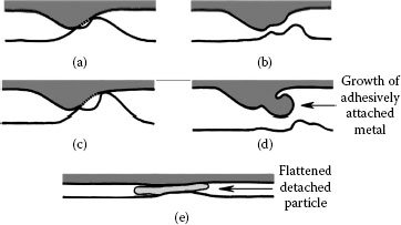
FIGURE 7.1
Schematic representation of adhesive wear in a sliding interface: (a) localized adhesion between contacting surface asperities during sliding, (b) transfer of material from one asperity to the other, (c) repetitive adhesion process, (d) growth of transferred particles, and (e) particle detachment and subsequent debris flattening.
7.2.2.1 “Wiping” Contaminant from Contact Surfaces
Although adhesive wear is generally deleterious to the long-term contact performance, it can also act to reduce rather than increase contact resistance for cases of weakly adhering material in a sliding interface, such as organic deposits. In such cases, adhesive wear reduces contact resistance by displacing electrically insulating layers such as oxides, sulfides, and other materials formed from chemical reactions with air or environmental pollutants, without appreciable removal of the underlying metal. This action is often identified as “wipe” cleaning motion [12,13]. “Wiping” is usually recommended as a first step in generating low contact resistance in separable electrical connections such as pin–socket contacts. This precaution is recommended even for gold-plated contacts to enhance contact reliability, since gold has a tendency to absorb thin carbonaceous layers [14,15]. An example of organic contamination on a gold surface exposed to laboratory air for a few days, after having been cleaned chemically, is illustrated in Figure 7.2. The typical effect of wipe on contact resistance between contaminated gold contacts is illustrated in Figure 7.3 [13]. The graphs show the decrease in contact resistance with increasing contact load when the gold surfaces are stationary and are subsequently set into sliding motion. The data of Figure 7.3a relate to the case where the surfaces were not severely contaminated, thus showing a small resistance decrease during sliding. In contrast, the data of Figure 7.3b show that the contamination of the flat gold surface was so severe that the contact was essentially open at a contact load as large as ~1.2 N. However, the contact resistance decreased rapidly after sliding motion was initiated. The sliding motion was clearly effective in squeezing contaminant material out of a-spots. Continuing wipe-travel led to a further decrease in contact resistance as additional contaminant was pushed out to the side of the wear track.
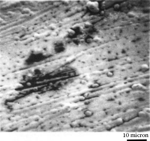
FIGURE 7.2
Dark areas are organic contamination on an initially clean gold surface after exposure to laboratory air for several days. Scanning electron microscope (SEM) at low (2 kV) beam energy.
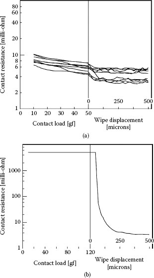
FIGURE 7.3
Contact resistance versus normal contact load and versus wipe distance for a gold probe sliding on (a) a contaminated gold-plated surface and (b) a highly contaminated gold-plated surface. (After, IH Brockman et al., IEEE Trans. Components, Hybrids and Manuf. Technology, CHMT-11: 393–400, 1988 [13].)
Several researchers in the 1950s [16,17,18] observed that many systems operate at widely different rates of adhesive wear, called mild and severe, and that the scale of wear may change in a narrow range of load, as in Figure 7.4. Below the transition load with base metals, wear debris is usually oxidized and finely divided (10−4–10−2 mm); above it, debris is largely metallic and coarse (10-1–1 mm). The transition occurs due to the increasingly rapid rate of formation of wear particles with increasing load or from lubrication failure. With oxide-free noble metals, sliding is in the severe regime at all loads when the surfaces are very clean; in practice transition loads do occur, but they seem to be related to the removal of adventitious contaminants during sliding. Such materials, as in Figure 7.2, can be strikingly protective; but when repeat-pass transversals occur on too short a timescale for the contaminant to be renewed, the transition to severe wear occurs. For this reason, the durability of unlubricated separable connector contacts is related to the rate of mating and unmating [19].
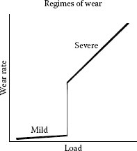
FIGURE 7.4
Regimes of wear.
The transition load in air for clean electrodeposited cobalt–gold is about 25 gf and decreases to about 5 gf for clad Au99Co1, as measured using a gold hemispherical dimple sliding on a flat surface in laboratory sliding experiments.
At relatively large contact loads (say > 100 gf) and if sliding occurs in one direction or is reciprocating over a sufficiently long distance, adhesive wear of most clean contact metals proceeds by a severe adhesive mechanism called prow formation [20,21]. It may be described phenomenologically as follows for contacts of the same material: when the mating bodies are of different size, there is net metal transfer from the part with the larger surface to the part with the smaller surface, for example, from flat to rider in a rider–flat apparatus. The process is similar to that illustrated in Figure 7.1, but the debris particles are larger due to the long sliding distance in the same direction. A lump of severely work-hardened metal (the prow) builds up and in turn wears the flat by continuous plastic shearing or cutting, while the rider does not wear. Prows then detach from the rider either by back-transfer to the flat or as loose debris. If the rider always traverses virgin metal, prow formation continues indefinitely. This is shown schematically in Figure 7.5. When contact members of the same material are identical in size and shape, the initial prow can come from either member. However, once transfer occurs, the receptor then becomes the rider and the opposing surface wears. With dissimilar metals, prows form even when the flat is harder than the rider, provided this difference is not greater than a factor of about 3. Friction and contact resistance characteristics of the system are determined by the prow metal; thus, a palladium rider sliding on a gold flat behaves as does gold on gold, while a gold rider on palladium slides like palladium on itself [22].
Prows from soft ductile metals can be observed with the unaided eye (the size of prows appears to be roughly inversely related to hardness), examples of which are given in Figures 7.6 and 7.7. Prow formation occurs with gold, palladium, palladium–nickel and palladium–silver alloys, platinum, silver, copper, copper–beryllium alloys, phosphor bronzes, lead, aluminum, bismuth, iron, titanium, and many other metals. Metals that do not work-harden, such as indium at room temperature, fail to form prows [23]. This is because prows must become harder than the flat by metalworking in order to wear the latter, particularly by cutting. Tin–lead (50/50) alloy appears to be a special case; prows from it have been found [20] to become work-softened (the Knoop Hardness at 25 gf (KHN25) was found to vary from 0.6 × 10² to 0.9 × 10² N mm−2, compared with 1.9 × 10² N mm−2 for the initial material). Perhaps there is an initial hardening followed by softening as the prow continues to be worked while it is between the contact members. Prows have been found to be layered [24], as shown in Figures 7.6f and 7.7. A number of mechanisms have been proposed for the formation of prows [20,21,25], but none has yet been confirmed experimentally.
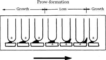
FIGURE 7.5
Prow formation mechanism (schematic). Letter “a” designates the surface to which prow is attached. Arrow indicates direction of movement of flat.
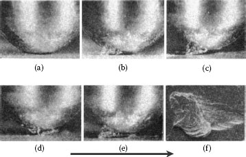
FIGURE 7.6
Prow formation mechanism for a rider, 3.2 mm in diameter, sliding on a flat specimen. Solid gold contacts, 500 gf load: (a) start of run; (b) well-developed prow; (c and d) loss of portion of prow by back-transfer to flat; (e) newly formed prow; and (f) prow consisting of overlapping thin layers of metal back-transferred to flat. The arrow indicates the direction of movement of the flat. (After M Antler, Wear, 7: 181–204, 1964 [20].)
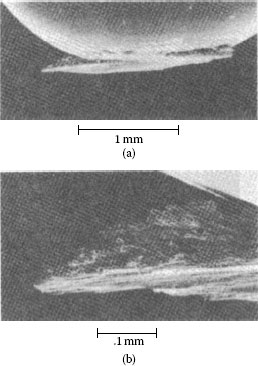
FIGURE 7.7
SEM micrograph of gold rider with adherent prow after unlubricated sliding against solid gold flat. Note the layered structure of the prow. Conditions: 300 gf, 500 passes, reciprocation. (After H Fry, HG Feller, Prakt Metallographie 9: 182–197, 1972 [24].)
When the rider traverses the same track repetitively in the same direction, or in reciprocating motion over a large displacement, prow formation eventually ceases and is replaced by “rider wear”, a mechanism in which the smaller contact surface wears. This occurs primarily by transfer to the flat with some loose particle formation; in rider wear, the flat may gain mass relatively rapidly after an interval of mass loss. As explained earlier, the initial mass loss stems from occasional attachment (initially) of prows or particle debris to the rider. The transition to a mass gain mode is due to the accumulation of back-transfer prows to the flat. This back-transfer also causes an increase in the effective surface hardness of the flat to a level of extreme work-hardening along the entire wear track. When the surface of the wear track on the flat reaches the hardness of prows, wear of the flat effectively ceases and the rate of rider wear increases rapidly.
Experimental observations indicate that there is an initial roughness of the flat above which prow formation does not occur. For pure gold, the critical roughness is in the range of 0.6–1.3-μm center line average (CLA) at 100 gf [26]. The harder and less ductile the metal, the smaller is the critical roughness, which may explain why prow formation is unlikely to occur with rhodium, ruthenium, equiatomic tin–nickel electrodeposit, and other hard brittle materials. It has been argued [27,28] that adhesive wear is affected by the mutual solubility of the materials in the sliding interface, whereby higher mutual solubility leads to higher adhesion and hence to increased wear rates. However, investigations of sliding gold surfaces on platinum group metals (low mutual solubility with gold) did not support this premise [29].
7.2.2.5 Gold Platings: Intrinsic Polymers and Junction Growth
Adhesive mechanisms dominate the wear rate of gold electrodeposits in high-reliability electrical connectors. Much of the work on adhesive wear in gold electrodeposits has been conducted with practical connector components. A recurring theme in this work has been the identification of deposition conditions and gold composition that optimize wear resistance of the electrodeposit [26,30,31,32,33].
The fundamental reasons for differences in wear behavior in different gold electrodeposits were not understood for a long time. When electrodeposited hard golds became available, it seemed that the resistance of these plates to adhesive wear relative to that of the soft pure gold deposits could be attributed to hardness. It later became apparent that this explanation was incomplete, because tests using wrought (hardened) gold alloys of hardness comparable with that of electroplated golds (e.g., from cyanide-base bath) showed the wrought alloys to be inferior [34]. Observations that a relatively pure hard gold such as metal-worked 24-karat hard gold wears poorly further emphasized the inadequacy of attributing wear resistance solely to hardness. At this historical juncture, one potential explanation for the superior durability of the cyanide gold plates was a return to an early suggestion [34] that codeposited polymeric materials [35] in the cobalt (and nickel) golds act as lubricants to mitigate wear. Despite some experimental evidence that conflicted with this explanation [36], the cause of differences in the relative wear resistance of gold electrodeposits was eventually elucidated via work that focused initially on cobalt-hardened gold.
It was confirmed that cobalt–gold electroplates deposited from cyanide baths include polymer particles consisting in part of a complex cobalt cyanide compound [35]. The particles range in average dimensions from 2 nm to 7 nm and are uniformly distributed in the gold deposit [37]. Some polymer particles may be larger than this [38]. These observations are in general agreement with a later investigation that concluded [39] that a significant fraction (perhaps a dominant fraction) of the cobalt in cobalt-hardened gold characterized by superior resistance to adhesive wear is present in the form of intrinsic polymers rather than in solid solution. The experimental evidence indicates that the metallurgical structure, the hardness, and the ductility of gold electrodeposits are strongly coupled to the composition, dimensions, and distribution of the codeposited material. Observations indicate that the most adhesive wear-resistant deposits are those characterized by low ductility, for example, with elongations less than 1%. In addition to acid bright cobalt-hardened gold, nickel-hardened gold plates containing 0.28 wt% nickel and cobalt-hardened gold containing 1.3 wt% cobalt plus 0.55 wt% indium have similar durability [26] and comparable brittleness. The role of polymers in cyanide nickel-hardened gold plates is presumed to be similar to that in the cobalt-hardened version.
It is possible to understand the correlation of low ductility with increased resistance to adhesive wear in terms of fundamental properties of contact interfaces and, specifically, in relation with the phenomenon of junction growth. This phenomenon has been found to occur ([9], p 56) where adherent surface asperities undergo tangential stress in a sliding interface. In these situations, large increases in the area of asperity contact can occur before the junction shears, particularly with ductile materials, as shown schematically in Figure 7.8. The formation of prows with attendant transfer and their eventual loss to form loose debris is closely related to junction growth, since a prow in the initiation and growth stage can be considered to be a single large junction. A material that is resistant to adhesive wear must then be characterized by a capability to resist junction growth. Greenwood and Tabor [40] confirmed the validity of this premise by modeling junctions that simulate perfect adhesion. Sheets of metal were V-notched at opposite sides, then sheared. Brittle materials, like work-hardened copper, gave little transfer, while a ductile metal, lead, produced a large fragment akin to a prow.
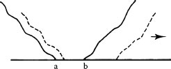
FIGURE 7.8
Schematic representation of junction growth. The normal load deforms the asperity so that contact occurs along ab. When a tangential stress is imposed in the direction of the arrow, the junction grows, as shown by the dashed lines, and the two surfaces move together slightly.
In summary, the experimental data reviewed in the above paragraph suggest that an interplay of three factors controls adhesive wear. In order to minimize adhesive wear, the contact surfaces should have the following properties:
• Be hard so as to limit the area of initial contact.
• Be characterized by low ductility to limit junction growth.
• Be lubricated to inhibit asperity adhesion.
Thus, high hardness alone, with or without codeposited polymers, is insufficient to provide good adhesive wear resistance, while hardness coupled with low ductility enhances wear resistance. The efficacy of contact lubricants in reducing wear in ductile load plate may be understood as due to compensating for the low wear resistance of ductile gold plates, both hard and soft, by mitigating adhesion and hence minimizing junction growth [41]. The action of lubricants is discussed in greater detail in Section 7.4.
7.2.2.6 Electroless Gold Plating
Since the mid-1990s, Electroless Nickel and Immersion Gold (ENIG) plating has been used in many electronic components as a metal finish alternative to gold electroplate. An ENIG layer is formed by the deposition of electroless nickel–phosphorus on a catalyzed copper surface followed by a thin layer of immersion gold. The specification covering ENIG requires 3–6 μm of nickel–phosphorus and 0.05–0.1 μm of immersion gold. ENIG is a versatile surface finish and was introduced initially as a viable surface finish on printed circuit boards (PCBs) for surface-mounting microchip packages. The gold layer thickness is about 0.1 μm since the main original objective of the gold was to protect the underlying nickel from oxidizing and becoming difficult to solder. The use of ENIG is being extended to provide a gold coating on contact surfaces of an increasing number of electrical connectors because the deposition process is relatively rapid and inexpensive. This application of ENIG has often proven unsatisfactory because the maximum gold layer thickness achievable is 0.1–0.2 μm, and gold layers of this thickness are not necessarily impervious to air and environmental contaminants and generally do not pass the requirements of a “classic” porosity test. ENIG layers on connectors are thus prone to pore corrosion. In addition, the ENIG deposition process often leads to the formation of black deposits stemming from corrosion of the underlying nickel during deposition and leading to poor adhesion of the ENIG layer to the substrate [42,43,44]. Properties of ENIG coatings will be addressed in greater detail in Chapter 8.
In abrasive wear, material is removed or displaced from a surface by hard particles. In electrical contacts, abrasion may be characterized by a qualifying terms: two-body abrasion and three-body abrasion as illustrated in Figure 7.9. Two-body abrasion is caused by hard particles that are strongly attached to one surface, such as hard precipitates on the surface of an alloy, whereas three-body abrasion stems from hard particles such as sand trapped in a sliding contact and free to move around in the interface.
A simple model for abrasive wear involves the removal of material by plastic deformation as illustrated in Figure 7.10. Consider the action of a large number of abrasive particles with each represented as a cone of semi-angle θi dragged across the surface of a ductile material to form a groove. In accordance with Figure 7.10b, the width of the groove generated by the ith particle is 2ai where ai is the cone radius at the top of the groove of depth Di. If Fi is the average normal applied force on the ith particle and σ is the maximum mechanical stress on the area , then Fi is estimated as
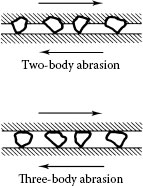
FIGURE 7.9
Schematic illustrations of two types of abrasion: two-body and three-body abrasions.
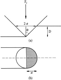
FIGURE 7.10
Simple abrasive wear model in which a cone removes material from a surface: (a) elevation view of a conical abrasive particle forming a groove in a substrate and (b) plan view of the abrasive particle at a distance D from its apex.
(7.2) |
Since each hard particle is pushed into the surface and deforms it plastically, we estimate σ ≈ H where H is the hardness of the worn material. In the simple picture that the volume of material removed from a path of length L is , where ε is a probability of removal, the wear rate qi defined as the material volume displaced per unit sliding distance by each particle is
since Fi is proportional to the total applied force F as . Summing over all abrasive particles, the total wear rate is , which reduces to
(7.3) |
where .
Thus, K is a constant that depends on material properties (via the parameter ε) and the geometry of the abrasive particles. It is noteworthy that Equation 7.3 is identical with Equation 7.1 that was derived on the basis of a simpler model than that of Figure 7.10 [5,6,7]. In electrical junctions, abrasion occurs either through the intentional introduction of hard particles into interfaces to abrade insulating surface layers such as oxide films or through the ingress of free-moving foreign hard particles such as sand. For these reasons, abrasive wear in electrical contacts arises largely from three-body abrasion. The mechanics of abrasive wear and the considerable volume of experimental data related to this subject are provided by Rabinowicz [1], Hutchings [2], and Suh [45].
Abrasive particles are intentionally introduced in aluminum connectors, and particularly aluminum power connectors, to abrade aluminum oxide surface films and promote the formation of metal–metal contacts in electrical connections involving aluminum. In these applications, the abrasive medium often consists of particles of a hard metal such as steel or ceramic powder suspended in a lubricant or mixed into a grease. The lubricant or grease is applied to the contact surfaces of the connector. In connector applications, the choice of hard abrasive grit must be made judiciously since the abrasive medium is generally a poor electrical conductor and must not interfere with electrical contact formation. Since hard abrasive particles are not easily deformable, the particle size must be smaller than the roughness of the contacting surfaces to avoid interfering with electrical contact formation. Abrasion of insulating surface oxides is generally achieved during installation when conductor and connector are mated under the action of normal force and shear forces.
In electrical connections where contact surfaces are coated with a soft metal such as tin, for example, in tin-coated copper busbars, the use of abrasive grit to break up tin oxide films requires special precautions. In these applications, the grit must consist of relatively soft material such as zinc to minimize damage to the coating and preclude significant tin loss. Although abrasion caused by zinc is limited, the relatively good electrical conduction properties of zinc enhance the electrical contact quality since grit particles act as conducting bridges through the contaminant surface layers. One practical advantage of zinc is a less stringent requirement on particle size control in the lubricant than with hard grit. Relatively large zinc particles can be tolerated since they are easily deformed during connection assembly and do not interfere seriously with the mechanics of electrical contact formation.
The ingress of hard foreign particles, such as sand, into electrical interfaces involving connectors coated with a noble metal, such as gold, generally leads to severe abrasion of the coating. Since the thickness of noble metal electroplates is small, generally in the range of ~ 0.2–1.5 μm, abrasion leads to rapid loss of electroplate with subsequent devastating consequences for the integrity of the electrical connection. It is the present authors’ experience that electrical failures occur too frequently in electronic connectors deployed in a marine, desert, or highly polluted industrial environment due to inadequate protection measures against the action of hard particulate matter in these environments.
Brittle fracture wear occurs with materials having small tensile strength compared to their compressive strengths. The surface develops cracks across the wear track during sliding, as shown in Figure 7.11 [46]. The hardness of many contact materials increases with increasing hardener concentration as shown in Figure 7.12 for the case of Ni-hardened gold [47], but an additive content of cobalt or nickel larger than 0.5–1.0 wt% leads to high brittleness. This increases susceptibility to brittle fracture wear. These observations apply to rhodium and gold electrodeposits from cyanide baths. The most detrimental effect of brittle fracture to contact performance is the exposure of substrate metal to air at the cracks. This exposure may permit corrosion to occur in aggressive environments. Neither abrasive nor brittle fracture wear can be significantly reduced by lubrication.
It is difficult to develop crack porosity in ductile contact materials, even with repeated wipes. This is evident in the examples of Figure 7.13 that compares the changes in wear patterns undergone by brittle and ductile gold electrodeposits in two-body abrasive wear tests under identical conditions.
As a class, wrought noble contact metals such as inlays are more ductile than their electroplated counterpart. Therefore, inlay abrasion resistance should be superior.
In the majority of situations where electronic connectors with noble metal contacts are used, adhesive wear processes are more important than abrasive wear and brittle fracture. The selection of a contact material should generally be made by first considering its adhesive wear properties. If it is practical to employ contact lubricants to mitigate adhesive wear, then materials with superior resistance to abrasion and brittle-fracture wear can sometimes be used.
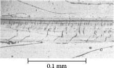
FIGURE 7.11
Wear track on 12–μm-thick tin–nickel electrodeposit having an overplate of 0.43 μm dc-plated cobalt–gold. Diamond rider; 90° conical tip with a radius of 0.1 mm. Single pass at 200 gf. Note the brittle fracture in the deposit. (After M Antler, IEEE Trans Parts, Hybrids, Packaging PHP-9(1): 4–14, 1973 [46].)
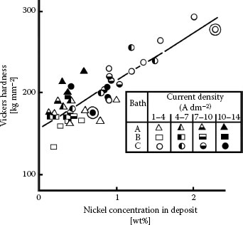
FIGURE 7.12
Variation of hardness of nickel-hardened gold with nickel content, for a wide range of values of electrical current densities during electroplating. (After LG Liljestrand et al., IEEE Trans. Components, Hybrids and Manufacturing Technology CHMT-8: 123–128, 1985 [47].).
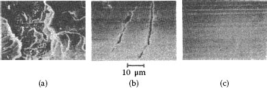
FIGURE 7.13
Two-body abrasion. Worn gold-plated flats from single pass runs at 200 gf with diamond stylus under the same conditions as in Figure 7.11: (a) 3.3 μm hard cobalt–gold on copper; (b) same as (a) with 2.5-μm nickel underplate; (c) 3.3 μm pure soft ductile gold with 2.5-μm nickel underplate on copper. (After M Antler, IEEE Trans Components, Hybrids, and Manufacturing Technol. 4(1): 15–29, 1981 [65].)
7.2.5 Delamination and Subsurface Wear
Delamination is a proposed wear mechanism based on the concept of accumulation of near surface plastic strain. In the model proposed originally [48], delamination wear occurs in repeat-pass sliding when cracks become nucleated below the surface, and finally lead to the loosening of thin sheets of metal that turn into wear debris. Crack nucleation originates in dislocation pile-ups, a short distance below the surface, particularly at a hard second phase in the matrix [48,49,50]. However, unambiguous experimental evidence in support of the basic model has been less than convincing [51,52,53,54,55]. Conclusions that delamination wear was responsible for damage after extended unlubricated repeat-pass sliding of gold-plated contacts [56] were never unequivocally supported by other workers.
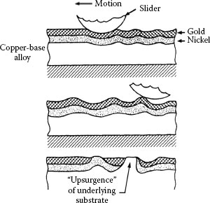
FIGURE 7.14
Steps of the upsurgence mechanism on a gold/nickel/copper surface: upper sketch: generation of pressure on the nickel layer underneath the gold, which buckles the nickel layer and forms surface protuberances above the buckle; middle sketch: preferential wear of the gold occurs as the contact passes repeatedly over the region, leading to local thinning of the gold; bottom sketch: with repeated reciprocating motion, the amount of buckling and preferential wear can increase, leading to localized exposure of nickel and eventual localized exposure of the copper. (After Ref. 58).
In certain systems, sliding can lead to progressive subsurface plastic deformation [57]. This material flow results in a deepening wear groove in the surface and the formation of buckles in the surface layers. Above these buckles, localized surface wear occurs. With repeated cycling, exposure of sublayer material eventually occurs at these sites, with or without a general thinning of the surface layers [58]. The appearance is suggestive of local “upsurgence” of the sublayers, through the surface, as shown schematically in Figure 7.14. This mechanism is affected by load, number of cycles, and the thickness and stiffness of the surface layers. It was also found that with sufficiently thick and stiff layers, the mechanism could be eliminated.
7.2.6 Effect of Underplate and Substrate
In general, hard materials are more wear resistant than soft materials. This property originates in the reduction of real area of contact associated with increased hardness and hence in the smaller probability of material removal from the surface during sliding. Area of true contact is thus a basic determinant of all wear processes. It is obvious, therefore, that when considering layered materials, like noble metal contacts made by electroplating or cladding, increasing underplate and substrate hardness may mitigate wear, particularly where the coatings are thin.
Examples of the beneficial role of a hard nickel underplate in reducing wear in gold electrodeposits are given in Figure 7.15 for adhesive wear and Figure 7.16 for abrasive wear [59]. In Figure 7.15, hemispherically ended solid gold riders with a diameter of 3.2 mm were mated in reciprocal motion to pure and to cobalt–gold-plated flats at a series of loads. The tests were carried out for various numbers of reciprocating passes on 1-cm-long tracks. In Figure 7.16, the rider was a 90° conical diamond having a rounded tip with a radius of 0.1 mm, and individual runs were made for a single pass at a series of loads. Wear was determined by paper electrography. The Wear Index is the ratio of the sum of the lengths of the decorated features in the electrograph (i.e., the lengths of separate wear deposits along the wear track) to the total track length multiplied by 100. It is evident that the nickel underplate, which was the hardest material in all cases, was highly effective in reducing wear rates in the gold.
Figure 7.16 illustrates the advantage of combining a hard substrate, copper–beryllium, with a nickel underplate. The superiority of a cobalt–gold electrodeposit compared to pure gold in adhesive wear is also shown in Figure 7.15, as discussed earlier in connection with junction growth. On the other hand, pure ductile gold on a nickel underplate is superior to cobalt–gold in abrasive wear (Figure 7.16b and d) because it does not degrade by brittle fracture; junction growth plays no role in abrasive wear.
Additional examples of the beneficial value of multilayer coatings were reported in studies with electroplated gold on palladium and electroplated gold on clad Pd70Ag30 alloy [60]. In these cases, the second layers were less noble but harder than gold. The advantage of composites, aside from superior durability, is that they may prove to be lower cost replacements for thick gold electroplates. This development is discussed in Section 7.4.
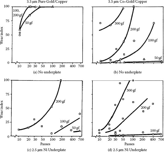
FIGURE 7.15
Electrographic wear indexes from unlubricated adhesive wear runs with 3.3-μm-thick gold electrodeposits: (a), (c) ductile pure gold, with and without 2.5-μm nickel underplate; (b), (d) hard cobalt–gold, with and without 2.5-μm nickel underplate. (After M Antler, MH Drozdowicz, Bell Sys Tech J 58(2):323–349, 1979 [59].)
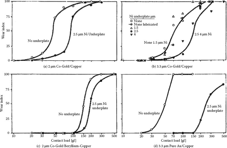
FIGURE 7.16
Electrographic wear indexes from two-body abrasive wear runs with various gold electrodeposits, substrates, and underplates. Conical diamond rider, (a), (c) a hard substrate (beryllium copper) or a hard underplate (nickel) reduce wear of gold plate, and the effects are additive; (b), (d) ductile soft gold plate is superior to hard brittle cobalt–gold plate when nickel underplate is used. Results on specimen without underplate in (d) are poor because gold was non-adherent. (After M Antler, MH Drozdowicz, Bell Si/s Tech J 58(2):323–349,1979 [59].)
Another advantage of hard ductile underplates is that they can reduce the tendency of a brittle overlayer to crack at high contact force. This has been demonstrated with rhodium plate where nickel was found [61] to be a superior underplate to the one that was soft, such as silver. This concept has been used with various three-layer finishes, such as Au–Rh–Ni [62] and Au–Pd–Ni [63]. The system Au–SnNi–Ni would be an interesting finish where the brittleness of SnNi might be circumvented by the hard nickel; SnNi is a desirable underplate because of its inertness [64], which effectively eliminates corrosion in aggressive atmospheres due to pores in the gold.
Yet another advantage of a hard underplate is in sliding friction. Friction is reduced, as well as durability improved, with an increase in sublayer and substrate hardness [65].
Surface roughness has little effect on the wear of unlubricated, identical unplated solid metals [1], except that very smooth clean surfaces may experience excessive junction growth and increased adhesive wear. Actually, in repeat-pass sliding, clean surfaces tend to become roughened as a consequence of transfer and wear to an extent that depends on the material and conditions of the experiment, such as load. In the mild wear regime, particularly with ductile metals, surfaces become burnished during sliding. In lubricated interfaces, surfaces also become increasingly burnished and the lubricant trapped in the valleys between the high spots emerges and continues to protect. When the entire surface has become smooth, lubricant failure and high wear ensue [46].
Gold-plated smooth contacts have been found to wear less than rough surfaces in both adhesive and abrasive wear [66]. This is illustrated in Figures 7.17 and 7.18 where substrates were prepared to three values of roughness and plated with the same mass coverage of gold. One important cause for the increase in wear rate of platings with increasing roughness is that wear tends to occur preferentially on surface high spots [67]. Thus, the gold is lost by wear first from the asperities. With smooth surfaces, wear is less localized than with rough surfaces, and more passes are required to achieve a given level of wear. The wear rate of a clad surface may be affected by the hardness of the mating surface [68].
7.2.7 Electrodeposited Gold: Relationship of Wear to Underplate Hardness
Some studies of the sliding wear of various golds are summarized in reference [57] where it is shown that both high hardness and low ductility are required to minimize the rate of adhesive wear. On the other hand, in Section 7.2.4 it was also indicated that abrasive wear resistance is improved where both hardness and ductility are increased. Subsurface wear resistance (Section 7.2.6) appears also to be increased with increased hardness. Deposit composition, the plating process, topography, underplate-substrate thickness and mechanical properties, and surface cleanliness (lubrication) likewise play a significant role in determining the sliding wear rate of a contact materials system. Our understanding of the interplay of these various factors is incomplete, and much more work is needed to develop a comprehensive quantitative view of contact wear. In this regard, significant investigations of the correlation of wear properties of electroplated gold with deposit composition and plating process are described in [69,70].
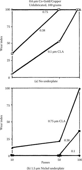
FIGURE 7.17
Unlubricated adhesive wear. Wear indexes from runs on 0.6-μm cobalt–gold-plated copper samples having three degrees of roughness. Solid gold riders. Smooth surfaces gave less wear: (a) no underplate; (b) 1.5 jam nickel underplate. (After M Antler, Insulation/Circuits, 26(1): 15–19, 1980 [66].)
7.2.7.1 Hardener Metal Content
A limited number of investigations have been made to relate the adhesive wear resistance of acid hard gold deposits to cobalt or nickel content [46]. Gold deposits with as little as 0.06% cobalt [71] or as much as 4% cobalt or nickel [72] were found to have acceptable wear behavior. The dependence of hardness on nickel content in nickel-hardened gold has already been shown in Figure 7.12 from the comprehensive investigation by Liljestrand et al. [47]. For the sake of completeness, the corresponding data for cobalt–gold is shown in Figure 7.19 [36]. We note that hardness increases somewhat more rapidly with increasing cobalt than with nickel concentration. Figure 7.19 also shows the decrease in friction coefficient associated with increasing hardness. In recent years, the use of cobalt–gold has fallen into some disfavor due to cost factors and less favorable contact properties than nickel–gold, including the tendency of cobalt in gold to segregate to the surface beyond about 160°C [73]. We shall focus on the wear properties of nickel–gold, since the wear properties of cobalt–gold follow similar trends [65].

FIGURE 7.18
Two-body abrasion. Wear indexes from single-pass runs with diamond stylus on same samples as in Figure 7.17. Wear is inversely related to surface roughness: (a) no underplate; (b) 1.5-μm nickel underplate. (After M Antler, Insulation/Circuits, 26(1): 15–19, 1980 [66].)
The data of Figure 7.12 indicate that hardness increases linearly with nickel content and does not level-off at nickel contents larger than about 0.5 wt% as is the case for cobalt-hardened gold. Figure 7.20a is reproduced and annotated from Antler’s investigations [20,46] and illustrates the durability of 0.1% nickel–gold deposits (H = 150–200 kg mm2) in reciprocating sliding as a function of the thickness of electroplates deposited on oxygen-free, high-conductivity (OFHC) copper flats. The mating rider was 3.18 mm in diameter and was similarly plated. Reciprocation sliding was carried out for 700 passes over a 10-mm track length. The durability of the deposits was determined by the number of passes required for wear off from the flat, for contact loads ranging from 50 gf to 500 gf. The data of Figure 7.20a indicate that durability increased with increasing gold thickness but the rate of increase was not constant. In particular, durability increased sharply as the electroplate thickness increased beyond a critical value. This critical value was found to vary with applied contact load. For example, at a contact load of 100 gf, durability increased sharply for deposit thicknesses larger than about 4 μm. Similarly at contact loads of 200 gf, 300 gf, and 500 gf, there was a rapid increase in durability for gold thicknesses larger than 5 μm, 6 μm, and 12 μm respectively. The sharp durability increase was due to a significant decrease in wear rate after initial running-in. The decrease in wear rate stemmed, in part, from hardening of the gold through deformation and cold-working during running-in. The data of Figure 7.20a also indicate that, for a given electroplate thickness, durability decreased with increasing contact load. This is consistent with the trend predicted by Equation 7.1.
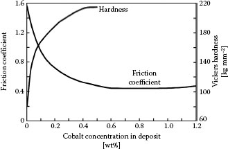
FIGURE 7.19
Variation of hardness of cobalt-hardened gold, with cobalt content. (After M Antler, IEEE Trans Parts Hybrids, Packaging, 10: 177–17, 1974 [36].).
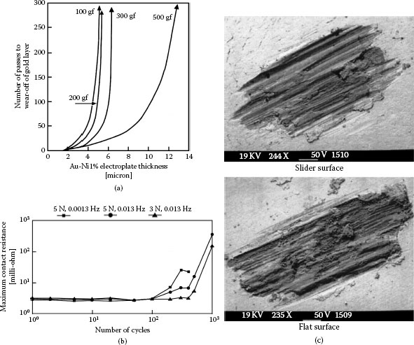
FIGURE 7.20
(a) Dependence of durability of hard gold on electrodeposit thickness (After M Antler, IEEE Trans Parts, Hybrids, Packaging PHP-9(1): 4–14, 1973 [46].), (b) contact resistance versus number of low-frequency cycles at 150°C and contact loads of 3 N and 5 N; 0.2% cobalt–gold on copper alloy (Cu95.5, Si3.0, Sn1.5, Cr0.1) (After CH Leung, A Lee, Proceedings of the IEEE Holm Conference on Electrical Contacts, Philadelphia, 1997, pp 132–137 [74].), (c) SEM micrographs of wear tracks on the slider and the flat surface associated with (b). The light and dark areas consist, respectively, of gold and nickel (or copper) due to larger electron reflectivity of gold.
Over the last decade, the requirement on connectors located under automobile engine hoods to operate reliably at elevated temperatures has led to investigations of wear induced by slow reciprocating displacements due to cyclic thermal expansions and contractions. Such slow reciprocating displacements would occur where the contact load is sufficiently large to mitigate effects due to small high-frequency displacements caused by mechanical vibrations in the engine compartment. Although non-noble metal contacts would be expected to degrade relatively rapidly at elevated temperatures due to increased oxidation rates, it was unclear how gold-plated contacts would perform. All contact degradation mechanisms are thermally activated and become more severe at higher ambient temperature. For gold-plated contacts, these mechanisms include metal softening, possible rapid interdiffusion with substrate materials and diffusion to the surface of hardeners in gold (see Section 7.4), and other possible effects. Figure 7.20b shows the variation in contact resistance of a dimpled surface sliding over a flat, with a number of reciprocating cycles. The mating surfaces consisted of 0.8-μm cobalt–gold on 2-μm nickel on a C65400 copper alloy substrate, and the sliding distance was 300 μm [75]. The work was carried out at 150°C with contact loads of 3 N and 5 N, and frequencies of 0.0013 Hz and 0.013 Hz. Contact resistance increased more rapidly at 5 N than at 3 N. Degradation stemmed from wear through of the electroplate to the underlying underplate and substrate and accumulation of oxidized wear debris. The trend with increased load is consistent with the data of Figure 7.20a. The increased degradation with smaller frequency was attributed to increased time for oxide formation during the reciprocating motion once the protective gold-plating layer had worn through. The SEM micrographs of the contact surfaces in Figure 7.20c show the wear through of the gold electroplates. It was verified that wear led to exposure of the nickel barrier as well as the copper substrate, with subsequent oxidation of the exposed surfaces. It is worth emphasizing that none of the investigations of hardened-gold layers have included a correlation of wear properties with structural or other physical property of the deposits. As indicated earlier, hardener metal content and hardness are by themselves unreliable predictors of the performance of a gold coating in a sliding contact application.
As a class, clad and electrodeposited metals with the same composition are tribologically similar. However, there is a major exception with cobalt and nickel-hardened cyanide gold platings compared to virtually all clad noble metals that have been considered for electronic connector separable contacts. Some plated hard golds are considerably less prone to adhesive wear than corresponding clad materials [76]. This is due to the combination of high hardness and low ductility of electrodeposits, which discourages junction growth and prow formation.
Comparative examples of unlubricated sliding are shown in Figure 7.21. The micrographs compare the wear damage generated between a rider electroplated with cobalt–gold sliding over a flat coated with the same electrodeposited material, with wear produced by sliding the same rider over a clad Au69Ag25Pt6 flat [77]. In the case of the worn electrodeposits shown in Figure 7.21a, sliding remained in the mild regime with relatively small mechanical deformation and small wear debris particles and flakes. In contrast, wear on the clad surface was severe in Figure 7.21b, with a high coefficient of friction. In addition, prows of the clad material were evident on the electroplated-gold rider surface, while the flat clad contact surface was covered with prominent back-transfer prows after repeat traversals. Clearly, the results of these investigations point to the superior wear resistance of the electrodeposited gold coating over the mechanically clad material. The susceptibility of clad material to wear stems largely from weak bonding of the clad to the substrate. Since bond weakness generally occurs locally over a substrate, the wear resistance of a clad surface should vary inversely with the clad area since the wear path over a small clad is short and has a smaller probability of crossing weak bonding regions. This in turn leads to a smaller probability of cladding detachment during sliding. Thus, the use of clad metals should be restricted to the smaller contact component in a connector, in order to minimize the probability of wear due to clad detachment as was verified in practical hardware studies [77].
Guidelines for the use of clad metal contacts in connectors can be summarized as follows:
• Clad metal contacts should not be mated to themselves.
• Clad metals may be mated to a hard gold electroplate or a hard gold-flashed palladium or palladium alloy finish, provided that the clad metal has the smaller swept area.
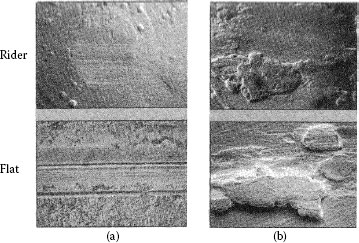
FIGURE 7.21
Worn specimens from unlubricated sliding with electrodeposited cobalt–gold riders and flats of (a) cobalt–gold electrodeposit and (b) clad Au69Ag25Pt6. 100 gf load, 20 cycles. Coefficients of friction at ends of runs: (a) 0.3, (b) 1.2. (After M Antler, Connection Technol 6(3): 29–33, 1990 [77].)
• The plated surface should be smooth, that is, free of surface protuberances and other features which may abrade the cladding.
• It is desirable to use a good boundary contact lubricant.
Tin and tin–lead alloy finishes are widely used for connector contacts. However, these finishes are limited to applications where few, usually only 1 or 2, but generally not over 10 matings, are required in their lifetime. The adhesive wear rate of these materials is estimated to be 100 times greater than that of hard gold plate. These tin-based platings are also easily abraded.
Although pure tin coatings are sometimes specified, their tendency to form whiskers, unless fused, makes tin–lead alloys the preferred finish. Also, tin–lead coatings are more easily soldered at the terminal end of the contact due to their lower melting points than pure tin. Thicknesses of 2.5–5 μm are normally specified, usually on a nickel or copper underplate. Normal loads should be larger than about 1 N for gently curved contacts, because the oxide on these metals must be broken or displaced to achieve a low contact resistance.
The inferior durability of tin and tin–lead alloys is due to low hardness and therefore easy displacement of these materials in sliding applications. Adhesive wear occurs by a pseudo prow formation process, involving metal transfer from the larger to the smaller contact surface involved in sliding; but transferred metal is work softened (observed for 50–50 tin–lead) rather than work hardened. This adhesive wear mechanism has been termed “wedge flow” because the transferred metal on the rider flows in the direction of sliding, as shown in Figure 7.22 [20]. Rider wear soon follows, as in prow formation.
An important aspect of the sliding wear of tin and tin–lead alloys is the effect of intermetallics due to interdiffusion of the tin and the substrate material on the coefficient of friction and contact resistance. Intermetallic materials, such as Cu6Sn5 and Cu3Sn [78,79] for a copper-based underplate or substrate, are hard and characterized by a much larger electrical resistivity than tin. It has been found [80] that there are three stages in wear, as shown in Figures 7.23 and 7.24, described as (i) plowing of the tin—actually wedge flow adhesive wear (Stage 1), (ii) sliding on the intermetallics (Stage II), and (iii) penetration of the intermetallic layers with sliding on the substrate (Stage III). The termination of Stage 1 marks the end of the most useful life of a tin-plated contact. Since the rate of formation of intermetallics is high [78,79], the lifetime of contacts with a tin finish is quite short. In the case of contact surfaces coated with a tin–lead alloy layer, residual lead remains once the tin is consumed in forming intermetallics. Perhaps the sliding of tin and tin–lead should be considered to involve a succession of interfacial materials, which changes the characteristics of the sliding interface as these materials appear in the contact due to wear.
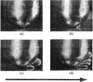
FIGURE 7.22
Wedge-flow mechanism. Solid 50/50 tin–lead alloy sliding on itself, 3.2-mm diameter rider, 2.5-cm diameter circular track, 180 gf: growth and loss of wedge by back-transfer to flat shown. Note metal emerging at rear of rider. A, after 1/4 rev.; B, at 10 revs.; C, 40 revs.; D, 60 revs. Back-transfer solid appears at right in D. Note separation of rider and flat during sliding. Wedge-flow metal originates in flat. Arrow indicates direction of movement of flat. (After M Antler, Wear, 7: 181–204, 1964 [20].).
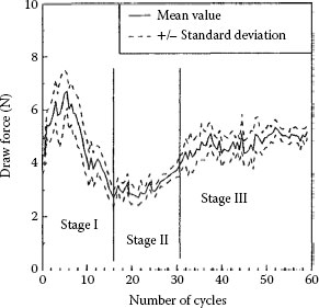
FIGURE 7.23
Variation in draw force during a test sequence and identification of the three stages of wear. Electrodeposited dull tin (10 μm) with a normal force of 1 kgf. (After T Hammam, Proceedings of the 18th International Conference on Electrical Contacts, Chicago, 1996, pp 321–330 [80].)

FIGURE 7.24
Variation in contact resistance during the test sequence shown in Figure 7.23, for electrodeposited dull tin (10 μm) with a normal force of 1 kgf. (After T Hammam, Proceedings of the 18th International Conference on Electrical Contacts, Chicago, 1996, pp 321–330 [80].)
The degradation of tin-based contacts by fretting corrosion has been the focus of much attention, to be discussed in Section 7.3. In recent years, the RoHS legislation (Restrictions of the Use of Certain Hazardous Substances) [81] for the use of lead-free materials has required the removal of lead, including lead from tin alloys used in electronic devices [82]. This has necessitated the development of techniques to minimize whisker formation in tin finishes, such as annealing at temperatures slightly below melting, the use of appropriate underplate structures, and so on [83,84]. Because tin and tin-alloy electroplates are soft and prone to mechanical wear and abrasion, they are limited to applications where relatively few matings (e.g., on the order of 10) are expected in their lifetime. For this reason, connectors designed for frequent matings in service are plated with hard gold which is considerably more resistant to wear than tin. Other wear characteristics of tin and tin-alloy electroplates, and in particular fretting wear, will be described in a detailed description of wear mechanisms.
With the price of gold continuing to climb, silver is increasingly regarded as a relatively low-cost alternative to gold. As will be described later in relation to fretting wear, clean silver contact surfaces have a tendency to stick or weld under a sufficiently large contact load. This stick tendency leads to a high coefficient of friction which in turn leads to poor durability performance and poor fretting properties where sliding displacements are large. In contrast with gold, silver readily forms surface tarnish films when exposed to sulfur-containing and chlorine-containing atmospheric contaminants. Field exposure studies of silver-plated connectors have shown that tarnish films on silver consist primarily of α-silver sulfide (Ag2S) and to a lesser extent silver chloride (AgCl) which is more insulating and potentially harder to displace than the sulfide [85,86,87,88,89,90,91,92,93,94]. These tarnish films are generally semi-conductive at ambient temperatures, mechanically soft, and relatively easily displaced with contact interface wipe at sufficient normal loads. The presence of tarnish films has a significant effect on the wear properties of silver.
Figure 7.25a shows an example of the wear sustained in reciprocating motion by clean/untarnished silver surfaces in a sliding couple consisting of crossed copper rods plated with a 4-μm thick silver coating. The reciprocating displacement frequency was 0.2 Hz at a large contact force of 60 N [95]. As expected for clean silver, the dominant deterioration mechanism in untarnished contacts is adhesive wear and mechanical deformation increases with increasing contact force. Although tarnished silver coatings with a thickness of 2 or 4 μm show no clear evidence of adhesive wear, with the wear track always smooth as illustrated in Figure 7.25b, the amount of mechanical wear depends on the silver coating thickness. For example, the degree of mechanical wear of tarnished silver coatings with a thickness of 19 μm was found to be large and similar to the wear observed for untarnished silver as shown in Figure 7.25a [95], that is, adhesive wear was dominant. The adhesive wear observed with thick tarnished silver stems from breakup and dispersal of the tarnish layers due to the relatively large deformation allowed by the thick metal coating, and ensuing metal flow and exposure of fresh silver leading to sticking and subsequent severe wear. Some measurements have revealed adhesion at contact forces as small as 10 cN on tarnished silver [96]. This is illustrated in Figure 7.26 where the adhesion coefficient α (= adhesion force/contact force) is shown as a function of the sliding distance of hard gold on tarnished solid silver. The larger adhesion with increased sliding distance stems from increased breakup of the tarnish layers, also evidenced by the notable drop in contact resistance. The surface layers of the worn tarnished silver surfaces on copper are often found to consist of a mix of copper oxides, copper sulfide, and silver sulfide [95].
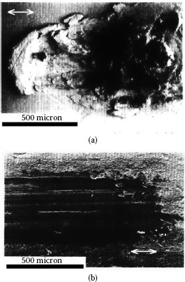
FIGURE 7.25
Surface appearance after 20 reciprocating cycles on a silver coating 4 μm thick at a contact load of 60 N: (a) untarnished surface and (b) tarnished surface. The sliding direction is parallel to the bottom edge of the micrograph. (After A Kassman Rudolphi, S Jacobson, Tribology Inter. 30: 165–175, 1997 [95].)
The data of Figures 7.25 and 7.26 illustrate the following important contact properties of silver coatings:
i. Tarnish films on silver are relatively easily displaceable.
ii The presence of tarnish does not necessarily imply high contact resistance, if sufficient relative interfacial displacement is allowed to disrupt the tarnish layers [97,98]; we will address the issue of tarnish film disruption in greater detail later in description of fretting wear.
iii Relatively thick silver coatings generally lead to lower contact resistance than thin coatings; the superior electrical contact properties of thicker coatings are attributed to easier metal deformation in thick metal coatings and, hence, easier disruption and dispersal of tarnish films on the surfaces of thick silver.
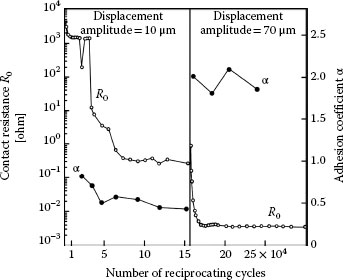
FIGURE 7.26
Solid gold (hardness 200 kg mm-2) sliding on tarnished silver (hardness 80 kg mm-2): contact resistance R0 and adhesion coefficient α as a function of the number of reciprocating cycles. The displacement amplitude was initially 10 μm and was then increased to 70 μm after about 15.4 × 10⁴ cycles. (After H Bresgen, Wear 69: 157–165, 1981 [96]).