
Nature is always hinting at us. It hints over and over again.
And suddenly we take the hint
Comments, Robert Frost
CONTENTS
23.1.1 Fiber Brushes for Power
23.1.2 Diversification of Applications
23.2 Sliding Wear of Multi-Fiber Brushes
23.2.2 Holm-Archard Wear Equation
23.2.5 Plastic and Elastic Contact
23.2.6 Critical or Transition Brush Pressure
23.2.8 Effects of Sliding Speed
23.2.9 Effect of Arcing and Bridge Transfer
23.3 Surface Films, Friction, and Materials Properties
23.4.1 Dependence of Electrical Resistance on Fiber Brush Construction
The term electrical “brushes,” so evidently non-descriptive of the carbon and carbon–metal brushes discussed in Chapters 20 and 21, derives from the bundles of metal wires which “brushed” against the insulating, partly metal-covered electrostatic generator disks of two centuries ago. For more than one hundred years, such painter’s style “brushes” and various modifications thereof in the form of assemblies of metal wires were universally used for sliding electrical contacts. They were displaced by “monolithic” graphite brushes only at the turn of the twentieth century. The compelling reason for the change-over was to decrease wear of both the brushes and the counter-surfaces.
Recent work has demonstrated that “bundled” fiber brushes can provide significant performance advantages over monolithic graphite or composite metal graphite brushes in certain applications. These advantages include higher current density, decreased contact resistance and contact resistance variation (noise), decreased wear debris generation, and improved insensitivity to environmental effects. These advantages are achieved by spreading the force of the electrical contact against its contacting counter-face across relatively lightly loaded contact spots of many independent metal fibers.
This chapter discussing fiber brushes is a natural extension of the discussion in Chapter 22 which discussed single metal fiber brushes. The notion of bundling a number of single fibers into a single brush to carry more current is an obvious one. The contribution made by recent research is to show that multiple contacts allow a significant reduction in brush force per individual fiber while maintaining low contact resistance. However, all the principles discussed in Chapter 22 apply to fiber brushes, and conversely the detailed discussion of wear and friction in Chapter 23 is relevant to the single brushes of Chapter 22.
23.1.1 Fiber Brushes for Power
Much of this fiber brush work was championed by Dr. Kuhlmann-Wilsdorf and her name appears on many of the references used in this chapter. The primary focus of her distinguished career was developing a high current density and low wear bundled fiber brush as shown simply in Figure 23.1 (a) taken from Dr. Kuhlmann-Wilsdorf’s early patent [1]. This illustration shows a bundle of small, metal fibers collected in a holder and impinging on the contacting surface on the fiber tips. Dr. Kuhlmann-Wilsdorf recognized early in her work that one of the keys to successful and optimal operation of the fiber brush was in the control of the local environment of the contacts, and much of the data presented for fiber brush performance has been collected when operating in a controlled atmosphere, for example, moist argon and moist CO2. This has been referred to as vapor phase lubrication [2].
Kuhlmann-Wilsdorf developed a very robust theoretical underpinning for the fiber brushes developed in her laboratory and reference [3] provides a very comprehensive outline of the theory behind multi-fiber electrical brushes. There are several important assumptions made about fiber brushes that overarch this theoretical work. These assumptions are not necessarily appropriate for all fiber brushes, but are inherent in the majority of Kuhlmann-Wilsdorf’s work.
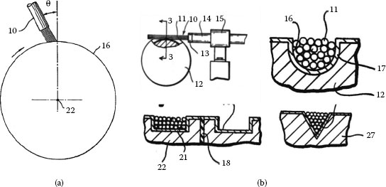
FIGURE 23.1
Fiber Brush Designs (a) This fiber brush illustration is from a 1982 patent of Kuhlmann-Wilsdorf [1]. The drawing shows the basic features of the multi-fiber sliding electrical contact that impinge on the counterface end-on. The slight cant or tilt of the brush allows the brush to be compliant, but does limit the brush to unidirectional rotation. (b) These graphics from the Lewis and Skiles patent of 1983 for a tangential fiber brush design. Unlike the end-on design of (a), this fiber brush design contacts the counterface tangentially allowing bi-directional rotation. The brush force is maintained by the cantilever bending of the fibers, so sufficient brush diameter is required. The brush can contact a flat ring or can be constrained in machined grooves as shown (U-groove, square groove, and V-groove).
1. Fiber brushes are used for transmitting high current and the critical electrical parameters are related to conductivity.
2. Fiber brushes are relatively large bundles of very small (sub 100 μm. diameter), independently-acting fibers with their tips impinging on the counterface. The brush has been described as a “velvet-like mat” made of fibers.
3. The bulk brush length is short and the bulk resistance of the brush is insignificant compared to the contact resistance.
4. The environment and consequentially surface films are well controlled and the resistivity is roughly 10−12 Ω/m2 or equal to 2 molecular layers of water. In most cases this requires a controlled atmosphere to achieve.
5. Fluid lubrication is never used.
6. Normal forces are equally distributed across individual fibers and the fibers are small enough that it is reasonable to assume that there is only one contact spot per fiber.
7. Individual contact spots can be evaluated using the Hertz criteria as elastic or plastic and a critical brush pressure can be determined where the contacts transition from elastic to plastic; low wear occurs under this transition pressure.
There will be a more detailed discussion later of point #4 requiring the strict control of the surface films, but the atmosphere control aspect of this work does highlight the key element of fiber brush design; unlike monolithic brushes (Chapter 20) that contain solid lubricant (usually graphite), metal fiber brushes depend on surface films from external sources for lubrication. As shown by controlled atmosphere tests, this external source of lubricant is primarily the water vapor in the “moist” environment. But these controlled environments serve to limit the contaminants of regular “room air.” The argon or CO2 used in many of the Kuhlmann-Wilsdorf tests ensures that none of the “normal” contaminants of standard industrial environments can play a significant part in the contact zone. These contaminants are one of the primary causes of contact problems in normal metal monofilament or multiple fiber brushes, and it is questionable if the extra light brush force specified in many of these tests would provide insufficient “wiping force” to clean the contacts in an industrial environment. This is especially true of the copper brushes and rings used in many of the tests.
A body of work by Argibay et al. has studied copper on copper at low speed [4], the polarity effect of wear on copper on copper (positive brush wore twice as fast, a phenomenon seen with other brushes to the same degree) [5], beryllium copper brushes on copper rings [2] all in a moist CO2 environment. In addition, studies have been performed on copper with a third sacrificial member (as graphite wiper) to provide surface lubrication without the moist CO2 [6] and a study showed the effect of other “cover gases” than CO2 on beryllium copper brushes on a copper ring [7]. Much of this work by Argibay et al. as has Dr. Kuhlmann-Wilsdorf’s, has been in support of high current sliding contacts for a high power homopolar motor application. The goal has been to provide brushes that can conduct a current density of j = 2000 A in−2 = 3.1 MA m−2 at velocity v = 40 m s−1 with a maximum total loss of LT = 0.25 W A−1 and to be operated in a protective atmosphere of moist CO2. (More information on this homopolar motor application, along with the High Speed Maglev Train Brushes—same high current with lower velocity—can be found in reference [3].)
The assumptions listed earlier are important to understand since the largest body of research work on fiber brushes is centered on one specific approach to fiber brush design, but this is not the only approach. There are successful fiber brush design approaches that contradict every one of these assumptions. The key elements of a fiber brush are: (1) multiple fibers to give multiple contact points, (2) some independence of action (even if limited) of the fibers, and (3) relatively light contact loading from each fiber in contact.
23.1.2 Diversification of Applications
It is unfortunate in many respects that the homopolar motor requirement has been so well funded since it has skewed much fiber brush research toward a very imposing high current requirement, and many of the advantages of the fiber brush technology—low debris generation, modestly high current density, and good reliability—have been pushed to the background. Widespread use of fiber brushes depends on operation in a standard industrial environment with environmental conditions from −50°C to +80°C, 0%–100% RH, sand and dust environments, and typical shock and vibration. Furthermore, they must operate with typical industrial tolerances, provide good reliability and maintainability, and be cost effective. A wind turbine nacelle in Denmark in mid-winter is a far cry from a moist argon lab environment.
Two application notes [8,9] report on an alternative fiber brush design that is used in industrial slip rings, although there is little published research on this approach. Figure 23.1b shows this tangential fiber brush as presented in the patent [10] for the design. The tangential fibers must be longer and larger in diameter than those reported by the Kuhlmann-Wilsdorf and Argibay teams (for structural integrity and contact force generation), and they impinge tangentially rather than on end. This tangential design has been used in medical imaging CT scanner applications (70–180 RPM on a 1.5m diameter, 100 amp, 20M revolution life), radar and wind turbine applications (40–100M revolution life), and military helicopter blade de-icing (harsh environment, high reliability). Figure 23.2 shows an example of one slip ring in a standard industrial slip ring product line used in packaging equipment, robotics, and industrial machinery. This entire product line utilizes tangential fiber brushes.
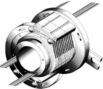
FIGURE 23.2
Illustrates a commericial slip ring product utilizing tangential fiber brushes for both power and signal transfer. This product line is used for a wide range of industrial and defense applications and has been in wide distribution since the late 1980s.
The important point to recognize is that the fiber brush concept of utilizing multiple fibers with lightly loaded contacts has a broad range of potential design approaches. Improving contact life, good maintainability, and high reliability are important design goals for many industrial, medical, and defense applications, and the whole range of lubrication schemes, contact design, and materials can be and should be utilized to approach each application. Sometimes (but definitely not all the time) a fiber brush approach is the best design approach. The generic approach of utilizing a bundle of multiple, lightly-loaded metal fibers to carry current in applications requiring long life and low maintenance has value in a number of important applications.
Almost all of the research on fiber brushes is centered on the advantages of this technology in power transfer requirements. However, instrumentation and control slip rings (see Chapter 22) have incorporated fiber brush technology to advantage primarily for the reduction of contact noise over long life. Fiber brushes are actually a collection or aggregation of monofilament wipers discussed in Chapter 22. In fact some researchers are starting to test single fibers as a method of gaining a better understanding of multi-fiber brushes [7] and “remove some of the complexities typically encountered in macroscopic scale experiments with multi-fiber metal brushes.” This particular study is also interesting in that it evaluates the wear of the brush impinging on the ring tangentially rather that end on. The advantage of using a large number of metal brushes to carry current is obvious, but there are also advantages for transmitting signals. Multiple contact points can improve contact noise performance. Since contact noise is typically improved by the addition of multiple contact points, an entire fiber bundle can be useful in providing redundant signal paths and in reducing noise. It is important to understand that there is still a brush/pressure trade-off. If the contact pressure per fiber is insufficient to penetrate the surface film, having multiple contacts will still result in high noise.
Fiber brushes (tangential) have been used successfully in vacuum applications where surface films are not an issue and the very light contact force per fiber minimizes wear. The absence of adventitious lubrication in vacuum environments (especially moisture) makes these applications especially challenging for sliding contacts. Fiber brushes (tangential) have also been used in slip ring applications requiring long life and low wear debris generation. Two specific cases are radar antennae and wind turbine pitch control systems. These are both applications that require long life (frequently 50–100 million total revolutions or ~ 2.5-5.0 × 10⁷ m of equivalent linear travel), low maintenance intervals, and both efficient power and low noise signal transfer.
This chapter will first address fiber brush contacts from a wear perspective to show wear advantages of the technology in certain environments or applications. Next, we consider the contact films that are critical to the successful operation of the fiber brushes since these brushes do not carry their own lubrication along like the more common metal graphite brushes. Electrical resistance is then considered since this electrical performance parameter is to most critical for successful implementation of fiber brushes. Finally we will consider some unique dynamic considerations for implementation of fiber brushes.
23.2 Sliding Wear of Multi-Fiber Brushes
Chapters 7, 20, and 22 provide an overview of sliding contact of common electrical contact materials. The discussion in this chapter will build on the ideas presented in these chapters to discuss the performance of multi-fiber groups of contacts impinging on a counterface. The load-bearing contact between a brush and its counterface occurs only at a number, n, of isolated areas called contact spots, or to the extent that they conduct current, called a-spots. In old-fashioned metal wire brushes, contact force was typically high to ensure good contact in the presence of contaminating films. This high contact force led to high wear. New design strategies with fiber brushes have significantly improved wear and electrical performance by “dialing back” on the contact force. Improved knowledge of contaminating films is being used to address the surface film problem that high force addressed previously.
Since the entire premise of utilizing multi-fiber brushes is based on the ability to control wear, the subject of sliding wear of electrical contact materials is worth exploring. The assumptions we make about the mechanical properties of potential contact materials are appropriate to highlight:
1. The materials that meet the conductivity and resistance to corrosion/filming requirements for sliding electrical contacts are the noble metals and their alloys (in the order of their nobility—Au, Pt, Ir, Pd, Os, Ag, Rh, Ru, and Cu*).
2. Most of these contact materials are ductile and the most common ones (Au, Ag, Pt, Pd, and Cu) are extremely so. They are sometimes alloyed to control hardness (and stiffness) which effects ductility, but in general these materials can be considered ductile.
3. These materials are relatively corrosion resistant, at least Au through Ag. Corrosion products have a significant effect on the free surface energy of wear particles and surfaces.
There are three common materials used for fiber brushes and each has its place in contact design. All of these materials can be used with or without lubricants depending on the environment and performance requirements.
1. Gold and gold alloys: Gold is used in applications that call for low contact resistance and resistance variation and environmental contamination cannot be controlled. Gold will allow low brush force with a lower risk of high resistance owing to surface contamination. Typically a hard gold counter surface is used, but other less noble surfaces can be used and the gold from the brush will transfer onto the counterface forming a gold wear track. This is clearly an expensive option for large diameters.
2. Copper and copper alloys: Copper is a good material for contacts owing to its high conductivity. As discussed above it is not one of the noble metals and corrosion products can cause high contact resistance. In the unalloyed state it is also quite soft and alloys are used to increase the hardness (BeCu is the most common alloy). To use copper and copper alloys the local environment must be controlled to permit low brush force without excessive insulating film development. The counterface is typically copper, but more noble materials can be used to control insulating film development.
3. Silver and silver alloys: Silver has the advantage of noble metal properties, high conductivity, and lower cost than gold. Counterfaces of gold, silver, or copper can be used depending on the electrical and wear properties desired. Typically silver alloys are used to alloy increased hardness without too great a loss in conductivity.
Rabinowicz [11] discusses four types of wear: (1) adhesive, (2) abrasive, (3) corrosive, and (4) surface fatigue, and maintains that adhesive wear is the most common and difficult to avoid (see also Chapter 7). Blau [12] (pp. 58–59) compares wear classification schemes of 8 different researchers and Rabinowicz’s list is common to most and certainly the most relevant to electrical contacts. It is very important to realize that these lists are research constructs to help explain physical phenomena, and nature is not as helpful in actual wear processes. Trying to identify wear modes is a tricky business.
Adhesive wear occurs through the formation of small wear particles generated by adhesion between asperities on the surfaces. The particles are generally produced from the softer side. Greater understanding of these adhesive connections has come from the advent of the atomic force microscope (AFM) and the surface forces apparatus (SFA) and the ability to study individual sliding junctions at the molecular level with these instruments. The reader is pointed to these works for a discussion of this fascinating topic of adhesive and surface dynamics at the molecular level [13,14,15,16,17,18,19,20]. Of particular interest to the area of sliding contacts is the discussion [13] of a contact discontinuity process called “jump in” in ductile materials (most electrical contact materials), wherein at a close proximity (nm), voids in a contact area become unstable and suddenly collapse and “coalesce” to become cold welded. This cold welding process has been discussed for years by tribologists, and the molecular perspective of these “nanotribologists” brought to this phenomenon has filled in a number of holes in the understanding of this process.
Bonds formed in sliding must in turn be broken as sliding continues. Adams, in his review of the mechanics of adhesion [21,22], reviews the characteristics of ductile separation of the adhesive bond:
1. The contact radius decreases slowly before a sudden separation (typically at a significant reduction of the maximum contact radius);
2. The asperity if stretched significantly during separation owing to plastic deformation;
3. A neck is sometimes formed during ductile separation.
Most sliding electrical contact materials are ductile in nature, although significant cold work in the contact region can reduce the ductility. In the case of alternative brittle separation (as is the case with Ru or heavily cold-worked Au or Cu), there is little or no plastic deformation on unloading.
23.2.2 Holm-Archard Wear Equation
Holm proposed a linear relationship for adhesive wear [23,24] that related the wear volume (V) to through a dimensionless wear parameter KHA, the length of sliding path (Ls), force (P) and hardness (H):
(23.1) |
KHA is the probability that adhesive junctions when broken will form a wear particle. For a porous material and metal wire bundles, in which only the “packing fraction” f is occupied by solid and (1 – f) is fraction of voids, this relationship may also be written in terms of dimensionless wear rate as
(23.2) |
with Δℓ the worn-away layer thickness, a is the average radius of the contact spot, and p = P/πna2,and is the macroscopic normal pressure between the two sides. This relationship between wear and normal pressure is now commonly referred to as “Archard’s law” [25], but should more properly be called the Holm–Archard wear law.
The problem is that the relationship between adhesive wear and force is much more complicated than can be expressed in a linear relationship. To quote Rabinowicz on the accuracy of the Holm-Archard law, “Many investigators have found that this equation is not always perfectly obeyed, but in almost all cases it represents the experimental data reasonably well.” This is a “technical” way to say that wear data are usually ill-behaved primarily because the variables are so hard to control. In a study of three-dimensional fractal surfaces in normal contact, Yin and Komvopoulos [26] conclude that “the adhesive wear coefficient of rough surfaces in normal contact can vary by an order of magnitude depending on the material properties, surface compatibility, and environmental (lubrication) conditions.”
In the case of adhesive wear, the first stage is simply the adhesive transfer of a wear particle from one surface to the other, and in the case of sliding electrical contacts, this transfer is almost always intended to be from the counterface to the brush. It is the next phase that is most important for brush design. In the case of a well-designed metal wire on metal counter-face contact system, this wear material is transferred back and forth from ring to brush forming an equilibrium condition for a long life system. This process is identified with ductile materials under light loads. The reader is referred to Chapters 7 and 22 for additional details of the adhesive wear process. Assisting in the long terms stability of a well-designed system is gradual wearing-in of the counterface surface eliminating the highest asperities.
In these equilibrium wear states, some wear particles are created as they “escape” from the system, but they tend to be agglomerations of very small wear particles (see Rabinowicz [11] pp. 142 ff for a detailed discussion of wear particle generation). Figure 23.3 shows a very good example of this transfer process in a noble metal fiber brush application in a standard atmosphere. The layered wear debris build-up on a single fiber with incipient wear particle generation is almost identical to those particles and wear patterns shown in Chapters 7 and 22, as it should be since it is essentially the same process.
It is clear in the derivation of the adhesive wear relationship of Equation 23.2 [25] that the adhesive wear refers to the transfer of the particles from the wearing surface to the rider. In the case of very ductile materials, the formation of a pad of wear material that is not really lost from the wear surface confuses both the understanding and the measurement of the wear volume. Yin et al. also assume that an asperity that is truncated from the counterface is directly transformed into a wear particle, and these analyses were performed on relatively brittle materials [26].
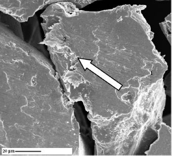
FIGURE 23.3
Photomicrograph from [42] showing transferred material on the fiber tip in a laminar construction. Wear particles can be seen about to separate from the brush. The arrow points in the direction of sliding. (From L. Brown, D. Kuhlmann-Wilsdorf, and W. Jesser, Components and Packaging Technologies, IEEE Transactions on, vol. 31, pp. 485–494, 2008 [42].)
In this “low wear” state the wear process that actually transfers particles out of the wear region primarily occurs as shearing of interlocked asperities. Chang et al. describe the process observed in unlubricated copper multi-fiber brush sliding on a copper counterface as follows: wear particles are sheared off, principally from the softer side, where plastic contact spots momentarily “adhere” after traversing m* times their own diameter on average [27]. This is a mechanical “interlocking” that develops as part of the adhesive transfer process. Chang observed that the average wear particle volume was in the order of 6a3pl
(23.3) |
or Equation 23.2 with the constant KHA in the Holm–Archard law equal to 1/m*. The effect of simultaneous current flow was to mildly increase the average wear chip size, presumably because of a decrease of hardness (H) through Joule heating.
This adhesion/abrasion process of ductile materials leads to some confusion in the study of sliding electrical contacts, since material transfer is occurring in an adhesive manner, but the final wear debris generation in the equilibrium condition is occurring as part of an abrasive process. If we look again at Figure 23.3, for example, we see laminar, heavily work-hardened material built up on the fiber tip. This is ring material that has become adhered to the brush either through an adhesive process or an asperity shearing and smearing process (or a combination of both). Wear particles that are expelled from the contact area are generated by abrading owing to asperity interlocking or just general instability of the wear particle or lack of sufficient adhesive force. Particles can be observed in Figure 23.3 ready to break off the edge of the wear pad.
Wear particles observed in gold-on-gold contacts in this wear mode are very small, dark in color, and much harder than either contact material (i.e., heavily cold-worked, very small, abraded gold particles). Wear measurements inevitably measure the particle generation rather than the transfer rate, and without a very long term test with the ability to capture average wear rates it is difficult to understand the wear of prow-forming, ductile materials.
Accelerated wear situations do not settle into this equilibrium, low wear condition. Rabinowicz argues that this is primarily the result of wear particles whose elastic energy exceeds the surface energy required to adhere to the wiper (internal elastic energy > surface energy or the condition of a prow-forming material). Obviously, the high wear condition can be caused by gross plowing of abrasive asperities or third party particles, but the most frequent cause of high wear with sliding electrical contacts is adhesion. The difference between contact adhesion that reaches a “low wear equilibrium” and adhesion that produces high wear can be frustratingly subtle.
Figure 23.4a is a well-known curve that shows the wear transition effect (wear particle generation) as a function of brush force for unlubricated gold-on-gold. This curve shows that below 5 grams (0.05N) the wear coefficient is low, and it is easy to get the perception (owing to the log x axis) that there is a sharp increase after 5 grams. Figure 23.4b shows the same data plotted without the log scale on the x axis and actually shows a reasonable linear fit. The important point is not the exact relationship of the wear coefficient to force, but rather that this increase is in the wear coefficient that Holm-Archard specifies as a constant adhesion transfer probability.
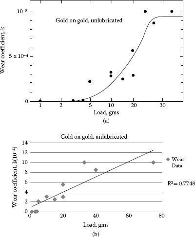
FIGURE 23.4
(a) A well-known curve redrawn from [11] p. 160. The log scale on the x-axis makes the data look more dramatic than it is. The curve redrawn on a linear scale shows a reasonably good fit for a linear trend. The (a) plot does give extreme emphasis to the three low wear points and low wear is notoriously difficult to measure consistently. Rabinowicz’s conclusion that gold has a very low wear coefficient below 5 grams is still reasonable and widely accepted. (Redrawn from E. Rabinowicz, Friction and Wear of Materials. New York: John Wiley & Sons, 1965 [11].)
23.2.5 Plastic and Elastic Contact
Molecular dynamics modeling has shown that in the case of nano-contacts of Au with a radius of curvature of 3 nm [28] there are three different separation modes for asperities joined by adhesion. These three modes in the order of increasing adhesive energy are: (1) elastic separation, (2) plastic interface separation, and (3) plastic non-interface separation (accompanied by material transfer). Adams points out [22] that these results are qualitatively similar to the continuum models of other researchers [29,30,31]. It is clear that if asperity contact can be controlled to minimize plastic non-interface separation, wear can be minimized.
The modeling of elastic-plastic contacts has received significant attention by recent researchers, and clear differentiation between elastic and plastic contact regimes is only as accurate as the assumptions made about the size and distribution of the asperities. This modeling research is well described by Jackson and Green [32] and is divided into statistics-based, fractal-based and FFT or spatial frequency–based modeling. Ciavarella et al. [33] also summarize these various surface descriptions and compare many of these models to numerical experiments. It is important to note that there is reasonable correlation between all these multi-asperity contact models of elastic-plastic contact in most of the range of contact pressure [34].
Yin and Komvopoulos [35] develop an adhesive wear model of fractal surfaces that is very instructive for our purposes and their conclusions are useful:
1. Plastic deformation at asperity contacts depends on the elastic-plastic material properties, topography (roughness), and work of adhesion (material compatibility and contact environment or lubrication condition of the contacting surfaces).
2. The plastic contact area is a very small part (<1–2%) of the total contact area, revealing the dominance of elastic deformation at the asperity level over a wide range of the global interference (i.e., normal force).
3. The wear rate increases monotonically with the global interference, whereas the wear coefficient decreases rapidly to a steady state, showing a wear dependence on normal load.
4. Both the wear rate and the wear coefficient decrease with the interfacial adhesion and increase with the roughness of the contacting surfaces.
5. The adhesive wear coefficient may vary significantly depending on the material properties, surface roughness, and work of adhesion that depends on surface energies of the contacting surfaces and interfacial adhesion controlled by the material compatibility and contact environment.
These conclusions tell a much different story than told by the linear Holm-Archard Equation 23.2. As put succinctly in a review article in Nature on the nonlinear nature of friction [20], “The multitude of asperities on two shearing surfaces are constantly coming into and out of contact, where the local pressure between them can fluctuate between ~ 1Pa (10−5 atmospheres of pressure) and GPa (104 atmospheres) within microseconds. These are extreme conditions that cannot always be treated by simple ‘linear’ theories.”
In fact, the story on sliding contacts is coming into better focus from the aforementioned improved modeling on the macroscale and with the advent of the atomic force microscope (AFM) and the surface forces apparatus (SFA) and their ability to study individual sliding junctions at the molecular level. In the case of the sliding of two surfaces across each other where electrical contact is required, there is both reversible (elastic) deformation and irreversible (plastic or viscoelastic) deformation. The wear and friction properties of these surfaces depend on the adhesive properties of the contacting surfaces or the work of adhesion and these adhesive properties can be and often are non-linear. Quite often, friction and wear cannot be predicted strictly by force, hardness, and a constant.
Fiber brushes are able to maintain a low wear regime by utilizing multiple independent contact points with each contact point very lightly loaded. Kuhlmann-Wilsdorf et al. [3,36,37,38] define a critical brush force (transition from low wear to high wear) in terms of elastic and plastic asperity deformation, i.e., there is some critical brush pressure at which elastic contact transitions to plastic contact at each asperity. The argument is then made that this critical force (or pressure) is the transition from low wear to high wear. An equation is derived calculating this critical brush pressure [36,38]. This seems to be a reasonable approach for defining a design pressure for fiber brushes, but let’s understand the assumptions of this approach better.
23.2.6 Critical or Transition Brush Pressure
If we turn our attention to the critical force or pressure that defines the transition between low and high wear, we do see repeated reference to a critical pressure. Depending on the model being used, there are a variety of expressions for this critical pressure. Wilson, et al. [39] express the critical force in terms of spatial frequency; Yan and Komvopoulos [40] express it in terms of fractal parameters. This critical force is typically normalized to the force required to achieve 100% contact in the apparent area. In light of the evidence that there is a critical brush force that represents the knee of a brush force-wear rate curve around the elastic/plastic transition pressure, it does seem desirable to find a simple equation that helps determine this critical force is for fiber brushes.
In the case of fiber brushes, the number of contact spots is high, each fiber (i.e., contact spot) is capable of acting independently (at least that is our assumption) and the applied force per fiber is as low as possible and still has good electrical contact. Kuhlmann-Wilsdorf [3,41] makes the simplifying assumptions of: (1) a fiber bundle that produces distributed multiple semi-circular “Hertzian” asperities that have a radius of curvature, rc, approximately the same radius as the individual fibers, (2) a perfectly flat and rigid counterface, and (3) each of these asperities can be loaded up to, but not exceeding its elastic limit. A total critical or safe brush pressure is then defined in terms of this individual fiber elastic limit.
Each of these contact spots has the radius, ael, of
(23.4a) |
The average local pressure per elastic contact spot pelb
pelb=Pnπa3el, or by re-arranging |
(23.4b) |
(23.4c) |
To a useful first approximation we may write H ≈ 0.004E as shown by Table 24.1C. We may also define n* as the number density of contact spots at the interface; therefore substituting (23.4c) into (23.4a) we can derive the average local pressure per elastic contact spot in terms of total brush force (P), elastic modulus (E) or alternatively in terms of hardness (H) and brush pressure (pb=PA)
pelc=P1/3E2/3/(n1/3π1.12r2/3c)≈0.26(pBE2/n*r2c)1/3≈10.44(pBH2/n*r2c)1/3 |
(23.5) |
The critical force at the transition between elastic and plastic contact spots, Ptrans, is found by equating the average pressure of the Hertzian, elastic contact spot with H, that is,
(23.6) |
which yields
Ptrans=π31.16(H3/E2)n r2c≈9×10⁻⁴ Hnr2c |
(23.7) |
and for the macroscopic pressure at transition, ptrans and rc = fiber radius,
ptrans≈9×10⁻⁴ Hn*r2c≈3.5×10⁻⁶ En*r2c |
(23.8) |
Figure 23.5a from [36,38] shows the results of tests of silver-clad copper fibers on a copper interface (slip ring) in a moist CO2 environment and data from tests performed with silver brushes on a gold-plated commutator [42] in a standard laboratory environment. The data show the wear vs. brush pressure relationship. The calculation of ptrans in this graph is based on two basic assumptions mentioned earlier: (1) each of the fibers acts independently and the force is equally distributed among the fibers, and (2) the radius of curvature of the contact spot equals the fiber diameter. The researchers report a power law relationship between wear (W) and normalized brush pressure (β, normalized to the transition pressure of Equation 23.8) proportional to β4.6. These data suggest that under this very particular set of environmental conditions, by placing a reasonable factor of safety of two on the critical brush pressure (i.e., normalized force is 0.5), a dimensionless wear rate of ~ 10−11 can be achieved on the slip ring and about 2 × 10⁻¹¹ on the commutator. The paper’s authors explain this difference as variation between a slip ring and commutator.
Figure 23.5b puts a different spin on the same data. There is an excellent linear fit on the slip ring data suggesting that in the narrow range of brush pressures below the transition pressure the wear rate follows the Holm-Archard law. The linear fit is not as good on the commutator data, but the best fit does match the slope of the slip ring data suggesting a similar wear coefficient. It is understandable that the data scatter on a commutator with slots would be greater than a slip ring. These data suggest that the wear coefficient of copper-on-copper fiber brush/slip ring pair in a controlled moist CO2 environment is very similar to the silver-on-gold commutator in a laboratory environment after an initial run period. This correlation in slope is likely owing to similar material properties, but more importantly, similar film properties (controlled atmosphere vs. noble metal).
To put into perspective the values of Δℓ/Ls in the 10−9 to 10−11 range for 12Ptrans
One of the most important advantages to fiber brushes is low quantity of wear debris generation compared to metal graphite brushes. As metal graphite brushes wear, significant amounts of conductive debris are generated as the graphite wears “sacrificially.” Fiber brushes generate less debris as they wear which provides reliability and maintainability advantage as well as the potential for improved life. It is important to operate any fiber brush design at the minimum operating pressure that will provide adequate electrical performance. Equation 23.8 provides a reasonable starting point for brush force calculations and likely represents the minimum force for adequate electrical performance since the assumption is a minimum surface film thickness. As discussed later, operation of fiber brushes in standard industrial atmospheres might require lubrication or allowance for additional surface films which might require higher brush pressures. Tests will be required to ensure that wear rates are acceptable.
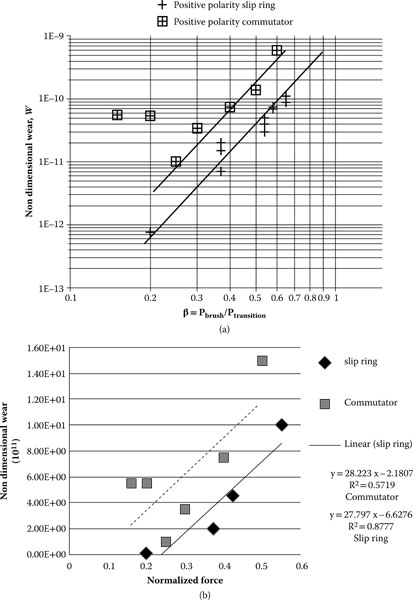
FIGURE 23.5
(a) Dimensionless wear rates for positive polarity brushes on a slip ring (+) and commutators □. The two trend lines show the wear rate dependence on brush force plotted on a log-log scale. Researchers report a power relationship of β4.6 (b) Same data as (a) with a linear fit. Good fit of slip ring but less correlation for commutator. Greater scatter of wear data resulting from the commutator slots would be expected. (Data from L. Brown, D. Kuhlmann-Wilsdorf, and W. Jesser, Components and Packaging Technologies, IEEE Transactions on, vol. 31, pp. 485–494, 2008 [42].)
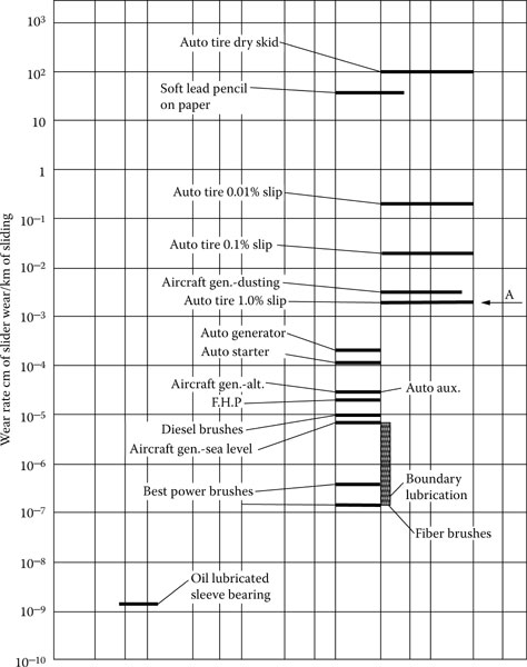
FIGURE 23.6
Dimensionless wear rates and friction coefficients of a wide range of monolithic brushes plus several other sliding situations owing to Shobert (Figure 6.1 of Ref. [42]), into which the data of Figure 23.5 have been added as “fiber brushes.”
23.2.8 Effects of Sliding Speed
The transient local temperature peaks during electrical contact sliding as a result of friction are called the “flash temperature” [44], and this transient temperature has been recognized as a contributing cause to wear and deterioration of sliding electrical contacts. The temperature rise is attributable to both frictional heating and Joule heating. The actual asperity flash temperature can be an order of magnitude higher than the temperature in the apparent contact area [45]. The equations for computing the average temperature rise at contact spots above ambient are quite involved, especially when both friction and Joule heat must be considered. This is so even though the heating effects owing to the two contributions are simply additive, and to a good approximation Joule heating is independent of speed and friction heat is independent of current flow. The complexities arise because the rate of frictional heat generation increases with sliding speed while the rate of heat dissipation also increases as a result of an increased convection coefficient. The Joule heating effects of electrical contacts are discussed in detail in Chapter 1, so we will deal with the heating effect caused by sliding.
The pertinent mathematical theory of flash temperatures at contact spots was developed by Jaeger [46,47] and Blok [48]. Since that time notable research work on this subject has been done on flash temperatures of rubbing surfaces by Archard [49], Burton [50], and Barber [51] and, specifically, electrical contacts by Holm [24] and Rabinowicz [52]. Kalin presents a very thorough comparison of different theoretical models for flash temperature [53] and concludes that large discrepancies in the results can be obtained using any calculation technique because, typically contact conditions vary greatly in both time and place and all involve some very tenuous simplifying assumptions.
Research has been done using sophisticated mathematical models to simulate sliding frictional heating to address these problems. Vick and Furey [54], in a basic theoretical study on the temperature rise in sliding contacts with multiple contacts, found several important trends. Several of these points demonstrate why fiber brushes can be effective in ameliorating frictional heating:
1. Downstream contacts are hotter than upstream contacts owing to the convective effect.
2. The temperature rise decreases as the number of contacts increases.
3. The temperature rise decreases as the spacing between the contacts increases.
4. The shape of the contacts has only a small influence, except for very slender or long contacts.
5. Temperatures can be significantly overestimated using a single contact model.
Kuhlmann-Wilsdorf et al. [3,41,55,56,57,58,59,60] have developed a series of equations for using flash temperature calculations to predict speed and current density performance. These equations are included in Appendix A.1 for applications that closely follow the design constraints imposed by this design: negligible bulk brush resistance, optimum film formation (i.e., lowest possible film resistivity owing to controlled environment), and very small fibers, low packing factor). But it is truly hard to determine acceptable design criteria for flash temperatures, so the advantage of performing these calculations is unclear. Kuhlmann-Wilsdorf suggests that 200°C is the maximum acceptable flash temperature owing to damage to the lubricating moisture layer, but many researchers suggest that the melting point of the contact metal is the maximum. The reader is referred to the very complete derivations and discussions in the references above for more information. Beware however, Kalin [53], in his thorough review and comparisons of various flash temperature models, concludes that simplified, ready-to-use flash temperature calculations can be rather speculative and can lead to very different results on the basis of the model and input parameters.
As always, it is important to subject calculated values to the “engineering reasonableness” filter. Figure 23.7 shows the critical velocity of the Kuhlmann-Wilsdorf brush design using the assumptions inherent in the design and operational characteristics. If we pick one data point, β = 0.5 (safety factor of 2), fiber diameter of 50 Mm, the chart suggests a critical velocity of 400 m/s in a moist CO2 environment which is faster than the speed of sound. A 1.5 m diameter CT slip ring spinning at 240 RPM (4 rev/sec, 19 m/s) is a fast surface speed and challenges any brush technology. It is difficult to imagine brushes operating at 21 times that speed with enough force to maintain good electrical contact surviving more than a few minutes. Kuhlmann-Wilsdorf acknowledges the unrealistic appearance of these values [3] p. 370, but points to data that supports the values [41]. In fact, the data from these rail gun experiments referred to suggests a catastrophic contact failure.
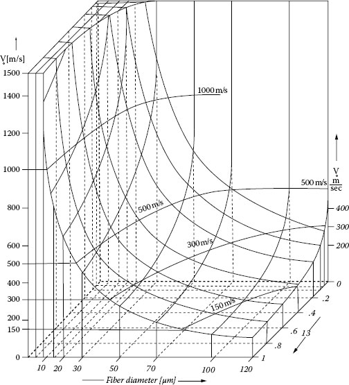
FIGURE 23.7
Critical velocities (v*o=κCu/r=1.14×10−4/r [mks]
Most researchers, starting with Blok and Jaeger, use the Peclet, Pe, number to differentiate between low and high speed sliding contact. The Pe number is defined as Vd/4*χ, where V = velocity, d = contact diameter, and χ = thermal diffusivity. Researchers generally agree with Archard’s summary of previous work [49] that contacts with Pe values of <0.1 are low speed and Pe values of >5.0 are high speed and >10 is very high speed. In the case of 50 μm. fiber brush design discussed above, the Pe number for 400 m/s for each fiber of the brush is 44. At issue is not necessarily Kuhlmann-Wilsdorf’s method of estimating flash temperature, but the assumption that the very low brush forces typically specified by her designs will yield acceptable results with such high velocities (Figure 23.7).
Bansal, et al. have developed a very serviceable set of design curves for temperature rise in sliding elliptical contacts [61] using a rigorous regression based methodology [62,63]. Bansal finds that the Kuhlmann-Wilsdorf [44,55,56] analysis under-predicts the contact temperature (both average and maximum) by 15–40% for most practical cases. In cases where the brush design does not satisfy the design constraints of Kuhlmann-Wilsdorf, it would be better to use the more general and versatile design guidelines developed by Bansal et al. [61,63] to determine the maximum (flash) temperature and average temperature in the apparent contact area as a result of friction. These design curves have been developed to allow maximum variability for most design parameters.
Bansal et al. do report in their study of flash temperature models [63] that two very straightforward heuristic equations (one for plastic and one for elastic contact) developed by Tian and Kennedy [64] give very good correlation with Bansal’s detailed models. These equations provide a very simple method for evaluating sliding electrical contacts for flash temperatures and related equations are presented for evaluation of average temperature rise in the contact zone.
Chen et al. [65] report on the development of a three dimensional thermo-elasto-plastic contact model on the basis of models derived in Ref. [66] and the algorithm presented in Ref. [67]. This model includes the mechanical, electrical, and thermal response at the sliding interface for both Joule and frictional heating. The analysis reveals a strong influence of transient heat transfer on plastic strain because of the dependence of plasticity on loading history; plastic strain is greater when predicted by the transient model. And changes in Joule loading has a much more pronounced influence on the time required for the inception of melting than does either normal load or friction coefficient. The value of steady state flash temperature calculations is questionable.
In some instances, fiber brushes do not have the thermal mass typical of a monolithic, metal graphite brush, so more care must be exercised to prevent bulk heating of the fiber bundle from I2R losses as well as from frictional heating at higher speeds. Additional consideration must be given to the I2R losses in the brush itself, as well as in the contact region. Once the thermal loads are established, the long term thermal stability of the system becomes a heat transfer problem. Experience has shown that care must be taken to provide an adequate heat sink at the brush end as well as the ring end of the contact to ensure heat can flow away from the brush. Contact performance is most effective in power transfer if both the brush and the ring transfer heat away from the contact region, so care must be exercised in the thermal design of the assembly. Extreme care must be exercised to ensure that a sharp heat gradient is established to pull heat away from the contact area.
23.2.9 Effect of Arcing and Bridge Transfer
It should also be noted that wear rates for power brushes of all types are typically about two times higher for positive polarity brushes than negative polarity brushes. Chapter 9 discusses the contact physics behind the tendency for material to transfer from the positive brush to the counterface when contact is broken for closely spaced contacts. The Chapter 9 discussion is centered on the macro-effect on electrical switching devices, but the same physics is in play at the asperity level. As contact is made and broken at the asperity level and as all the factors of energy balance at the contact surface come into play, there is a bias toward material loss at the positive brush that does not exist at the negative brush. Repeated field experience and laboratory tests with metal composite brushes as well as metal fiber brushes show that a 2 × factor is typically demonstrated. Figure 4 of [42] illustrates this accelerated wear on positive brushes in a fiber brush test. In extreme cases microarcs can be observed causing extreme wear which normally leads to catastrophic failure. This condition is generally caused by intermittent full separation of the contacts owing to vibration or excessive particulate debris.
23.3 Surface Films, Friction, and Materials Properties
As in the case with all sliding electrical contacts, the films formed at the contact interface are critical for both the friction and wear characteristics, as well as the electrical performance. There are three primary issues to address: (1) these films can cause high film electrical resistance, (2) the lack of films can cause high wear, and (3) the films and their variation can cause friction perturbations that result in dynamic contact resistance problems.
Clean metal surfaces have very high surface energies, so they readily uptake gases from the environment [68] forming adsorbed films on the surface of the metal surface. The behavior of these molecularly thin films and their effect on friction and wear has been thoroughly reviewed by Israelachvili et al. [18], Homola et al. [69], and Gee et al. [15]. This research was summarized by Bhushan et al. [14] in a very useful review article in Nature in 1995. Persson and Tosatti [70] have collected a large number of useful articles on the subject of the effect of thin films on interfacial friction and wear during sliding. It is fair to say that sliding electrical contacts work in the boundary lubrication regime, and nanotribology studies listed above and the boundary lubrication studies in [71,72,73,74] have significantly contributed to the understanding of the impact of these surface films. This research has been primarily focused on the effect of the films on the mechanics of sliding, and we have to turn to Holm [24,75], Greenwood [76], and subsequent work [77,78,79,80,81,82,83,84] to understand the effect on electrical contact. A more thorough review of these films is contained in Chapter 22.
One of the most prevalent of these environmental “contaminants” is water vapor and the presence of water molecules as a part of the film is inevitable except in a few unusual environments (a hard vacuum for example). On average, these films are much thicker than one or two monolayers. In humid conditions they make surfaces seem “sticky” and eventually, at the dew point, they increase to macroscopic sizes, i.e., give rise to sweating and dew formation. Adsorbed moisture films are very persistent indeed. They are present even in desert conditions, and the last monolayer of moisture desorbs from almost any surface only in a good vacuum (smaller than fractions of a mbar or a few Pa, whence the problem with graphitic brushes in space) or on heating to about 200°C.
In spite of the discussed wide variations of moisture film thickness, the measured film resistivity of “clean” metal fiber brushes is typically near ρF ≈ 10−12 Ω m2, corresponding to a tunneling film thickness of ~ 5 Å as inferred from Figure 23.8. This tunneling film has been interpreted [36,38] as the result of a double molecular layer of water and suited to accommodate sliding as well as good current conduction. The previously referenced works on molecularly thin films [14,15,16,17,18,19,69] explains this moisture film, as well as other thin films, as the source of many friction phenomena, including stick slip. As explained by Israelachvili [18], there can be long-range lateral order within the layer, and when this happens, the film becomes essentially solid-like and can sustain a finite shear stress in addition to a normal stress. Such solid-like films exhibit yield points or yield stresses where the film “melts” and begins to flow. These researchers point to this phenomenon as a cause of stick slip as the film layer melts and re-crystallizes.
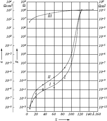
FIGURE 23.8
Tunnel resistivity for insulating “tunneling” films at metallic contact spots as a function of film thickness according to Holm (Figure. 26.11, p. 126 of Ref. [24]). Curve I, computed for very low voltages across the film, is most nearly applicable to the case of metal fiber brushes, while curve II represents average values up to 3 V across the films, and curve III is the classical resistivity for a ρ = 107 Ω m film material. Thus ordinary electrical conduction is negligible for insulating film thicknesses below 11 nm but becomes controlling above 13 nm.
Since much of fiber brush research has been conducted in intentionally moist environments, adsorbed moisture films have been studied in considerable detail using fiber bundles sliding painter’s brush-style in the “hoop apparatus” [85,86,87,88,89,90,91,92]. It was concluded that the relative motion between the two sides of contact spots takes place between the two close-packed layers of water molecules, each absorbed to its respective surface. In the absence of deliberate boundary lubrication, adsorbed moisture (and perhaps similarly adsorbed oxygen, nitrogen, or other gases) serves as boundary lubricant. Even in adhesive wear with plastic contact spots, the energy dissipation through friction likely occurs within the adsorbed layers and not via subsurface plastic deformation.
Fortunately in protective atmospheres containing water vapor, management of these surface tunneling films for successful metal fiber brush operation is typically easy to the point of being automatic. In almost all previous research on unlubricated metal fiber brushes in protective atmospheres, tunneling films have been double layers of adsorbed moisture of thickness s ~ 5 Å [36,38], although, in some cases, this condition has not been acknowledged (e.g., [93,94,95,96,97]). The same tunneling film is also present on graphitic lubricating films and on metal graphite brush contacts. The friction coefficient associated with this sliding between monolayers of adsorbed water presumably between most other monolayers is near Μ = 0.3. As a result, friction coefficients tend to be insensitive to the choice of sliding materials, and they are similarly insensitive to applied pressure.
As discussed, the ~ 5 Å thick moisture film at contact spots is extremely valuable for metal fiber brush operation since it is (close to) the thinnest conceivable surface film which prevents cold-welding and permits almost wear-less sliding at modest friction. A disruption of this film can occur when new surfaces are formed in confined conditions which inhibit moisture access, e.g., as in sliding wear under high pressures or in “fretting” wear. Disruption can also occur if the moisture layer may be evaporated through local heating near contact spots and may then not be replenished, or not be replenished fast enough. This depletion can be especially deleterious if ambient relative humidity is low or if a film is covering the contact region preventing ingress of moisture.
Unless other contact lubricants are present, wherever the critical double molecular moisture layer is disrupted or absent, cold-welding occurs virtually instantaneously with the corresponding severe wear damage. The supply of an adequate amount of moisture is, thus, essential for unlubricated metal fiber brush operation. And this is true whether or not they are used in conjunction with graphite since the graphite also requires moisture if it is not to “dust.” The limits of current density, sliding speed, and surface coverage with brushes which may be achieved while yet supplying enough moisture still need to be established.
Real world conditions usually do not allow particularly good control over the atmosphere surrounding the contacts. Ideally, one would like to preserve the “standard” two adsorbed monolayers of water, with σF = 10−12Ωm2, without any other surface coverage. However, in practice, virtually all films which form spontaneously from operation in standard environments on metals are insulating, their resistivity rises extremely rapidly with thickness in line with Figure 23.8 (compare also Chapter 1 and Ref. [98], for example), and they in turn are overlaid by adsorbed moisture. In fact, when the moisture is not firmly adsorbed in the metal matrix, it can create problems at temperatures below freezing by creating an insulating “slush.” Therefore, even films much too thin to be visible can give rise to brush resistances orders of magnitude higher than our “ideal” layer. The challenge in metal fiber brush construction and operation is how to maintain a reasonable surface film resistivity value, σF, in the presence of contaminants that make the formation of insulating solid surface films highly likely. This filming issue is the foremost problem for the use of fiber brushes in the open atmosphere.
Non-tarnishing metals such as aluminum, stainless steel, chromium, and nickel are not useful for low-resistance fiber brushes (although they may have important applications). They do not visibly oxidize because they are protected by an oxide film of 30 Å thickness or more, with the correspondingly high film resistivity. As to other base metals, their oxidation rates can vary greatly even if they are of similar chemical composition. One useful screening parameter for candidate fiber brush or counterface materials is the time dependence of film resistivity of the materials [98].
One solution is the use of noble metals. In particular gold, metals of the platinum group, and a large variety of their alloys are obvious selections although rather expensive. Proper alloy selection and the use of plating instead of solid noble metals can ameliorate this cost disadvantage. This use of noble metals is not a foolproof solution, and sometimes a contact lubricant is required. There are certain speed and electrical power profiles that require some lubrication strategy.
The use of fluid contact lubricants are sometimes required for some fiber brush solutions. As discussed in Chapter 22, one of the primary advantages of fluid lubricants is the establishment of a known film in the contact region. Kuhlmann-Wilsdorf points to two problems with fluid lubricants: (1) over the long sliding distances involved, they do not protect well enough against oxidation, and (2) since fluid lubricants are more viscous than water, they form thicker layers and, thereby, raise the film resistivity substantially. Both of these problems do exist, but they do not represent prohibitive problems.
Most contact lubricants will not protect copper and copper alloys from oxidation over time. This is the problem with using copper in applications that are sensitive to contact resistance in standard atmospheres with metal brushes. It is also true that there is normally a slightly higher contact resistivity with lubricated contacts than with unlubricated ones; however, in most practical cases this slightly higher value is acceptable. The true advantage of fiber brushes in most real world applications is the reduced wear debris and improved life and reliability. Even with a slight increase in film resistivity, the current density is higher than metal graphite monolithic brushes. Boundary lubrication with contact lubricants extends the usefulness of fiber brushes into industrial applications where moist argon and CO2 environments are not practical.
There is a fairly significant range of applications operating in standard industrial or military environments that utilize the advantages of fiber brushes benefiting from the use of noble metal contacts and specialty contact lubricants.
There are also options involving lubrication with solid lubricants. In principle a variety of different surface films could be considered, including MoS2. However, by far the most widespread electrically conductive protective layer to inhibit insulating film formation and facilitate electrical contacts is graphite. It is graphite that permits operation of monolithic brushes in the open atmosphere. Its advantages include freedom from environmental problems (except in relative humidity conditions of less than 15% or greater than 85%), nontoxicity to plants, animals, and humans, resistance to atmospheric attack, and being inexpensive and widely available. There has been some promising work on the in situ lubrication of brushes with graphite for low speed and low current densities [6,99]. Most of these tests were performed on solid metal brushes, and the testing that was done on a fiber brush was performed in moist CO2 atmosphere. Preliminary data suggests that the film resistivity is “high” resulting in low current density. It should be appreciated that “low current density” is relative. The low current density is the result of the higher resistivity of the graphite film which also exists with the next best option, metal graphite brushes, so, in fact, the “low current density” is relative to an ideal standard that is unattainable in standard environment [99].
The important point to understand in regards to surface films and lubrication is that moving fiber brushes into real world problem solutions involves making sound engineering trade-offs. In environments where contamination exists (i.e., most industrial environments), it is unlikely that the optimum 10−12 Ω m2 surface resistivity can be achieved. So the engineering issue is one of the combinations of materials, lubricants, and design features can be brought to bear to solve a real-world sliding electrical contact problem with a good solution—maybe not a perfect solution, but a good solution.
In general, the electrical resistance of brushes, RB, consists of three parts,
(23.9) |
or the sum of the resistance of the brush body, R0, the surface film resistance, RF, and the “constriction resistance,” RC. All three values are significant and need to be considered in any brush design. The constriction resistance, RC, is owing to the fact that all of the current has to pass through the contact spots. The current flow lines, therefore, have to constrict as they pass through the contact spots (as derived in considerable detail in Chapter 1). As a result, independent of brush type, indeed for any two objects which touch, the electrical effect of the current constriction through mechanical contact spots is much the same as if the contact spots were thin wires of a length equal to the contact spot diameter, 2a. For multiple contact spots starting with the standard Tabor equation A = F/H, the constriction resistance is approximately,
RC≈ρa(Ac/n)1/2/Ac=ρa/(Acn)1/2≈ρa(H/Pn)1/2 |
(23.10) |
Here, ρa is the averaged electrical resistivity of the two sides of the contact spots. On account of large n and small ρa for metal fiber brushes, Rc is negligible even if their running surface, AB, should be quite small. For example, for AB = 0.1 cm2 = 0.015 in2 with d = 50 Mm fibers occupying f = 10% of the volume, n ~ 500.
Film resistance cannot be avoided. Some nonmetallic film is necessary to prevent cold-welding and, thus, catastrophic gouging wear. If insulating, the current conduction through the thin films takes place by electron tunneling, and the dependence of constriction resistance on film thickness is very steep indeed, as shown in Figure 23.8 owing to Holm (Figure 26.11, p. 126 of Ref. [24]), but it is independent of the chemical nature of the film.
Kuhlmann-Wilsdorf discusses annular tunneling about contact spots as an advantage of fiber brushes [1,100]. Namely, the load-bearing part of a Hertzian contact spot is surrounded by an annular gap within which the separation between the two sides gradually increases. Current conduction is, therefore, not strictly limited to the load-bearing area, but occurs with rapidly diminishing intensity also via tunneling through the annular zone. In first approximation it may extend to a distance at which by purely geometrical construction the gap width, s, has increased to s* ≈ 5 Å [36,38]. Holm (p. 132 of Ref. [24]) had considered the effect theoretically, but concluded that it would always be insignificant. In the case of fiber brushes where the number of contact points is increased significantly above the number of contacting asperities in a monolithic brush, it could be expected that the effect could be moderately useful in increasing current capacity. References [36,38] can be used in the numerical evaluation.
23.4.1 Dependence of Electrical Resistance on Fiber Brush Construction
The brush resistance, RB, of a fiber brush of macroscopic area, AB, with elastic contact spots, subject to macroscopic pressure, pB, is found in a straightforward manner using [36, 38] as:
Rb=(ρFAbK2){(Epb)2(drc)270f}13 |
(23.11) |
The factor K2 is used to correct the film resistivity, ρF, for peripheral tunneling and a detailed description can be found in the references.
The assumption of this relationship is that the bulk resistance of the brush and the constriction resistance are negligible and that the brush resistance is equal to the film resistance, or, RB = RF. Not unexpectedly, except for the complication of the factor K2, the fiber brush resistance is proportional to ρFAb
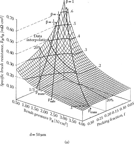
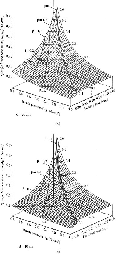
FIGURE 23.9
Theoretical specific brush resistances (RBAB) as a function of pressure (pB = P/AB) and packing fraction (f) for fiber diameters of (a) d = 50 Mm, (b) d = 20 Mm, and (c) d = 10 Mm, according to Equation 23.11, for copper (E = 1.2 × 10¹¹ N m−2). The highlighted packing fraction of f = 20% and brush pressures between psafe = ptrans/2 and ptrans/3, that is, 13≥β≤12
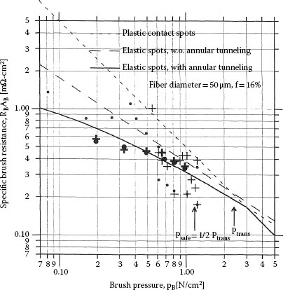
FIGURE 23.10
Specific resistances of four similar d = 50 μm, f ≈ 15% brushes in humid CO2. Each point represents the slope of a voltage–current curve drawn through measured data, taken in short succession at fixed speed and pressure with the current varied between about 10 and 90 Å. Heavy and light symbols refer to two different brush pairs in separate, uncooled testers with somewhat different loading springs and accuracies of force measurements. The heavy symbols pertain to the same brushes as Figure 23.2. Each pair consisted of one brush made of bare copper fibers, and one made of silver-plated copper fibers; one brush pair was tested on a bare copper rotor, the other on a gold-plated rotor. None of these minor permutations appears to have affected the brush resistance. The interpolation curves represent theoretically expected values for plastic contact spots with H = 5 × 10⁸ N m−2 (- - -), and for elastic spots without (–) and with (——) peripheral tunneling according to Equation 23.27, that is, assuming rc = d/2 and σF = 10−12 Ω m2 The latter is shown as the dotted line in Figure. 23.5(a). Dots (• and ●) indicate negative polarity, plus signs (+ and +) positive polarity. Ohm’s law was well obeyed.
Slip ring engineers are recognizing the importance of brush dynamics on the electrical and wear performance of slip rings and other sliding electrical contacts. Sliding contacts are spring loaded against their counterface. In the case of fiber brushes, this spring loading accommodates brush length changes as well as mechanical tolerances resulting in run-out (lack of perfect concentricity and irregular surface). The spring needs to ensure that the contact has the required brush pressure at the limit of brush wear and through the full extent of run-out tolerance. There is some spring loading from the fibers themselves as they are deflected onto the counterface. Figure 23.11 shows a diagram of a single fiber deflected and the force and dynamic properties of the spring can be calculated from standard beam deflection equations. As a matter of fact, most of the fiber brush work in the literature uses brushes that have no other spring mechanism. A certain force is exerted on the brush, and the brush is then locked into position. This is a useful approach as a research technique since precise force can be established, and it’s reasonable to assume a low run-out on the counterface.
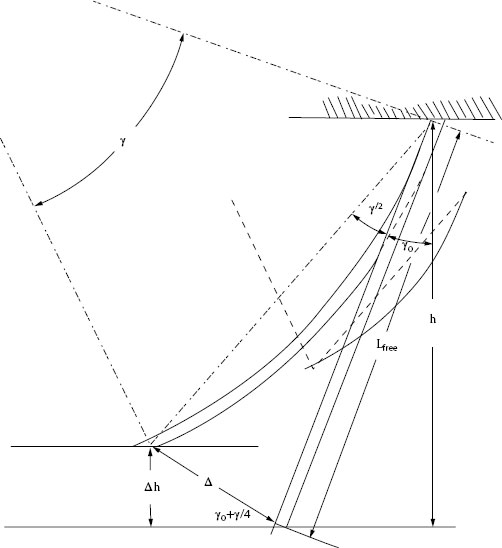
FIGURE 23.11
Geometry of free fiber length in a brush inclined by angle γ0 the contact surface and elastically bent through angle γ by its share of the applied brush force.
Incorporating fiber brushes into diverse applications, however, must involve a method of producing a reasonably constant force on the contact points through a wider range of tolerances and wear than this “hard mount” method can accommodate. The loading technique commonly used is though a spring. The loading spring can be a cantilever (see Figure 23.12b or a plunger style (Figure 23.12a). The point of this design is that the fibers themselves do not need to accommodate the total travel required during the life of the contact. This removes a design constraint that would make the design of a fiber brush almost impossible for certain applications. For example, the fiber brush similar to that shown in Figure 23.12b operates on a 1.5 m diameter slip ring used on a CT machine with the potential of over 1.0 mm of run-out. Designing a fiber brush without a primary loading spring would be very difficult.
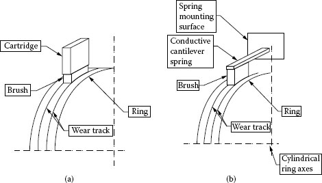
FIGURE 23.12
(a) and (b) show spring assemblies for a fiber brush as both a cartridge style or a cantilever style brush. The pictures are the same for either a composite brush or a fiber brush with the difference being the actual construction of the brush. The spring loading strategy is the same. Illustrations are from Chapter 22.
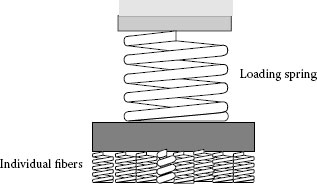
FIGURE 23.13
This diagram shows the spring model for a fiber brush that is independently loaded with a secondary spring. The secondary spring removes the design constraint that the compliance of the individual brush springs needs to accommodate all wear, mechanical alignment, and inertial forces.
The addition of the second loading spring does make the dynamic modeling more difficult. Figure 23.13 new brush spring model gives the schematic of this approach showing small parallel brush springs in series with the larger loading spring. The larger spring compliance needs to be higher than the compliance of the total of the parallel compliance of the small springs. Constant force springs can be used to provide a constant force through the complete range of travel, although the most common approach is to use a linear spring with sufficient compliance (inverse of spring rate) to provide an acceptable range of forces through the total travel. In the case of high speed operation, analysis should be performed to ensure that dynamic effects do not reduce the brush pressure below the minimum level of acceptable performance.
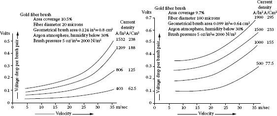
FIGURE 23.14
Speed dependence of gold fiber brush resistances between 3.5 m s−1 and 36 m s−1 in terms of voltage drop across different brush pairs at the indicated current densities in humid argon. (From C. Adkins and D. Kuhlmann-Wilsdorf, “Development of High Performance Metal Fiber Brushes II—Testing and Properties,” presented at the Holm Conference on Electrical Contacts—1979, Chicago IL, 1979 Figure 6 [36]. With permission.)
As suggested in Figure 23.11, it is usually advantageous to run fiber (on tip) brushes with a trailing angle and the recommendation is between 15o and 20o to allow smooth bending of the fiber when force is applied. This suggests that operation should be in one direction only. Tangential brushes can tolerate bi-directional operation.
The sliding speed of fiber brush contacts was discussed earlier in terms of thermal effects. But sliding speed also presents dynamic issues that should be addressed. Tests showing the dependence of electrical resistance on sliding velocity for two different gold-fiber brush pairs are shown in Figure 23.14. These brushes were tested under the same conditions, that is, in moist argon at pB = 2 × 10³ N m−2 (corresponding to β = 0.2), and were of similar construction with f ≈ 10%, but had different fiber diameters of d = 20 Mm and 100 Mm, respectively. It is obvious at first glance that the resistance under the conditions of Figure 23.8 rose substantially with speed, just about quadrupling between 5 and 35 ms−1 for the thinner fibers on the left and doubling for the 100 Mm fibers on the right. The likely explanation is hydrodynamic lift from surface films [36,38].
There are a number of very promising future directions for fiber brushes and most of them involve research into characterizing the performance of fiber brushes that can meet the requirements of standard industrial environments. This should extend the material range, lubrication options, design parameters (e.g., force, spring compliance, number, and length of fibers), and operational parameters of fiber brushes [100]. Careful attention should be given to the same developments listed in Chapter 22 from the nanotribologists that should provide support for lubrication, material, and design improvements to metallic sliding contacts.
Fiber brush technology can provide a solution for sliding contact applications that require low wear debris generation, long life without maintenance, and good electrical current density by utilizing multiple fibers impinging on the counterface with light contact force. Although much of the formal research has been with controlled environments, there are industrial and defense applications that support a more general application.
Dr. Kuhlmann-Wilsdorf started her fiber brush development about the same time I started designing slip ring assemblies. Dr. Norris Lewis and other colleagues in Blacksburg, VA, were familiar with her work, and we started integrating fiber brush techniques into our slip ring designs although our approach diverged significantly from her guidelines. Dr. Kuhlmann-Wilsdorf recently passed away, and I hope in this update to her chapter to show the broader application of her theories to general slip ring applications than she indicated in the original chapter. To do this, I have de-emphasized the considerable body of funded work done for the Navy in support of very high current requirements. As I said in the introduction, this very high current work pushed many of the advantages of the fiber brush approach into the background. But the general application of the fiber brush basics do require “push back” on many of Dr. Kuhlmann-Wilsdorf’s main assumptions. The extensive equation derivation in the original chapter were for the very specific Kuhlmann-Wilsdorf fiber brush design and have very limited application to the problem of designing a fiber brush for general use. I have significantly reduced the number of equations and instead provided references for those interested. I have tried to show how Dr. Kuhlmann-Wildsdorf’s basic principles have a much broader scope and application than she acknowledged. Those readers interested in fiber brushes for homopolar motors will probably be disappointed; readers interested in a modestly high current density, high reliability, low maintenance, long life brush for general industrial environments should be encouraged. Thanks to Becky Wills for editorial and graphic assistance.
Appendix A.1 Collection of Important Equations
The equations found in this appendix are a comprehensive collection of relationships derived by Kuhlmann-Wilsdorf for a specific fiber brush design [101]. The assumptions made for this brush design are listed in the Introduction but are included here for ease of reference. References are included that provide a more thorough discussion of the equations and their derivations. Appendix A.2 provides the description of the symbols used.
1. Fiber brushes are used for transmitting high current and the critical electrical parameters is related to conductivity.
2. Fiber brushes are relatively large bundles of very small (sub 100 μm. diameter), independently-acting fibers with their tips impinging on the counterface. The brush has been described as a “velvet-like mat” made of fibers.
3. The bulk brush length is short and the bulk resistance of the brush is insignificant compared to the contact resistance.
4. The environment and consequentially surface films are well controlled and the resistivity is roughly 10−12 ohms/m2 or equal to 2 molecular layers of water. In most cases this requires a controlled atmosphere to achieve.
5. Fluid lubrication is never used.
6. Normal forces are equally distributed across individual fibers and the fibers are small enough that there is only one contact spot per fiber.
7. Contact spots can be evaluated using the Hertz criteria as elastic or plastic and a critical brush pressure can be determined where the contacts transition from elastic to plastic; low wear occurs under this transition pressure.
All Fibers Touch the Substrate, One Elastic Contact Spot per Fiber
Basic Properties of Contact Spots Ref. [3, 36, 38, 41]
Number of contact spots per unit area: n*=f/(14πd2)
Contact spot radius: ael=1.1(rcpB/n*E)1/3=1.1d(πβ 1.2×10⁻⁶/8)1/3≈8.6×10−3β1/3d
“Transition” and “safe” pressures: ptrans=2psafe≈3×10⁻⁴f H≈1.2×10⁻⁶ f E
Total contact spot area: AC=n*ABa2el≈3×10⁻⁴ β2/3 f AB
Pressure at contact spot: pe1c(β)=β1/3 H≈0.04β1/3 E
Force per fiber-end: Ffiber=βπd2 ptrans/4f=1.2×10−6 βπd2E/4
Electrical Resistances Ref. [3, 36, 38, 41]
Brush resistance =R0+RC+RB≈RB
Brush body resistance: R0=ρBLfiber/f AB
Brush constriction resistance: RC=ρa/(nAC)1/2=51ρad/(β1/3f AB)
Film resistance: RB=(σF/ABK2){(E/ρB)2(d/rc)2/(70f)}1/3
RB for the typical case that rc = d/2 and σF = 10−12 Ω m2, using pB = βptrans
RB≈(σF/ABK2)3.4×103 /f β2/3 ≈0.034 [mΩcm2]/(K2 fβ2/3
Film resistivity for rc=d/2 and K2 = 1.15: σF=3.4×10⁻⁴f RB[mΩ]AB[cm2]β2/3 from (23.27)
Equivalent length (length of a solid piece of metal of same electrical resistance): Requiv=ρBLequiv/AB
Equivalent length of body resistance: iLO′ equiv=Lfiber/f=5Lfiber/ϕ
Equivalent length of constriction resistance, in general and specifically for ρa=ρB with β=12: iLC, equiv=51 d(ρa/ρB)(β1/3f)=0.016(δ/ϕ)[m](ρa=ρb, β=12)=1.6[cm]standard
As above, but for the film resistance in general and with ρB=1.65×10⁻⁸Ωm and β = 1/2: iLF, equiv=3.4×10³(σ0/ρBK2)(β2/3f)=1.03s/(β2/3ϕ)[m]=1.64[m]standard
wo=(Δℓ/Ls)o≈10−9β4.6
Losses, Flash Temperatures, and Bulk Heating Through the Brush Body Ref. [3, 41, 44, 55,56,57,58,59,60]
Mechanical loss per unit of current: LM=μvP/i=μvpB/j=WM/j
Electrical loss per unit of current: LE=RBi=RBABj=WE/j
Total power loss per unit area: W=WM+WE=μpBv+RBABj2=3×10⁻⁴βf Hμv+(σF/K2)3.4×103 j2/(fβ2/3)
Flash temperature: ΔT=[F(Z,S)/λB]{6.8×10−3β2/3Hμvd+(σF/K2)(7.71×104d j2/f2β)}
Relative pressure for which LM = LE, at which W as well as ΔT are close to their minimum
βmin≈1.71×10⁴(σF/K2)j2/(Hμvf2)}3/5
Flash temperature near βmin: ΔTmin=[F(Z,S)/λB]9.02{σ2FH3μ3/f2K2}1/5dv3/5j4/5
As above, but for “standard brush” at slow speed: ΔT*min=3.01×10⁻⁶j4/5v3/5
Total equivalent voltage loss for “standard brush” near βmin: L*T,min=1.76×10⁻³(jv2)1/5
Relative contribution to flash temperature through brush bulk heating: ΔTave/ΔTspot=(vave/vspot)0.78[cm−1]ϕβ1/3D∥/δ
Heat conduction through brush body: Wcond=fλBΔTcond/Lfiber=72ϕℓ(ΔTcond/Lfiber)
Equivalent length in regard to heat transfer through fiber brush material: LhF,equiv=3.4×10³(tFilmλB/λFK2)/(β2/3f)=(1/ϕ)1.7×107×tFilm[m]standard
Brush Body Construction: Only the Fraction ξ of Fibers “Track” Ref. [101]
Body brush resistance: RO(ξ)=RO/ξ
Constriction resistance: RC(ξ)=RC/ξ2/3
Film brush resistance: RB(ξ)=RB/ξ1/3
Equivalent lengths of body resistance: Lio,equiv(ξ)=5Lfiber/ξϕ={5Lfiber/ξ}standard
constriction resistance: LiC,equiv(ξ)=0.0168/(ϕξ2/3)[m](ρa=ρb, β=1/2)={0.016/ξ2/3}[m]standard
film resistance: iLF,equiv(ξ)=1.03s/(β2/3ϕξ1/3[m]={1.64/ξ1/3}[m]standard
Value of ξ below which the body resistance becomes larger than the film resistance: ξo=F≈{5 Lfiber[m]/1.64ϕ[m]}3/2
Wear: (Δℓ/Ls)ξ≈(Δℓ/Ls)o/ξ4.6≈10−9(β/ξ)4.6
Variation of wear rate with small variations of local pressure: δ(Δℓ/Ls)/(Δℓ/Ls)=(2×4.6×5.6)δβ/β =51.5δβ/β
Brush Body Construction: Limitations Through Elastic Fiber Flexing Ref. [101]
Difference of gap width through surface undulation, accommodated through fiber flexing of: Δh=Δ sin(γ0+γ/4)≈Δ√2
Average fiber flexing owing to brush pressure (A = Lfree/d = aspect ratio): Δ=1.95×10⁻⁶βL3free/d2=1.95×10−6βA2Lfree=1.95×10−6βA3d
Maximum amplitude of substrate undulations compatible with full “tracking” (maximum elastic strain 2×10⁻⁴≤∈max≤5×10⁻³: Ψmax[rad]=Δh/vτ=312∈max/v=3.6∘/v[ms−1]≤Ψ∘max≤89.4∘/v[ms−1]
Maximum speed with full tracking in the “fundamental” oscillation mode: 3.6∘[ms−1]/Ψ∘≤vmax≤89.4∘[ms−1]/ψ∘
ael |
Radius of average elastic contact spot |
apl |
Radius of average plastic contact spot |
A |
Aspect ratio of free fiber length, i.e. Lfree/d |
AB |
Area of macroscopic brush/substrate interface |
AC |
Total area of contact spots; P/H or Equation 23.45 in the plastic or elastic case |
Apl |
Total area of plastic contact spots (equal to P/H) |
B |
Factor to correct flash temperature for overall brush heating |
C |
Specific heat |
D |
Fiber diameter |
D |
Mechanical density of brush or substrate material |
D∥≈(4AB/π)1/2 |
Brush diameter in sliding direction |
E |
Ellipticity of contact spot (ratio of long to short axis) |
E |
Averaged Young’s modulus of brush and substrate materials |
F |
Packing fraction, percentage of metal in brush volume at interface |
Ffiber |
Force applied to a fiber end, deflecting it by Δ normal to its axis |
F(Z, S) |
Factor (≤ 1) by which flash temperature is reduced compared to ΔT0, i.e., of an asperity on an insulating substrate at zero velocity |
H |
Hardness of brush material in units of 5 × 10⁸N/m2, the average hardness of copper |
H |
Meyer hardness of brush or substrate, whichever is the smaller |
I |
Current conducted through brush |
j=i/AB |
Current density through brush |
K* |
Dimensionless constant in the Holm-Archard wear law |
KHA |
K* when expressed in terms of dimensionless wear |
K2 Factor by which σF |
must be divided to correct for peripheral tunneling |
K2safe Probable value of K2 |
at the safe pressure, psafe |
ℓ |
The thermal conductivity of the brush material in units of λCu |
LE |
Electrical brush loss per ampere conducted |
LE* LE |
for the “standard case,” that is, s = h = m = φ = ℓ = δ = v = 1 |
Lfiber |
Fiber length from contact spot to brush current connection |
Lfree |
Free fiber length between the interface and the nearest fixed point |
hLj,equiv |
Same as iLj.eqiuv but in regard to heat transfer resistance |
iLj,equiv |
Length of solid fiber brush material of same electrical resistance (subscripts j = O, C, or F for body, constriction and film resistance, respectively) |
LM |
Mechanical brush loss per ampere conducted |
LM* LM |
for the “standard case,” i.e., s = h = m = φ = ℓ = υ = v = 1 |
Lmin |
Minimum loss per ampere conducted, obtained by adjusting pressure to βmin so that LE = LM |
Ls |
Sliding distance |
Lsoft |
Loss per ampere conducted equal to Holm’s “softening voltage” (equal to 0.12V for copper) |
LT=LE+LM |
Total brush loss per ampere conducted |
LT,min |
The total loss per ampere conducted at βmin, i.e. when the pressure is adjusted to obtain LM = LE |
M |
The coefficient of friction in units of 0.35, its conservative value |
m* |
Number of spot diameters through which, on average, a contact spot slides before it forms a wear particle |
N |
Number of contact spots at brush/substrate interface |
n* |
Number density of contact spots at brush/substrate interface |
P |
Macroscopic pressure at interface between sliding solids |
pB |
Brush pressure: P/AB |
pBmin= βminptrans |
Brush pressure at which the total heat evolution is (nearly) minimized |
pcontact |
Average local pressure at contact spots |
pelc=β1/3H |
Average local pressure at elastic contact spots |
pplc=H |
Average local pressure at plastic contact spots |
psafe=12ptrans |
Brush pressure at which expected dimensionless wear is in the 10−10 range |
ptrans |
Value of pB (namely ≈ 3 × 20−4 fH) at the transition between elastic and plastic contact spots |
P |
Normal force between brush and substrate |
Ptrans |
Value of P at ptrans i.e., the transition between elastic and plastic contact spots |
Q |
Local heat evolution at contact spots per unit area and time |
qave |
Average heat evolution at brush-substrate interface per unit area and time |
R |
Characteristic dimension of contact spot (i.e., normally its radius) |
rc |
Radius of the asperity forming an elastic, “Hertzian” contact spot (in fiber brushes, normally rc ≈ d/2) |
RB |
Electrical resistance of a brush, in a well-constructed metal fiber brush equal to RF |
RBmin |
Brush resistance at condition of minimum loss, i.e., at pB = βminPtrans |
RC |
Constriction resistance of a brush |
RF |
Film resistance of a brush |
RO |
Electrical resistance of the brush body |
S |
σF/K2 in units of 10−22 Ω m2, the most common value of σF |
s* |
Gap width through which effective tunneling can take place (~ 0.5 nm) |
S(e,v) |
Function by which the flash temperature is modified on account of contact spot ellipticity |
tFilm |
Thickness of surface film |
V |
Sliding velocity of brush on substrate |
vcrit |
Highest sliding velocity at which LE = LM can be achieved for V < Vsoft |
v0=κB/r |
Characteristic velocity |
vr=v/v0 |
Relative velocity (Peclet number) |
vrB |
Relative velocity of contact spots on substrate (almost always = vr) |
vrS |
Relative velocity of contacts spots on brush (almost always = 0) |
V |
Wear volume |
Vmelt |
“Melting voltage” as defined by Holm, see Table 23.2 |
Vsoft |
“Softening voltage” as defined by Holm, see Table 23.2 |
W |
Heat developed per unit area and time at the brush/substrate interface |
Wcond |
Heat conducted per unit area and time through fiber brush from interface to cooled fiber-end |
WE |
Rate of electrical heat evolution, i.e., the part of W owing to Joule heat |
WM |
Rate of mechanical heat evolution, i.e., the part of W owing to friction |
Z0 |
Function describing the velocity dependence of contact spots for e = 2 and λr = 0 |
*(Asterisk) |
Pertaining to the “standard brush” with s = h = m = φ = ℓ = δ = v = 1 |
A |
Number of contact spots per fiber end |
B |
Ratio pB/ptrans |
βmin |
The value of β yielding equal friction and Joule heating, approximating the condition of minimum flash temperature as well as minimum heat loss |
βsafe |
The β-value (namely 12) believed to confer wear rates Δℓ/Ls<10−10 |
Γ |
Average bending angle of the free fiber lengths on account of applied force |
γ0 |
Angle of inclination of brush body relative to the sliding interface |
Δ |
The fiber diameter in units of 50 Mm, its most typical value |
Δβ |
Incidental local change of β at fiber-ends on account of surface undulations |
Δ |
Elastic deflection of fiber end at interface, normal to Lfree |
Δh |
Decrease of distance between the interface and the nearest fixed fiber point on account of elastic flexing of fiber length Lfree |
Δℓ |
Reduction of brush length through wear |
Δℓ/Ls |
Dimensionless wear rate |
ΔT |
“Flash temperature”: Rise of contact spot temperature above ambient |
ΔTave |
Temperature rise at fiber brush as a whole |
ΔTcond |
Temperature drop owing to heat conduction from interface to cooled end of fiber brush |
ΔTcor=BΔT |
Flash temperature corrected for superimposed overall brush heating |
ΔTE |
Contribution to flash temperature through Joule heat |
ΔT*E ΔTE |
for the “standard case” of s = h = m = φ = ℓ = δ = v = 1 |
ΔTM |
Contribution to flash temperature through friction heat |
ΔT*M ΔTM |
for the “standard case” of s = h = m = φ = ℓ = δ = v = 1 |
ΔTmin |
Near-minimum flash temperature, obtained at WM = WE or equivalents LM = LE, at which also W is nearly minimized |
ΔT*min ΔTmin |
for the “standard case” of s = h = m = φ = ℓ = δ = v = 1 |
ΔT0=πqr/4λB |
Flash temperature at zero velocity on a thermally insulating substrate |
ΔMTave |
Temperature rise at monolithic brush as a whole |
ΔMTspot |
Flash temperature at contact spot of monolithic brush |
Δρa |
Averaged electrical resistivity of brush and substrate materials |
κ=λ/Dc |
Thermal diffusivity |
κB=λB/DBcB |
Thermal diffusivity of brush material |
Λ |
Thermal conductivity |
λB |
Thermal conductivity of brush material |
λF |
Thermal conductivity of surface film material |
λr=λS/λB |
Relative thermal conductivity of substrate material relative to brush material |
λS |
Thermal conductivity of substrate material |
M |
Coefficient of friction |
V F(Z, S) |
in units of 12, its value for copper slowly sliding on copper |
vave |
v for the brush as a whole |
vspot |
v for the average individual contact spot |
Ξ |
Fraction of fiber ends which actually touch the substrate |
ρa |
Average electrical resistivity of substrate and fiber material |
ρB |
Electrical resistivity of fiber material |
σF |
Specific resistivity of surface film at contact spots, in units of flm2 |
σF/K2 |
Surface film resistivity as modified by peripheral tunneling |
τ |
Period of mechanical oscillation of fiber ends |
Φ |
The packing fraction, f, in units of 0.2, its “standard” value |
Ψ |
Angular local deviation from planarity of the interface |
1. D. Wilsdorf, “Versatile Electrical Fiber Brush and Method of Making,” USA Patent 4,358,699, Nov. 9, 1982, 1982.
2. N. Argibay, J.A. Bares, J.H. Keith, G.R. Bourne, and W.G. Sawyer, “Copper–beryllium metal fiber brushes in high current density sliding electrical contacts,” Wear, vol. 268, pp. 1230–1236, 2010.
3. D. Kuhlmann-Wilsdorf, “Electrical fiber brushes-theory and observations,” Components, Packaging, and Manufacturing Technology, Part A, IEEE Transactions on, vol. 19, pp. 360–375, 1996.
4. J. ABares, NArgibay, NMauntler, G.J. Dudder, S.S. Perry, G.R. Bourne, and W.G. Sawyer, “High current density copper-on-copper sliding electrical contacts at low sliding velocities,” Wear, vol. 267, pp. 417–424, 2009.
5. N. Argibay, J.A. Bares, and W.G. Sawyer, “Asymmetric wear behavior of self-mated copper fiber brush and slip-ring sliding electrical contacts in a humid carbon dioxide environment,” Wear, vol. 268, pp. 455–463, 2010.
6. J. ABares, “Lubrication of High Current Density Metallic Sliding Electrical Contacts,” PhD, University of Florida, 2009.
7. N. Argibay and W.G. Sawyer, “Low wear metal sliding electrical contacts at high current density,” Wear, vol. 274–275, pp. 229–237, 2012.
8. G. Dorsey, Application Note 207: Fiber Brushes: The Low Maintenance, Long Life, High Power Slip Ring Contact. Blacksburg, VA, Moog Components Group, 2005.
9. G. Dorsey, Application Note 203: Fiber Brushes: The Maintenance-Free Wind Turbine Slip Ring Contact Material. Blacksburg, VA, Moog Components Group, 2005.
10. N. Lewis and J.A. Skiles, “Fiber Brush Slip Ring Assembly,” USA Patent 4398113, Aug 9, 1983, 1983.
11. E. Rabinowicz, Friction and Wear of Materials. New York: John Wiley & Sons, 1965.
12. P. Blau, Friction and Wear Transitions of Materials. Park Ridge, NJ: Noyes Publications, 1989.
13. N. AAlcantar, CPark, J.-M. Pan, and J.N. Israelachvili, “Adhesion and coalescence of ductile metal surfaces and nanoparticles,” Acta Materialia, vol. 51, pp. 31–47, 2003.
14. B. Bhushan, JIsraelachvili, and ULandman, “Nanotribology: friction, wear and lubrication at the atomic scale,” Nature, vol. 374, pp. 607–616, 1995.
15. M. LGee, P.M. McGuiggan, J.N. Israelachvili, and A.M. Homola, “Liquid to solidlike transitions of molecularly thin films under shear,” The Journal of Chemical Physics, vol. 93, pp. 1895–1906, 1990.
16. A. MHomola, J.N. Israelachvili, P.M. McGuiggan, and M.L. Gee, “Fundamental experimental studies in tribology: The transition from “interfacial” friction of undamaged molecularly smooth surfaces to “normal” friction with wear,” Wear, vol. 136, pp. 65–83, 1990.
17. J. Israelachvili, SGiasson, TKuhl, CDrummond, ABerman, GLuengo, J.M. Pan, MHeuberger, WDucker, and NAlcantar, “Some fundamental differences in the adhesion and friction of rough versus smooth surfaces,” in Tribology Series. vol. 38, DDowson, Ed., Elsevier, 2000, pp. 3–12.
18. J. Israelachvili, P.M. McGuiggan, MGee, A.M. Homola, M.O. Robbins, and P.A. Thompson, “Liquid dynamics in molecularly thin films,” Journal of Physics. Condensed Matter, vol. 2, pp. 89–98, 1990.
19. J. NIsraelachvili, P.M. McGuiggan, and A.M. Homola, “Dynamic properties of molecularly thin liquid films,” Science, vol. 240, pp. 189–191, 1988.
20. M. Urbakh, JKlafter, DGourdon, and JIsraelachvili, “The nonlinear nature of friction,” Nature, vol. 430, pp. 525–528, 2004.
21. G. GAdams, “The Mechanics of Adhesion: A Tutorial,” ASME Conference Proceedings, vol. 2008, pp. 87–89, 2008.
22. G. GAdams, “The mechanics of adhesion: current and future research trends,” ASME Conference Proceedings, vol. 2008, pp. 91–93, 2008.
23. R. Holm, “Über Metallische Kontaktwiderstände. Wiss Veröff.,” Siemens Werke 7/2: 217,1929.
24. RHolm, Electric Contacts, Theory and Applications, 4th ed. Berlin, Heidelberg, New York: Springer-Verlag, 1967.
25. J. FArchard, “Contact and rubbing of flat surfaces,” Journal of Applied Physics, vol. 24, pp. 981–988, 1953.
26. X. Yin and KKomvopoulos, “An adhesive wear model of fractal surfaces in normal contact,” ASME Conference Proceedings, vol. 2008, pp. 529–531, 2008.
27. Y. JChang and DKuhlmann-Wilsdorf, “A case of wear particle formation through shearing-off at contact spots interlocked through micro-roughness in “adhesive” wear,” Wear, pp. 175–197, 1987.
28. J. Song and DSrolovitz, “Material effect in material transfer in mechanical contacts,” Acta Materialia, vol. 54, pp. 5305–5312, 2006.
29. Y. Du, LChen, N.E. McGruer, G.G. Adams, and IEtsion, “A finite element model of loading and unloading of an asperity contact with adhesion and plasticity,” Journal of Colloid and Interface Science, vol. 312, pp. 522–528, 2007.
30. Y. Du, G.G. Adams, N.E. McGruer, and IEtsion, “A parameter study of separation modes of adhering microcontacts,” Journal of Applied Physics, vol. 103, pp. 064902–064909, 2008.
31. D. Maugis and H.M. Pollock, “Surface forces, deformation and adherence at metal microcontacts,” Acta Metallurgica, vol. 32, pp. 1323–1334, 1984.
32. R. LJackson and IGreen, “On the modeling of elastic contact between rough surfaces,” Tribology Transactions, vol. 54, pp. 300–314, 2011/01/10 2011.
33. M. Ciavarella, CMurolo, and GDemelio, “On the elastic contact of rough surfaces: Numerical experiments and comparisons with recent theories,” Wear, vol. 261, pp. 1102–1113, 2006.
34. G. Carbone and FBottiglione, “Asperity contact theories: Do they predict linearity between contact area and load?,” Journal of the Mechanics and Physics of Solids, vol. 56, pp. 2555–2572, 2008.
35. X. Yin and KKomvopoulos, “An adhesive wear model of fractal surfaces in normal contact,” International Journal of Solids and Structures, vol. 47, pp. 912–921, 2010.
36. C. Adkins and DKuhlmann-Wilsdorf, “Development of High Performance Metal Fiber Brushes II—Testing and Properties,” Presented at the Holm Conference on Electrical Contacts—1979, Chicago IL, 1979.
37. C. Adkins and DKuhlmann-Wilsdorf, “Development of High Performance Metal Fiber Brushes 2—Background and Manufacture,” Holm Conference on Electrical Contacts, pp. 165–170, 1979.
38. C. Adkins and DKuhlmann-Wilsdorf, “Development of High Performance Metal Fiber BrushesIII—Further Tests and Theoretical Evaluation,” Holm Conference on Electrical Contacts, pp. 67–72, 1980.
39. W. EWilson, S.V. Angadi, and R.L. Jackson, “Surface separation and contact resistance considering sinusoidal elastic–plastic multi-scale rough surface contact,” Wear, vol. 268, pp. 190–201, 2010.
40. W. Yan and KKomvopoulos, “Contact analysis of elastic-plastic fractal surfaces,” Journal of Applied Physics, vol. 84, pp. 3617–3624, 1998.
41. D. Kuhlmann-Wilsdorf, “Uses of theory in the design of sliding electrical contacts,” in Electrical Contacts, 1991. Proceedings of the Thirty-Seventh IEEE Holm Conference on, pp. 1–24, 1991.
42. L. Brown, DKuhlmann-Wilsdorf, and WJesser, “Testing and evaluation of metal fiber brush operation on slip rings and commutators,” Components and Packaging Technologies, IEEE Transactions on, vol. 31, pp. 485–494, 2008.
43. E. IShobert, Carbon Brushes: The Physics and Chemistry of Sliding Contacts. New York: Chemical Publishing Company, Inc., 1965.
44. D. Kuhlmann-Wilsdorf, “Temperatures at interfacial contact spots: Dependence on velocity and on role reversal of two materials in sliding contact,” Journal of Tribology, vol. 109, pp. 321–329, 1987.
45. M. Kalin, “Influence of flash temperatures on the tribological behaviour in low-speed sliding: a review,” Materials Science and Engineering: A, vol. 374, pp. 390–397, 2004.
46. J. CJaeger, “Moving sources of heat and the temperature at sliding contacts,” in Proc Roy Soc, New South Wales 56, 1942, pp. 203–224.
47. H.S. Carslaw, The Conduction of Heat in Solids. London: Oxford University Press, 1959.
48. H. Blok, “Theoretical study of temperature rise at surfaces of actual contact under oiliness lubricating condition.” Proceedings of the Institution of Mechanical Engineers 2: 222–235, 1937.
49. J. FArchard, “The temperature of rubbing surfaces,” Wear, vol. 2, pp. 438–455, 1959.
50. R. ABurton, “Thermal deformation in frictionally heated contact,” Wear, vol. 59, pp. 1–20, 1980.
51. J. RBarber, “The conduction of heat from sliding solids,” International Journal of Heat and Mass Transfer, vol. 13, pp. 857–869, 1970.
52. E. Rabinowicz, “The temperature rise at sliding electrical contacts,” Wear, vol. 78, pp. 29–37, 1982.
53. M. Kalin and JVižintin, “Comparison of different theoretical models for flash temperature calculation under fretting conditions,” Tribology International, vol. 34, pp. 831–839, 2001.
54. B. Vick and M.J. Furey, “A basic theoretical study of the temperature rise in sliding contact with multiple contacts,” Tribology International, vol. 34, pp. 823–829, 2001.
55. D. Kuhlmann-Wilsdorf, “Demystifying flash temperatures IAnalytical expressions based on a simple model,” Materials Science and Engineering, vol. 93, pp. 107–118, 1987.
56. D. Kuhlmann-Wilsdorf, “Demystifying flash temperatures I.I. First-order approximation for plastic contact spots,” Materials Science and Engineering, vol. 93, pp. 119–133, 1987.
57. D. Kuhlmann-Wilsdorf, “Flash temperatures due to friction and Joule heat at asperity contacts,” Wear, vol. 105, pp. 187–198, 1985.
58. D. Kuhlmann-Wilsdorf, D.D. Makel, and N.A. Sondergaad, Refinement of flash temperature calculations, in F.A. Smidt and P.J. Blau (eds.), Engineered Materials for Advanced Friction and Wear Applications, ASM International, Metals Park, OH, pp. 23–32, 1988.
59. D. Kuhlmann-Wilsdorf, “Sample calculations of flash temperatures at a silver-graphite electric contact sliding on copper,” Wear, vol. 107, pp. 71–90, 1986.
60. D. Kuhlmann–Wilsdorf, “Theoretical speed and current density limits for different types of electrical brushes,” Magnetics, IEEE Transactions on, vol. 20, pp. 340–343, 1984.
61. D. GBansal and J.L. Streator, “Design curves for temperature rise in sliding elliptical contacts,” Tribology International, vol. 42, pp. 1638–1650, 2009.
62. D. GBansal and J.L. Streator, “A method for obtaining the temperature distribution at the interface of sliding bodies,” Wear, vol. 266, pp. 721–732, 2009.
63. D. GBansal and J.L. Streator, “On estimations of maximum and average interfacial temperature rise in sliding elliptical contacts,” Wear, vol. 278–279, pp. 18–27, 2012.
64. X. Tian and F.E. Kennedy, “Maximum and average flash temperatures in sliding contacts,” Journal of Tribology, vol. 116, pp. 167–174, 1994.
65. W. WChen, Q.J. Wang, and WKim, “Transient thermomechanical analysis of sliding electrical contacts of elastoplastic bodies, thermal softening, and melting inception,” Journal of Tribology, vol. 131, pp. 021406–021410, 2009.
66. S. Liu and QWang, “Studying contact stress fields caused by surface tractions with a discrete convolution and fast Fourier Transform algorithm,” Journal of Tribology, vol. 124, pp. 36–45, 2002.
67. C. Jacq, DNelias, GLormand, and DGirodin, “Development of a three-dimensional semi-analytical elastic-plastic contact code,” Journal of Tribology, vol. 124, pp. 653–667, 2002.
68. S. Kim, “Environmental Effects in Tribology,” in Micro- and Nanoscale Phenomena in Triboloty, YChung, Ed., Boca Raton, FL: CRC Press, 2012, p. 210.
69. A. MHomola, J.N. Israelachvili, M.L. Gee, and P.M. McGuiggan, “Measurements of and relation between the adhesion and friction of two surfaces separated by molecularly thin liquid films,” Journal of Tribology, vol. 111, pp. 675–682, 1989.
70. B. N.J. Persson and ETosatti, Physics of Sliding Friction vol. Series E: Applied Sciences. Dordrecht/Boston/London: Kluwer Academic Publishers, 1995.
71. W. Campbell, “The lubrication of electrical contacts,” Components, Hybrids, and Manufacturing Technology, IEEE Transactions on, vol. 1, pp. 4–16, 1978.
72. K. Komvopoulos, NSaka, and N.P. Suh, “The mechanism of friction in boundary lubrication,” Journal of Tribology, vol. 107, pp. 452–462, 1985.
73. SAndersson, ASöderberg, and SBjörklund, “Friction models for sliding dry, boundary and mixed lubricated contacts,” Tribology International, vol. 40, pp. 580–587, 2007.
74. K. Singh, SBaghmar, JSharma, M.V. Khemchandani, and Q.J. Wang, “Boundary lubrication and its stability,” ASME Conference Proceedings, vol. 2008, pp. 229–231, 2008.
75. R. Holm, “The electric tunnel effect across thin insulator films in contacts,” Journal of Applied Physics, vol. 22, pp. 569–574, 1951.
76. J. AGreenwood, “Constriction resistance and the real area of contact,” British journal of applied physics, vol. 17, pp. 1621–1632, 1966.
77. L. Boyer, “Contact resistance calculations: generalizations of Greenwood’s formula including interface films,” Components and Packaging Technologies, IEEE Transactions on, vol. 24, pp. 50–58, 2001.
78. S. Lee, HCho, and JYong Hoon, “Multiscale electrical contact resistance in clustered contact distribution,” Journal of Physics D: Applied Physics, vol. 42, pp. 165302–165308, 2009.
79. L. Kogut and KKomvopoulos, “Analytical current-voltage relationships for electron tunneling across rough interfaces,” Journal of Applied Physics 97, pp. 73701–1/73701–5, 2005.
80. L. Kogut, “Electrical performance of contaminated rough surfaces in contact.” Journal of Applied Physics 97(10): pp. 10372–1/10372–5, 2005.
81. G. Norberg, SDejanovic, and HHesselbom, “Contact resistance of thin metal film contacts,” Components and Packaging Technologies, IEEE Transactions on, vol. 29, pp. 371–378, 2006.
82. Z. Peng, Y.Y. Lau, WTang, M.R. Gomez, D.M. French, J.C. Zier, and R.M. Gilgenbach, “Contact resistance with dissimilar materials: bulk contacts and thin film contacts,” in Electrical Contacts (Holm), 2011 IEEE 57th Holm Conference on, 2011, pp. 1–6.
83. C. Pradille, FBay, and KMocellin, “An experimental study to determine electrical contact resistance,” in Electrical Contacts (HOLM), 2010 Proceedings of the 56th IEEE Holm Conference on, 2010, pp. 1–5.
84. P. Zhang, Y.Y. Lau, and R.M. Gilgenbach, “Thin film contact resistance with dissimilar materials,” Journal of Applied Physics, vol. 109, pp. 124910–1–12490–10, 2011.
85. C. Gao and DKuhlmann-Wilsdorf, “Observations on the effects of surface morphology on friction and sliding modes,” in Tribology of Composite Materials, ed Metals Park, Ohio: Am. Soc. for Metals Intl., 1990, pp. 195–201.
86. C. Gao and DKuhlmann-Wilsdorf, “On stick-slip and the velocity dependence of friction at low speeds,” Trans. ASME JTribology, vol. 112, pp. 354–360, 1990.
87. C. Gao and DKuhlmann-Wilsdorf, “Experiments on, and a Two-component Model for, the Behavior of Water Nano-films on Metals,” in Thin Films: Stresses and Mechanical Properties II, M.F. Doerner, W.C. Oliver, G.M. Pharr, and F.R. Brotzen, eds., Pittsburgh, PA: Materials Research Society, 1990, pp. 237–242.
88. C. Gao and DKuhlmann-Wilsdorf, “Adsorption films, humidity, stick-slip and resistance of sliding contacts,” in Electrical Contacts 1990, Proceedings of the Thirty-Sixth IEEE Holm Conference on Electrical Contacts, Piscataway, NJ, 1990, pp. 292–300.
89. C. Gao and DKuhlmann-Wilsdorf, “Adsorption films, humidity, stick-slip and resistance of sliding contacts,” in IEEE Transactions on Components, Hybrids, and Manufacturing Technology, pp. 37–44, 1991.
90. C. Gao and DKuhlmann-Wilsdorf, “On the tribological behavior of adsorbed layers, especially moisture,” Wear, vol. 149, pp. 297–312, 1991.
91. C. Gao, DKuhlmann-Wilsdorf, and D.D. Makel, “Moisture effects including stiction resulting from adsorbed water films,” Trans. ASME JTribology, vol. 114, pp. 174–180, 1992.
92. C. Gao, DKuhlmann-Wilsdorf, and D.D. Makel, “Fundamentals of stick-slip,” Wear, pp. 162–164; 1139–1149, 1993.
93. I. RMcNab and PReichner, “Environment and Brushes for High-current Rotating Electrical Machinery,” U.S. Patent 4,277,708, 1981.
94. PReichner, “Metallic brushes for extreme high current applications,” in Electrical Contacts 1979, Proceedings of the Twenty-Fifth Anniversary Meeting of the Holm Conference on Electrical Contacts, pp. 191–198, 1979.
95. P. Reichner, “High current tests of metal fiber brushes,” in Electrical Contacts 1980, Proceedings of the Twenty-Sixth Annual Holm Conference on Electrical Contacts, pp. 73–76, 1980.
96. L. Boyer, J.P. Chabrerie, and JSaint-Michel, “Low wear metallic fiber brushes,” Wear, vol. 78, pp. 59–68, 1982.
97. L. Boyer and J.P. Chabrerie, “Current collection in a homopolar machine using metallic fiber brushes,” in Proceedings of the 1983 International Current Collector Conference, Annapolis, 1983.
98. D. Kuhlmann-Wilsdorf and A.M. Rijke, “Surface film resistivity of cu and cu-alloy crosswires,” in Electrical Contacts 1996, Proceedings of the Forty-Second IEEE Holm Conference on Electrical Contacts, Chicago, IL, 1996, pp. 291–302.
99. J. ABares, NArgibay, P.L. Dickrell, G.R. Bourne, D.L. Burris, J.C. Ziegert, and W.G. Sawyer, “In situ graphite lubrication of metallic sliding electrical contacts,” Wear, vol. 267, pp. 1462–1469, 2009.
100. D. kuhlmann-Wilsdorf, “Theoretical performance liomits for different types of electrical brushes,” in Electrical Contacts 1983, Proceedings of the Twenty-ninth IEEE Holm Conference on Electrical Contacts, Chicago, 1983, pp. 21–30.
101. D. Kuhlmann-Wilsdorf, “Metal Fiber Brushes, Chapter 20,” in Electrical Contacts: Principles and Applications, PSlade, Ed., New York: Marcel Dekker, Inc., 1999.
* Technically, copper should not be in the list of noble metals, but we will include it in our assumption since it is often used for sliding electrical contacts and it is reasonably close to Ru (the lowest of the noble group in standard electrical potential) in nobility. However, it is this poor nobility compared to gold and silver, for example, that prohibits the common use of copper in sensitive electrical applications; but copper is conductive, relatively cheap (compared to the others), and “reasonably” noble.