
Power like a desolating pestilence,
Pollutes what e’re it touches………
Queen Mab, Percy Bysshe
CONTENTS
5.2.1 Plug-and-Socket Connectors
5.2.4 Insulation Piercing Connectors
5.3 Properties of Conductor and Connector Materials
5.3.1 Definition of Conductor and Connector Systems
5.3.2 Factors Affecting Conductivity
5.3.2.2 Effect of Lattice Imperfections
5.3.3.1 Copper and Copper Alloys
5.3.3.2 Aluminum and Its Alloys
5.3.4 Materials for Connector Systems
5.3.4.1 Pure Metals and Alloys
5.3.5 Electroplating and Cladding
5.4 Parameters Affecting Performance of Power Connections
5.4.1 Factors Affecting Reliability of Power Connections
5.4.11.1 Factors Affecting Fretting
5.4.11.2 Mechanisms of Fretting
5.4.11.3 Examples of Fretting Damage in Power Connections
5.4.11.4 Compression Connectors
5.4.11.8 Fretting in Aluminum Connections
5.4.11.9 Effect of Electrical Current
5.4.11.10 Fretting in Coatings (Platings)
5.4.11.11 Fretting in Circuit Breaker Terminal Contact Materials
5.4.12 Intermetallic Compounds
5.4.13 Intermetallics in Copper-Tin Systems
5.4.13.1 Example of Intermetallics Formation in Power Connections
5.4.14 Stress Relaxation and Creep
5.4.15 Nature of the Effect of Electric Current
5.4.16 Effect of Electric Current on Stress Relaxation
5.5.3 Mechanical Contact Device
5.5.4 Disc-Spring (Belleville) Washers
5.5.8 Shape-Memory Alloy Connector Devices
5.5.10 Lubrication—Contact Aid Compounds
5.5.13 Multilam Contact Elements
5.5.14.1 Thermite (Exothermic) Welding
5.5.15.1 Fired Wedge-Connectors
5.5.15.2 Stepped Deep Indentation Connectors
5.6.1 Economical Consequences of Contact Deterioration
5.7.1 Prognostic Model 1 for Contact Remaining Life
5.7.2 Prognostic Model 2 for Contact Remaining Life
5.8.1 Origin of Shape-Memory Effect
5.8.2 Applications of SMA in Power Connections
5.9.1.1 Electrical and Thermal Properties of Foam Materials
5.9.1.2 Power Connection Applications
5.9.2.1 Applications of Copper Foam Materials
5.10 Installation of Power Connections
5.10.1 Examples of Improper Installations
5.11 Accelerated Current-Cycling Tests (Standards)
5.11.1 Present Current-Cycling Tests
Steadily increasing energy consumption in densely populated areas imposes severe operating conditions on transmission and distribution systems, which have to carry greater loads than in the past and operate at higher temperatures. Also, new economical designs of power connectors have pushed the connector closer to the limits permitted by the standards. The connector is generally a weak link in the power grid, which raises doubts about the ability of some of the connector designs to provide effective long-term connections. This, and poor installation practices, can be the most frequent sources of detrimental performance in a power system. The degradation rate of power connectors in service cannot be determined precisely, which makes maintenance scheduling difficult. There are two main reasons for this: first, there is a general lack of awareness of the problem, since connection deterioration is a time-related process; and second, the specific features of connection deterioration are not readily recognizable, because the failure of a power connection is usually associated with thermal runaway, thus making identification of the degradation mechanism difficult. The adverse consequences of this situation are reflected in the materials specifications for electrical joints, their use and care, and the general reliability of the entire power network. In addition, mounting evidence demonstrates that the measures currently used by manufacturers to qualify connectors do not satisfactorily reflect their ability to perform under varied and adverse field conditions. These standards have a number of shortcomings: the tests are long and costly; the deterioration mechanisms cannot be clearly detected under the prescribed test conditions; and, lastly, most connectors can pass the tests without difficulty and yet can fail under normal service conditions.
The primary purpose of an electrical connection is to permit the uninterrupted passage of electrical current across the contact interface. It is clear that this can only be achieved if a good metal-to-metal contact is made. The processes occurring in the contact zone are complex. Although the nature of these procedures may be different, they are entirely governed by the same underlying phenomena, the most significant being the degradation of the contacting interface and the associated changes in contact resistance, load, temperature, and other parameters of a multipoint contact. Although the outcome of different parameters on the contact behavior has been investigated in the past, a unified model describing the complex processes occurring in the contact zone is still lacking. In recent years, the use of new contact materials and ever-increasing tendency towards higher current capacities has emphasized the effects of oxide layers, surface roughness, diffusion physico-chemical and structural transformations, fatigue, creep, electroplasticity, etc. The complexity of these processes cannot be answered by experimental approach. Rather, theoretical modelling is required to elucidate their interdependence. It should be borne in mind, however, that development of a model which will adequately describe the processes in electrical contacts, has to include specific operating conditions imposed by a particular type of contact. Thus, it is of considerable interest to:
• Identify the major parameters determining the character and lifespan of power connections in terms of their mechanical and metallurgical metal-to-metal characteristics.
• Quantify the limits of these parameters and establish reliability criteria under different operations and environmental conditions (high current, high temperature, accelerated aging).
• Provide practical palliative measures for power connectors susceptible to degradation under different operations and environmental conditions and determine their effectiveness to assure satisfactory connector performance.
• Review the existing testing methods and introduce readers to new tendencies in the development of accelerated testing procedures which allow a better connector life specifications.
• To review recent advances in the materials technologies applied to power connections.
In order to meet the mechanical and electrical requirements and also assure reliable performance of a connector during its expected service life, various designs have been developed and used in the field with varying degree of success. The generic connector designs commonly used on distribution network are illustrated in Figure 5.1. Field experience has shown that a wide variety of connector designs have given good service over several years, but the factors contributing to their success and to failure has not be determined with any degree of certainty. However, the ever-increasing demand for electricity in recent years has increased electrical loading on power transmission and distribution lines, which, in turn, has raised the average operating temperature of conductor lines, up to 130°C during times of peak force transmission. These operating conditions may expose connectors to temperatures exceeding the operating range for which many connecting devices were initially designed and tested to the existing standards. Thus new performance measures are being demanded.
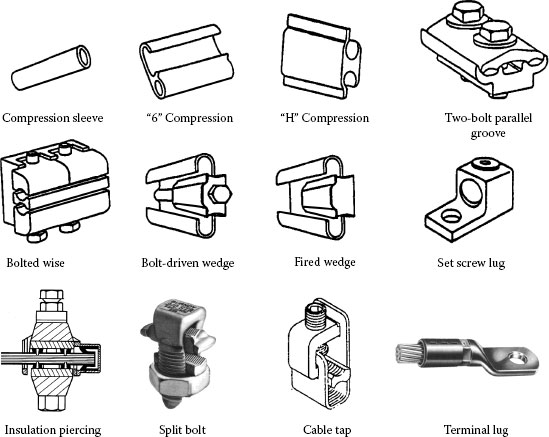
FIGURE 5.1
The generic connector designs commonly used on power network.
It is generally accepted that a good mechanical joint is also a good electric joint. In many cases, this may not be so owing to the intrinsic nature of current transfer across the contacting members, and also the design features of a particular connection and deterioration mechanisms that may impact on the connection performance. Hence, it is of importance to review the basic design characteristics of the most common types of power connections and the factors that influence their performance since only with proper attention to these factors can a good electrical connection be made consistently. Connectors can be broadly classified into three groups: light-, medium-, and heavy-duty connectors according to their current-carrying capacity and their functional operation.
1. Light-duty connectors are devices carrying very low flows (below 5 A), operating at voltages up to 250 V. The successful operation of these devices depends mainly on maintaining relatively low and stable contact resistance, and also on the selection of the contact materials. This type of connector is discussed in Chapter 6.
2. Medium-duty connectors are those carrying appreciably higher currents (above 5 A), and operating at voltages up to 1,000 V. For this group electrical wear becomes of prime importance. The factors governing contact material selection to meet the very severe operating conditions are tendency to welding, material transfer and erosion (pitting). Applications of this group are control devices for industrial, domestic and distribution network applications.
3. Heavy-duty connectors carry very high currents (up to tens of kA) and operate at very high voltages (up to hundreds of kV). These are mostly found in electrical distribution and transmission systems.
The connectors can also be classified according to their applications:
5.2.1 Plug-and-Socket Connectors
This type of connector is intended for quick electrical engagement and disengagement of electrical or electronic units. The most important requirement imposed on this type of connector is the maintenance of satisfactory operation when operative or inoperative over various periods of time. Plug-and-socket connectors basically comprise contact base and contact-finish materials. Material selection for these devices is based on electrical (conductivity), mechanical (rigidity, flexibility) and contact force deflection characteristics, and on contact design. There is a wide variety of the plug-and-socket types of connector, the most common being jacks, pins, rack and panel connectors, IC sockets, printed-circuit edge connectors and terminal boards (See Chapter 6, Sections 6.2 and 6.3).
These are devices intended for connecting wires and cables to connection points of electrical equipment. In general, wire connectors can be permanent such as welded, crimped or thermo compression bonds; or semi-permanent such as soldered, wrapped or screwed joints. The most commonly used are lugs, crimps, splices, compression-screw lugs, set screws, binding-head screw terminals, eyelets, clamp-on types, split-bolt types, and straight-coupling types.
Since bolted and compression connections are widely used on the power network, this chapter will focus on some basic feature of these connections, degradation mechanisms affecting their performance, palliative measures used to suppress the adverse effects of the contact deterioration, installation practices, testing methods and also recent developments in connector materials and design.
5.2.4 Insulation Piercing Connectors
Insulation piercing connectors are designed to operate with hermetically-sealed electrical contacts to prevent moisture ingress. After installation, the perforated insulator on the conductor presses on the sides of connector teeth with sufficient force to prevent ingress of harmful environmental contaminants through the perforations. The shape and number of teeth on the jaw are designed to optimize the grip on the conductors.
5.3 Properties of Conductor and Connector Materials
5.3.1 Definition of Conductor and Connector Systems
A conductor system is defined as an assembly comprising the current-carrying member (conductor), insulation, protection, shielding and termination. The current-carrying member is normally a solid wire or a combination of wires (strands) not insulated from one another. A cable on the other hand is a stranded conductor or a combination of conductors insulated from one another. The main function of the current-carrying member is to yield an uninterrupted passage of electrical current through the system, and the insulation serves to restrain the current flow in the system to the conductors. The protective function of the conductor system isolates the current-carrying member from external influences. The basic function of shielding is to reduce the effect of electric and magnetic fields on the cable.
A connector serves to provide connection between electrical circuits, to carry the current for the required period without overheating. The execution of a connector is defined by the following factors: tendency to oxidation (tarnishing), welding, and corrosion; hardness; melting point; resistance to wear and friction; electrical and thermal conductivity; and also by the operating conditions such as interrupting voltage, current to be carried, contact pressure, contact size, frequency of operation, and rapidity of interruption. The most significant feature of a connector is the contact resistance. There are a number of factors affecting the contact resistance; for example, mechanical, physical, and electrical properties of the connector materials, the tendency of the contact material to oxidation, contact pressure and contact area, see Chapter 1.
In ordinary engineering usage, a solid conductor is a material of high conductivity. The electrical conductivity of metallic conductors is of the order of 106–108 S/m at ambient temperature (see, for example, Table 24.1C). Solid metallic conductors can be generally classified into two groups according to their applications:
• Pure metals, the most common and widely used of which are Cu and Al, sometimes alloyed with other metals to improve their mechanical properties; and
• Alloys, used as conductors with particular properties such as wear resistance, magnetic properties and friction, the most common materials being bronzes, brasses and some aluminum alloys.
Practical application of solid metallic conductors requires a detailed knowledge of various properties of conductor materials, such as electrical, thermal physical, chemical, mechanical and tribological characteristics, because in service, solid conductors are subjected to various mechanical and thermal stresses and also environmental effects.
5.3.2 Factors Affecting Conductivity
Modern electron theory of metals asserts that conduction is to be understood in terms of the effective number of free electrons and the mean free path of those electrons. It is the large number of free electrons which makes elements such as silver, copper and aluminum good conductors. On the other hand, for a given conductor, the deleterious effects on conductivity imparted by alloying, plastic deformation, structural defects and heating result from a reduction of the mean free path of the electrons. Contributions to the resistivity coming from the sources of electron scattering are additive. This is known as Matthiessen’s rule, which can be summarized as
(5.1) |
where ρi is a temperature-dependent term reflecting the thermal vibration of the lattice ions and is known variously as the “ideal,” intrinsic, lattice or phonon resistivity; ρo usually called the “residual” resistivity, arises from electron scattering by the lattice imperfections, and is generally independent of temperature.
Although the rule gives good agreement with experimental data, especially at higher temperatures, there is increasing evidence that it is not strictly valid and that deviations are to be expected at lower temperatures. The nature of these deviations depends on the type of impurity atoms or other defects present as well as on their quantity; this is particularly evident when transition metal impurity atoms are present. Deviations from Matthiessen’s rule found experimentally may be generally expressed as a temperature-dependent measure.
Over the moderate temperature range of most common service operations, such as 0°C–150°C, the properties of conductor materials vary linearly with temperature. The changes in conductivity or resistivity and also physical dimensions with temperature are appreciable and should be taken into account in many engineering calculations. In the case of linear conductors these changes can be expressed as:
(5.2) |
(5.3) |
where RT and lT are respectively the resistance and length of a conductor material at some temperature T; Ro and lo are the resistance and length at 20°C and αR and αL are respectively the coefficients of electrical resistance and linear expansion (See Tables 24.1B and 24.1C).
5.3.2.2 Effect of Lattice Imperfections
The effect of lattice imperfections on the resistivity of a pure metal manifests itself through an increase in the residual resistivity ρ0 which is very sensitive to the presence of imperfections in the lattice. In studying the effects of imperfections, to minimize the effects of thermal vibrations (phonon scattering), electrical resistivity measurements are usually carried out at very low temperatures, where the thermal part of the resistivity may be considered negligible. In this instance, at low defect concentrations, the residual resistivity increases with the concentration of defects since the interferences among the defects themselves can be overlooked. The change in the residual resistivity is then an appropriate measure of the defect concentration in the metal.
(a) Impurities and solutes. The presence of impurities or solutes (alloying additions) in the lattice decreases of the conductivity of a conductor much more than any other lattice imperfection. The extent of the reduction depends on the type, concentration and the metallurgical state in which the impurities are present. The impurities are more effective in reducing the conductivity when present in solid solution than as, or incorporated in, a second phase of the microstructure. This is understandable, since disturbances of the lattice periodicity on an atomic scale, as produced by impurities in solid solution, more effectively increase the electrical resistance than perturbations on a macro scale caused by the presence of a second phase. Within the solubility limit of a particular impurity there is a linear relationship between the concentration of this impurity and the increase in electrical resistivity. It is clear that purity of solid conductors is of prime importance for electrical purposes. However, producing high-purity conductor materials involves higher processing costs, perhaps not be economical for practical use. Increasing the purity of conductor materials weakens them mechanically. Therefore deliberate addition of a particular solute or solutes in limited amounts may considerably improve a conductor’s the mechanical response without degrading its conductivity.
(b) Deformation dislocations. Plastic deformation of a metal tends in general to harden it, reduce its ductility and increase its tensile strength and electrical resistivity. The increase in tensile strength is useful and thus many types of conductors are finished by cold working. All or at least an appreciable fraction of the increase in electrical resistivity is caused by the scattering of conduction electrons by dislocations introduced into the lattice by plastic deformation. Broadly speaking, the resistance increase Δρ owing to plastic strain γ is given as
(5.4) |
where a and n are constants characteristic of a particular conductor material. Annealing of a plastically deformed conductor reduces electrical resistance and tensile strength but increases ductility.
(c) Vacancies. An appreciable concentration of vacancies can be made in a solid conductor by rapid quenching from an elevated temperature and also by irradiation with high-energy particles. The effect of vacancies produced in this way on the electrical resistivity is more pronounced in very pure metals, since in less pure metals both the number of vacancies created and their resistance contributions are affected by the solute.
(d) Grain boundaries. In an ideally pure metal, the contribution to the resistivity owing to the grain boundaries arises from the electron scattering at these boundaries. An electron crossing the boundary enters a region where it cannot continue in the same direction and with the same velocity. This is owing to the anisotropy of elastic and electronic properties of the solid in the grain boundary region. With advances in microelectronics, considerable attention has recently been given to the gist of the grain boundaries on electrical conductivity of thin solid films, not only at lower but also at higher temperatures. This is because it has been found that the grain boundaries and also the segregated alloy or impurity species at the grain boundaries can significantly affect the performance and transport properties of thin, solid film conductors.
When a magnetic field applied in the same direction as the electric field causes a current to flow through a specimen, the conduction electrons are constrained to follow helical instead of linear paths between collisions. Because of this effect, the impedance is usually higher than that obtained in the absence of a magnetic field. The fractional change in resistance that occurs is called longitudinal magneto resistance. On the other hand, application of the external magnetic field in a transverse direction to the electric field results in a different current density parallel to the applied electric field. The fractional change in resistance that occurs is called transverse magneto resistance. In addition, a potential gradient is made perpendicular to both the applied magnetic and electric fields, resulting in the phenomenon called the Hall Effect.
Except in certain ferromagnetic metals and alloys, longitudinal and transverse magneto resistances are positive, that is, the electrical resistance increases with increasing magnetic field strength. In the case of ferromagnetic materials, iron for instance, resistivity, particularly at low temperatures, initially decreases, reaches a minimum value and then gradually increases as the field strength increases. Such behavior of the magneto resistance at lower fields is associated with changes in magnetic domain configurations, but the detailed electron scattering mechanism is not fully understood. The relative magnitude of the resistivity change Δρ owing to the magnetic field usually increases with purity. This rule holds well for most metals, but there are some exceptions, such as high-purity aluminum, for which the magneto resistivity tends towards a saturation value.
The conductivity of a solid conductor when an alternating current field is applied is controlled at higher frequencies by the phenomenon called the skin effect. This is an electro-dynamic effect arising from the way in which the time-varying electric and magnetic fields and electric current are interrelated. The distribution of the current in a specimen is nonuniform; for example, a 50 or 60 Hz alternating current flows mainly in a 10 mm layer at the surface of the conductor. It is important for nonmagnetic materials such as copper or aluminum, the magnetic permeability of which is 1, so that the increase in AC resistance at higher frequency is entirely owing to the increase in the frequency of the passing AC current. In the ferromagnetic materials, the conduction is characterized by numerous unusual features arising from the presence of magnetic ions in a conductor influencing the resistivity, regardless of the external field.
Generally speaking, a conductor consists of a solid wire or an assembly of wires stranded together and used either bare or insulated. In this article, only bare conductors will be considered. The most extensively used materials for electrical conductors are copper and aluminum. The basic properties and applications of these materials are summarized in Table 5.1.
5.3.3.1 Copper and Copper Alloys
Copper is a soft, malleable and ductile metal with high conductivity and excellent weld-ability and solderability. By rolling and drawing, a variety of electrical products such as wires, sheets, tubes, shaped bars, and flat busbars can be manufactured. The high-conductivity copper useful for electrical applications must be brought about by careful refining treatments such as electrolytic refining which removes Ag, Au, As, Sb and other impurities. The most common copper used in the power industry is electrolytically tough pitch copper ETP or C11000 made by electrolytic refining of copper. The main shortcoming of ETP copper is the embrittlement to which it is subject when heated in hydrogen to temperatures of 370°C or more. This results from the presence of oxygen in the metal which reacts with the hydrogen, making steam and leading to internal cracking. The solution to this problem is to use copper of substantially lower oxygen content. While phosphorus is an effective deoxidizer for copper, it degrades the conductivity too much to give a product suited for electrical applications. Instead, electrolytic slabs are melted and refined in a special process using oxygen-free inert gas and no metallic oxidizers. The result, a 99.98% pure copper with essentially no oxygen and <0.005% of any one impurity, is known as oxygen-free high-conductivity copper (OFHC). The conductivity of copper is frequently referred to in terms of the international annealed copper standard (IACS), thus % IACS equals 100 (resistivity IACS/resistivity of sample). In absolute terms, the IACS has resistivity of 1.7241 μΩ cm. A common criterion for defining the purity of metals is the ratio of their resistivity at 273 and 5.2 K. This ratio varies between 150 and 400 for OFHC copper but can reach 1000–5000 and higher for zone-refined materials.
TABLE 5.1
Selected Properties of Copper and Aluminum Conductors
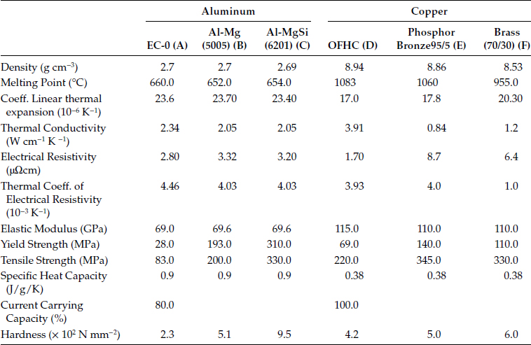
A—Annealed;
B—0.8% Mg Fully cold worked (H19);
C—0.7% Si—0.8% Mg, Solution treated Cold worked, Aged (T81);
D—Annealed, grains size 0.05 mm;
E—94.8% Cu-5% Sn-0.2% P, Annealed, grain size 0.035 mm;
F—70% Cu-30% Zn, Annealed.
Under normal atmospheric conditions, copper is comparatively resistant to corrosion. At room temperature, an oxide layer, Cu2O, forms which protects the surface from further oxidation and is a semiconductor. At higher temperatures as a result of exposure to air, a CuO oxide layer is formed. Considerable corrosion of copper may be produced by air containing ammonia or chlorine compounds. The use of copper near the sea coast is undesirable, since the salts present in the air can cause severe corrosion. Moist atmospheres containing sulfur dioxide attack copper, resulting in the formation of a mixed oxide sulfide scale. For electrical applications, the mechanical properties of copper have to be improved, but in doing so the electrical conductivity is often reduced. Strengthening can be achieved by cold working and/or alloying copper with various elements. Cold-drawn pure copper can be softened by annealing at 200°C–325°C, but previous cold deformation and the presence of impurities can alter this annealing range. The higher the level of prior cold deformation, the lower is the range of annealing temperature, whereas the presence of impurities or addition of various elements raises the annealing temperature.
The amount of silver added is in the range 0.030–0.1% and results in improved creep strength and resistance to softening at elevated temperatures without appreciable sacrifice of electrical conductivity. This alloy is commonly used for current collectors of electrical machines.
This contains 0.5–2% Be as the principal alloying element, but Ni and Co are also often added so as to achieve desirable properties. It is nonmagnetic and has excellent mechanical (elastic) properties. Its primary application is for springs, diaphragms, switch parts and electrical connectors. The precipitation hardening alloy is heat-treated by annealing at 900°C followed by water quenching and subsequent aging at 425°C.
This alloy contains 0.0~1.0% Cd and has excellent capacity for cold working and hot forming and also for soldering, brazing and gas-shielded arc welding. It is widely applied in fine wire applications for airplane electric circuitry, as well as in commutators segments and other applications.
The total amount of Cd and Sn may reach 2%. The primary applications are for telephone lines, electric motor brushes, and parts for switching devices.
The Cr concentration is in the range 0.150.9%. This precipitation-hardened alloy has a large part of the solute contained in the second phase, which imparts excellent mechanical resistance at higher temperatures. Its main applications include electrode materials for welding machines, heavy duty electric motors and circuit breaker components, switch contacts, current-carrying arms and shafts and electrical and thermal conductors requiring more force than is provided by unalloyed copper.
The amount of tellurium added is 0.30.7%, to improve machinability while retaining ~90% IACS. This alloy also has excellent solderability and corrosion resistance. It can also be applied at relatively high temperatures. Typical uses include electrical connectors and motor and switch parts.
This contains 0.1–0.2% Zr. Because of its low tendency to embrittlement and improved creep behavior at higher temperatures and mechanical stresses, it is used for switches and circuit breakers for high-temperature and high-vibration service, commutators and studs and bases for power transmitters and rectifiers.
This class of copper encompasses high Cu-Sn alloys. The tin concentration ranges from 5% to 15%. All bronzes have superior mechanical properties but inferior electrical properties relative to copper. The electrical resistivity of bronze can be 2–20 times that of electrolytic copper. Bronzes are frequently ternary or quaternary alloys containing third elements such asp. Si, Mn, Zn, Al, Cd or Ni; the third element is normally expressed in the name of the alloy. Bronzes for electrical applications contain less tin and other metals than bronzes for structural applications, for which mechanical properties and corrosion resistance are determining factors. Typical applications of the bronzes are springs, diaphragms, bushings, face plates, connectors, and electrical machinery parts.
These are alloys containing nominally 15–40% Zn. Addition of other metals such as Mn Ni and Al improves their mechanical strength. Brasses are seldom used for electrical conductors, owing to their low conductivity. Typical electrical uses are conduits, screw shells, sockets and receptacle contact plates where formability is an important consideration. When using some types of brass intended for mechanical or structural applications, care should be taken to avoid dezincification and stress-corrosion cracking (See Section 2.4.3.4), which occur under certain conditions.
5.3.3.2 Aluminum and Its Alloys
In recent years, for a number of economic and engineering reasons, aluminum has gained an ever-increasing application, Because of its light weight, relatively good electrical and thermal properties, availability and moderate cost, aluminum is being seen as a viable alternative to copper for many conductor applications in electrical systems. In substituting aluminum for copper, however, due account should be taken of their differences in resistivity, mechanical strength and density. For the same resistance and length, an aluminum conductor should have a cross-sectional area 60% larger than that of an equivalent copper conductor, whereas the weight of the aluminum conductor is 48% of that of the copper conductor. The current-carrying capacity of aluminum is 80% of that of copper. Aluminum is a ductile metal with relatively high thermal and electrical conductivity. It is softer than copper and can be rolled into thin foils several μm thick. However, because of its low mechanical strength, aluminum cannot be drawn into very fine wires. The resistivity and mechanical durability of aluminum depend on its purity and grade of cold work. By selecting the proper fabrication process, aluminum containing 10 ppm of impurities can be obtained with a resistivity ratio surpassing 1,000. Higher resistivity ratios, >30,000, can be obtained by zone melting.
The resistivity of high-purity aluminum (99.999%) is 2.635 μΩ cm at 20°C, whereas that of the commercial grade is in the region of 2.78 μΩ cm. The commercial grade aluminum contains nominally <0.1% Si and <0.015% (Mn, Ti, Cr. V). To minimize further, the effect of the impurities (Ti and V in particular) on the conductivity of the aluminum, 0.02% boron is often added, leading to the transformation of these impurities (except Mn) into borides that have very little effect on electrical conductivity, as they are not in the dissolved phase. Pure aluminum, even if hard-drawn, possesses inadequate mechanical properties. This shortcoming can be somewhat overcome by alloying with a variety of other metals, resulting in improved tensile and creep strengths. The alloys most frequently used for electrical applications are Al–Mg or Al–Mg–Si also containing Fe or Co.
Broadly speaking, there are three main categories of application of aluminum and its alloys. These are overhead transmission lines and underground cables, coil winding (magnet wire) and busbar conductors. For overhead transmission lines, the aluminum alloy used generally contains 0.8% Mg or 0.5% MgSi and has high strength combined with relatively good electrical conductivity. However, the mechanical strength of this alloy may not always be sufficient, for example, for long spans in overhead lines, in that case, conductors of composite construction are used, in which the core of the line is composed of steel wires. Alloys for coiled winding wire (magnet wire) have a relatively high concentration of Fe and a low Si content. This ensures rather high elongation values for the wire in the annealed condition, a higher recrystallization temperature and a higher tensile strength at elevated temperatures. Further improvements in the mechanical strength of these alloys can be achieved by adding small amounts of Mg or Cu. The use of aluminum alloys for coil winding wires requires some design alterations: motors and transformers have to have larger slots to accommodate the larger gauge size of the aluminum wire if this is to have the same conductance as copper magnet wire.
For busbar, Al–Mg–Si alloys are mainly used, because of their excellent corrosion resistance and their good workability and electrical and mechanical properties. When jointing the busbars, care must be taken in order to minimize the effect of stress relaxation (See Section 5.4.14). One of the most important drawbacks that prevent even wider use of aluminium as a conductive material is the lack of a truly reliable and economic method of termination. To overcome this problem many methods such as welding, plating, ultrasonic bonding, plasma spraying, bolting, clamping, and brazing have been adopted, but most of them are relatively expensive and require greater operator care; in some cases they are marginal in electrical or mechanical operation.
5.3.4 Materials for Connector Systems
5.3.4.1 Pure Metals and Alloys
Pure metals and alloys in this group are used as plating materials for copper and aluminium substrates.
It is widely used as plating or coating material for the contact parts of the connectors (See also Chapter 8). The main drawbacks of silver are low melting and boiling points, low mechanical strength, possible contact welding, and a tendency to form sulfide films (tarnishing). Other problems with silver are whisker growth and the diffusion of silver atoms through certain electrical insulation materials, such as phenolic fiber, under the influence of applied electrical fields, which may cause failure of the insulation to occur (See Chapters 2 and 8). Improved mechanical properties and a higher resistance to tarnishing may be achieved by alloying with copper, cadmium, gold, palladium or platinum. The addition of copper decreases the electrical conductivity, resistance to oxidation and corrosion, melting point and cost, but increases hardness. Small amounts of nickel (0.2–3%) improve the wear rate and decrease the chance of welding and tarnishing. The addition of cadmium (~5%) decreases the electrical conductivity, melting point and oxidation resistance, but improves the resistance to tarnishing. The additions of platinum, palladium, or gold all harden silver, decrease the electrical conductivity and improve the resistance to wear, tarnishing, and metal transfer.
Copper and its alloys have been described in the previous section. It is sometimes used as a plating material.
Platinum has exceptional resistance to tarnishing, oxidation and corrosion. It is suitable for light-duty applications where operating currents are below 2 A, contact-pressure is low and where reliability is the most important parameter. However, under fretting conditions, platinum contacts are susceptible to frictional polymerization. Additions of iridium, ruthenium, and osmium to form binary or ternary alloys increase hardness, mechanical strength, melting point, resistivity, and wear resistance.
Palladium has a lower resistance to corrosion, oxidation, and tarnishing than platinum. It begins to tarnish at 350°C but the tarnish film formed decomposes at 900°C. The additions of copper, ruthenium, silver, or combinations of other metals improve the mechanical properties of palladium with some decrease in corrosion resistance, and lower cost. In atmospheres containing traces of organic compounds, palladium contacts subjected to motion relative to each other (fretting) tend to form an insulating frictional polymer.
Gold has an excellent tarnish and oxidation resistance, but is very soft and susceptible to mechanical wear, metal transfer and welding. It is widely applied in computers and telecommunication and data transmission devices where operating currents are not more than 0.5 A. The addition of copper, silver, palladium, or platinum, forming binary and ternary alloys, improves the hardness without loss of tarnish resistance, but usage is restricted to low-current applications. Hard gold contains a low percentage of nickel or cobalt (See Chapter 8).
Rhodium is also very resistant to tarnishing, but is very strong and extremely useful as a contact material. Nevertheless, owing to difficult fabrication it is used solely as a plating material in light-duty electrical contacts where reliability is of the utmost importance.
Tungsten is a very hard metal with excellent resistance to wear, welding, and material transfer, with high melting and boiling points. Its main disadvantages are low corrosion and oxidation resistance, high electrical resistivity and poor formability. Tungsten for contact applications is generally combined with silver made by powder metallurgical processes (See Chapter 16).
Even though nickel forms a protective oxide film, it and its alloys are suitable for a wide variety of applications, the majority of which involve corrosion and/or heat resistance. It is widely used in as a plated substrate for other metal platings such as tin, silver and gold. Other applications require low-expansion, electrical resistance, soft magnetic and shape-memory nickel-base alloys. When used in a clad composite with copper, it can provide composite with a very well controlled-expansion characteristics. The low expansion of Invar with other alloys of different expansion can provide a series of thermomechanical control and switchgear devices. The electrical resistance nickel alloys are commonly used in instrumentation and control equipment to measure and regulate electrical characteristics or to generate heat in furnaces and appliances. The most common alloys in this form of alloys are Cu–Ni (2–45% Ni), Ni–Cr–Al (35–95% Ni) and Ni–Cr–Si (70–80% Ni). The permeability properties of soft magnetic nickel-iron alloys are used in switchgear and direct current motor and generator designs. The lower-nickel alloys (<50% Ni) with a fairly constant permeability over a narrow range of flux densities are primarily used in the rotors, armatures and low level transformers. High-nickel alloys (~77% Ni) are used for applications in which power requirements must be minimized such as transformers, inductors, magnetic amplifiers and shields, memory storage devices and tape recorder heads.
5.3.5 Electroplating and Cladding
Electroplating and cladding are common methods of covering large contact surfaces (See also Chapter 8). The most common and widely used plating materials are silver, gold, tin, and nickel. Base materials commonly used as the current-carrying member of a connector, such as copper and its alloys, can readily be plated with any of these plating materials. Tin has also come to be considered as a suitable substitute for gold plating on electrical connectors used in low-voltage low-current operations. Nevertheless, the primary applications of tin in the electronic and electrical industries are either as solders or coatings to aid soldering or improve the connectability of wires and cables with the electrical equipment. Tin coatings are soft and ductile, and with a thick coating soldering can easily be done. However, owing to its low hardness and tendency to oxidize readily to yield a self-healing film, tin is less satisfactory as a contact finish material.
According to the available data, nickel appears to be the most practical coating material from the point of view both of its cost and the significant improvements to the metallurgical and contact properties of electrical connectors. The resistance of nickel to form intermetallic phases with copper, aluminum, and other metals, makes it as a very effective diffusion barrier in a variety of electrical and electronic devices where diffusion between the coating and substrate base represents a significant problem. In recent years, nickel was successfully employed for coating aluminum conductors and power connectors. However, nickel does not protect aluminum galvanically and presents subsurface corrosion problems when plated over aluminum. Furthermore, fretting produces considerable degradation of the contact zones in nickel-coated aluminum contacts. Lubrication and higher loads are found to mitigate these adverse effects. Despite these disadvantages, nickel-plating is still becoming more attractive for contact applications in electric power applications.
Cladding of common base metals (such as copper and its alloys [brass, bronze], steel, and aluminum) with precious metals such as gold and silver in order to obtain the optimum combination of functional properties is now a well-established technique. Cladding permits properties such as thermal and/or electrical conductivity, high strength, corrosion wear and high temperature resistance, weldability, light weight and springiness to be merged. Cladding can be done in the form of inlays, toplays, overlays and edge lays. Typical applications of clad metals include contacts, thermostats, blades, springs, contact brackets, bonding pads, lead frames and connectors.
5.4 Parameters Affecting Performance of Power Connections
The widespread use of aluminium in a variety of electrical applications has prompted numerous studies into the processes occurring in aluminium connections. Published experimental evidence suggests that reliable aluminium connections cannot be obtained by the routine application of the practices and methods established for joints with copper conductors. The problems with interfacing aluminium derive from the fact that whenever two dissimilar metals are brought together, the differences in their physical, mechanical and metallurgical properties as well as the manner in which they react under specific conditions determine their level of compatibility. The primary purpose of an electrical connection is to allow uninterrupted passage of electrical current across the contact interface, which can only be achieved if a good metal-to-metal contact is made and maintained. However, in the case of aluminum connectors, this requirement cannot always be met owing to the ever-present insulating oxide layer at the surface, the propensity to undergo creep and stress relaxation, the susceptibility to galvanic corrosion, and the large thermal expansion coefficient, which may lead to fretting at the contacting interfaces. This situation can result in failure of a connection. The complexity of failure mechanisms in aluminum power connections is best depicted in the course of a cycle, as shown in Figure 5.2. These concerns will be discussed later in this chapter.
5.4.1 Factors Affecting Reliability of Power Connections
Reliability is most commonly defined as the probability of equipment or a process to function without failure, when operated correctly, for a given period of time, under stated conditions. Anything out of that is a failure. One of the most significant problems in providing reliability to electrical contact is the discrete nature of the interface. An electrical contact between slides is formed in discrete regions within the contacting interface and these areas (a-spots) are the only current conducting paths (See Chapter 1). The formation of the real and conductive contact areas controls the reliability and efficiency of the electrical contact. These processes depend on a great number of independent or interrelated factors. The variety of the factors can be conventionally divided into the performance factors governed by the operating conditions and the design-technological factors determined by the fabrication characteristics of a contact unit. The performance factors (parameters) are divided basically into two groups: internal and external (Figure 5.3). Figure 5.4 shows schematically the influence of the design-technological factors on the reliability and quality of electrical contacts. The selected kind of contact materials, the contact geometry, the intermediate layers separating the contacting surfaces, the quality of the deposited coatings and the contact surface microrelief determine the apparent contact area, the size, number, and distribution of contact spots. This, in its turn, influences the real and electrical contact areas, the constriction and surface film resistances, and, lastly, the electrical contact reliability. The internal factors are the mechanical (the contact load, the type and characteristics of motion such as case, the sliding velocity, and reciprocation) and electric (type and strength of current, operating voltages) factors.
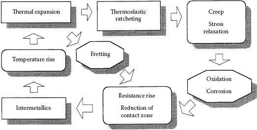
FIGURE 5.2
Schematic of degradation mechanisms in aluminum connections.
The external factors may be temperature-time variation, humidity, atmospheric pressure, effect of aerosols etc. and these are often uncontrollable. The performance factors affect the properties of contact materials and surface films, the occurrence of physical and chemical processes in the contact zone, wear particle formation thus influencing the state of the interface and, finally, the contact resistance and reliability of electrical contacts
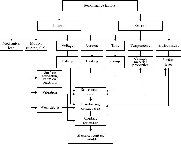
FIGURE 5.3
Effect of performance factors on the reliability of electrical contacts.
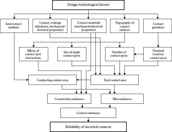
FIGURE 5.4
Effect of design-technological factors on the performance of electrical contacts.
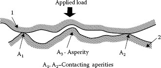
FIGURE 5.5
Contacting asperities.
It has been established [1,2] and presented in Chapter 1 that real surface is not flat but comprises many asperities (Figure 5.5). Hence, when contact is made between two metals, surface asperities of the contacting members will penetrate the natural oxide and other surface contaminant films, establishing localized metallic contacts and, thus, conducting paths. As the force increases, the number and the area of these small metal-metal contact spots will increase as a result of the rupturing of the oxide film and extrusion of metal through the ruptures [3,4,5]. The real contact area Ar is only a fraction of the apparent contact area Aa, as illustrated in Figure 5.6. The relationship between the applied normal load Fc, hardness of the metal H and the apparent contact area Aa is given by the following expression
(5.5) |
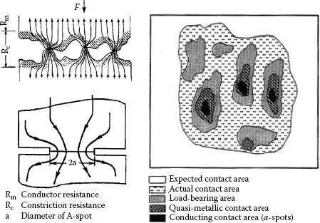
FIGURE 5.6
Schematic of current constriction and real contact area.
TABLE 5.2
Effect of Normal Load on Real Area of Contact for Clean Surfaces
|
Real Contact Area/Apparent Contact Area (Ar/Aa) (%) |
||
Alloy/Applied Load |
10 N |
100 N |
1000 N |
Al (H-19) |
0.01 |
0.1 |
1.0 |
Al (H-0) |
0.05 |
0.5 |
5.0 |
Al + 0.75% Mg + 0.15% Fe (H-19) |
0.01 |
0.1 |
1.0 |
Al + 0.75% Mg + 0.15% Fe (H-0) |
0.02 |
0.2 |
2.0 |
Cu (H-0) |
0.008 |
0.08 |
0.8 |
(H-0)—Fully annealed;
(H-19)—Fully hardened.
on the amount of deformation of the asperities and is equal to 1 in most practical contact systems. On the other hand, Holm [1] has shown that the hardness (H) is related to the yield stress (σy) by the following expression:
(5.6) |
The results, shown in Table 5.2 show the real contact area as a percentage of the apparent contact area Aa at various normal loads. It should be noted, however, that the real contact area calculated in this manner includes the load-bearing area which can be covered with the oxide film and is not, therefore, a dependable path for transfer of electrical current. Hence, the conducting contact area will be a fraction of the calculated real contact area. Current passing across a contact interface is therefore constructed to flow through these a-spots. The electrical resistance of the contact owing to this constricted flow of current is called “constriction resistance.” Since the metals are not clean, the passage of electric current may be affected by thin oxide, sulfide and other inorganic films usually present on metal surfaces, the total resistance of a joint (Rab) is then a sum of the constriction resistance (Rc), the resistance of the film (Rf) and the bulk resistance (Rb)
(5.7) |
,
film thickness
Rb = Bulk resistance
ρ = resistivity of the contacting asperity material
n = number of contacting asperities
σf = Film conductivity
In most practical applications, the contribution of these films to the total contact resistance is of minor importance, since the contact spots are usually created by the mechanical rupture of surface films. Both tunnelling and fritting are also considered as operative mechanisms for the current transfer across the film. Figure 5.7a illustrates schematically the current transfer across the contact interface whereas in Figure 5.7b is shown variation of the contact resistance with applied contact load. It should be pointed out that the electrical interface of an a-spot is far different from the single circular contact spot. In fact, the true metal-to-metal contact is limited to a cluster of microspots, within the nominal contact spot, where the contacting materials extrude to touch each other through cracks in their oxide film as demonstrated by Williamson in the case of aluminum connections [3].
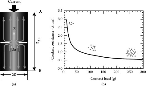
FIGURE 5.7
(a) Schematic of current transfer across the contact interface and (b) Contact resistance variation with applied contact load.
The effect of current density variations in power contacts has been investigated by Malucci [4]. The Greenwood approach to estimating the interaction between current carrying contact spots was used to study the degradation of individual spots. The degradation is assumed to occur from electro-migration which causes a non-uniform increase in the effective resistivity across each contact spot. The latter results were used to assess the degradation of a simulated multi-point interface to demonstrate the cascade failure mode believed to come in power contacts. In addition, factors such as spot size, position and interaction with nearby spots were assessed in their impact on current density variation across the contact region. Figure 5.8 shows the random array cascading degradation of the power connection interface.
Joint resistance of copper–copper busbar joints as a function of contact load at 105°C was investigated by Schlegel et al. [6]. It was demonstrated that in pure copper joints the ageing mechanism of joint force reduction is determined by different physical mechanisms: setting process, dynamic recovery, dynamic primary recrystallisation, and grain coarsening (secondary recrystallisation). The acting mechanisms depend on time, temperature, grain size at initial conditions, the degree of cold work and foreign particles. The result of the long-term tests showed that the force reduction is critical at temperatures ≥140°C in joint systems with washers and material compositions allowing large deforming degrees of the Cu-ETP. For Cu-ETP the material condition having higher mechanical properties at initial state showed a worse long-term behavior. For practical applications at high temperatures it is recommended to use the less cold-deformed material.
For power connectors where the contact force is much higher than a few Newtons plastic deformation of asperities that form the a-spots occurs. As indicated in Chapter 1 if the film resistance is ignored, the constriction resistance will be:
(5.8) |
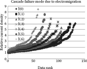
FIGURE 5.8
Random array cascading degradation.
For very light contact forces that are presented in Chapter 12, the deformation of the asperities is an elastic deformation. This gives a constriction resistance proportional to the (1/3) the power of the applied load (F) and sphere radius (d) if all elastic deformation is assumed.
(5.9) |
There can be regions of contact force where both regimes combine [7,8].
In the case of plated contacts, when the plating thickness is comparable to the a-spot diameter, plating introduces an additional component to the contact resistance. This is because the constriction lies partly in the plating and partly in the bulk conductor. As a result, the current flow is diffracted as it crosses the boundary, as schematically illustrated in Figure 5.9 [5]. Electrically conductive coatings produced by electroplating reduce the contact resistance owing to, among other factors, decrease in hardness, higher conductivity of plating compared to the substrate, prevention of insulating film formation, corrosion, reduction in mechanical wear, etc. In case of conductive plating, the electrical resistance depends on the relation between the coating thickness and the a-spot diameter as well as in the ratio of conductivities of plating and substrate. Figure 5.10 depicts the current distribution in the metal surface film when the film conductivity is smaller than that of the substrate and a-spot radius is more or less the same size as the film thickness. If the resistivity of the plating is larger than that of the substrate and the a-spot radius is close to the film thickness, the electrical current from the a-spot spreads out easier into the substrate than into the plating. The potential drop in the vicinity of the a-spot in the substrate is negligible in comparison with the potential drop across the film [1]. Williamson [3] has shown that the constriction resistance of a single copper conductor with current flowing through a single contact spot is increased by a factor of five if the conductor is plated with a layer of tin as thick as the contact spot radius.
(5.10) |
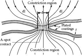
FIGURE 5.9
Schematic of formation of a-spot between plated surfaces.
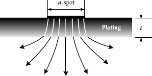
FIGURE 5.10
Current distributions in metal surface film when the film conductivity is smaller than that of the substrate and a-spot radius is of the same size as the film thickness.
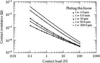
FIGURE 5.11
Contact resistance variation of tin-plated contact with applied load and plating thickness and ξ = 1.0.
If a-spot radius and the plating thickness do not differ greatly, the spreading resistance increases approximately linearly with plating thickness. For relatively thick film, the spreading resistance deviates from the above expression and approaches . The contact resistance as a function of the applied load (F) and plating thickness (t) is shown in Figure 5.11. If the ratio the film resistance overshadows the effect of constriction resistance. From the above discussion it is clear that electrical paths of current will be fewer and the current will be distributed more uniformly if there are more contact spots. Hence, surface roughness is of great significance, since a rougher surface having many sharp asperities has a greater probability of having many metal-metal contacts and, also, the ability to penetrate its counterpart at much lower loads than a smooth surface with a consequently larger current-carrying area. Consequently, contact surfaces finished with rough abrading will have appreciably lower contact resistance than those smoothly machined [6,9]. This is clearly illustrated in Figure 5.12 schematizing the formation of a-spot on smooth and rough metallic surfaces [9,10].
When the current is confined to flow through the conducting spots (a-spots), the temperature of the point of contact (Tc) may be higher than that of the bulk (Tb). Hence, the increase in constriction resistance over the bulk resistance that can be found from Equation 5.2. In this case (Tc – Tb) is called the supertemperature and is related to the voltage drop across the contact interface (U) as follows
(5.11) |
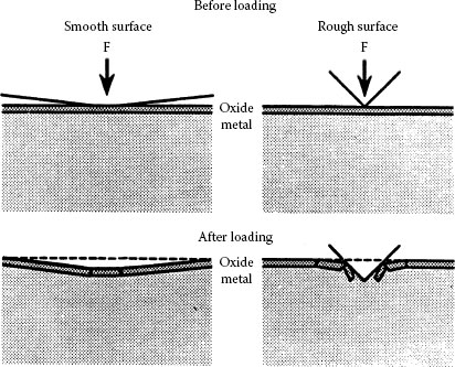
FIGURE 5.12
Schematic of a-spot formation on smooth and rough metallic surfaces.
where L is the Wiedemann-Franz Lorenz number with the value of 2.45 × 10⁻⁸ (V/K)2 [11]. It is clear that even a relatively modest increase in the contact voltage drop (U) can raise the supertemperature considerably enough to produce basic metallurgical changes such as softening or even melting of the conducting spheres. Equation 5.11 is valid under the following conditions [11]:
• Constriction is purely metallic without any interference from the oxide or contamination layers.
• Power losses owing to constriction are removed by thermal conduction.
• Current equipotential and heat equithermal flows are identical.
• Contact voltage U and temperature T are measured at points with small voltage and temperature gradients.
In a good connection, the temperature of the interface is just slightly higher than the bulk temperature but in a poor connection the supertemperature increases the bulk temperature and accelerates deterioration of the contact areas. The deterioration is cumulative resulting higher resistance, in increasingly higher temperatures and ultimate failure of the connection. In certain circumstances, such as short-circuit conditions, melting of the contact zones can occur even in well designed joints. As further deterioration occurs, these molten zones coalesce into larger areas in as the whole joint assembly becomes overheated. It might seem that the creation of welded contacts would improve the connection stability. However, on subsequent cooling and hardening, the metal contracts and cracks owing to the internal stresses set up in the process. Oxidation of the contact zones further reduces the number of available electrical conducting paths, with the result that overheating and ultimate mechanical failure of the joint occur.
The above-described scenario for contact deterioration has been questioned by Williamson [12,13] who argues that the degradation of a connector does not progress inexorably to ever-higher temperatures. Rather, it is interrupted and reversed by a phenomenon called self-healing. When a connector deteriorates and its metallic contact area becomes smaller, its supertemperature, induced by an increased current density, rises and intensifies the stresses in the joint or, more precisely, in the metallic microwelds. Although such build-up of stress tends to build a more efficient electrical connection, mechanically the accumulated stress will seek relief in the paths of least resistance, that is, in the axial direction of the joint. If the magnitude of this tension exceeds the elastic limit of the contacting members, the material yields. The contact force, maintained by the spring element of the joint, will be opposed by material with a reduced yield strength thus causing the contact area to grow. As a result, both the constriction resistance and the supertemperature will decrease. If, during softening, the metal flow fails to follow the self-healing process which causes the contact area to grow, higher temperatures will develop, resulting in the melting of the contact region. At this point the contact force pressing the conductors together will extrude the molten metal through the fissures in the contact interface and, therefore, increase the contact area and reduce the constriction resistance. The contact region cools to a lower temperature as the liquid metal freezes and the contact self-heals.
It is also important to note that the deterioration of a connector proceeds slowly at a pace determined by the nature of different processes operating in the contact zone and, likewise, in the environment. This initial stage persists for a long time without making any noticeable changes because it is an intrinsic property of clusters of a-spots that their overall constriction resistance is not sensitive to small changes in their size. However, when the contact resistance increases sufficiently to cause the local temperature to increase, a self-accelerating deterioration resulting from the interaction of thermal, chemical, mechanical and electrical processes will be triggered and the contact resistance will rise abruptly. Hence, no deterioration will be noticeable until the final stages of the connector life. This is clearly illustrated in Figure 5.13 depicting the variation of contact resistance with time for different values of current [13].
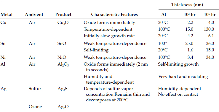
The oxidation of the metal-metal contacts within the contact interface is widely considered as the most serious degradation mechanism occurring in mechanical connectors. Oxidation is a chemical process that increases the oxygen content of a base metal and as a result, base metal or radical looses electrons. Oxidation of the metal-metal contacts within the contact interface is widely accepted as the most serious degradation mechanism occurring in mechanical connectors [10]. In the case of aluminum contacts, it is generally considered a less likely mechanism of degradation, since oxide growth is self-limiting and reaches a limiting thickness of about 10 nm within a very short period of time. This is very much less than the diameter of the contact spots, generally considered being much more than 10 nm for rough surfaces. Aluminum oxide forms as a duplex film when the bare aluminum surface is exposed to the oxygen-containing atmosphere. This duplex film consists of a very thin non-porous, inner barrier layer next to the metal with a thicker, more or less porous outer bulk layer on top. The barrier layer, which is temperature dependent, reaches a maximum thickness within microseconds, whereas the bulk film, which develops more slowly, is dependent on the relative humidity and the temperature. Up to and beyond the melting point of aluminum, the oxide formed on the metal surface remains intact and protective thus providing aluminum with a greater corrosion resistance. Oxidation kinetics of some common contact materials is presented in Table 5.3. Aluminum oxide is hard, tenacious and brittle, with a high resistivity of 1024 μΩ cm. It is also transparent so that even the bright and clean appearance of an aluminum conductor is no assurance that a low contact resistance can be achieved without appropriate surface prep. The oxide film may be broken electrically as well as mechanically. If the oxide film is thick it can be broken down by A-fritting at relatively high voltages (see Chapter 1). In electrical contacts having one or both contact members of aluminum, the current flow is restricted to flow through the areas where the oxide film is ruptured.
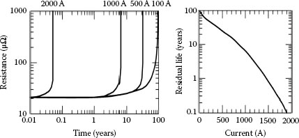
FIGURE 5.13
Variation of connector resistance with time for different values of the applied current.
In the case of copper it was shown that in the presence of oxygen-bearing atmospheres the continuous oxidation of the metal–metal contacts by oxidation can cause rapid increase in the contact resistance to a high value after remaining relatively low for a considerable length of time. The oxides of copper grow, flake, and spall off from the base metal. From about 40°C to about 200°C in air, there is a continual temperature dependent thickness growth of the Cu2O oxide. At about 200°C and above other copper oxides form while continually consuming metal. Copper oxides are softer as compared to aluminum oxides and more easily disrupted by the applied contact force. They are also semiconducting and copper contacts with an initially high resistance, due for instance to poor surface preparation, can show a steady decrease in contact resistance with time as a result of the growth of semiconducting layer over a large area. The electrical resistivity of Cu2O is 1010 μΩ cm. In the presence of a sulfur-bearing atmosphere tarnishing of the copper surface is normally observed owing to sulfide formation from hydrogen sulfide in the air. The development of tarnish film is strongly dependent on the humidity which can reduce it if a low sulfide concentration prevails or increase it if the sulfide concentration is high. The effect of humidity on the maturation of the oxide layer in aluminum is shown in Figure 5.14 [14].
TABLE 5.3
Oxidation Kinetics of Some Common Electrical Contact Materials
Campbell [15] estimated that, for an oxide film on copper in contact with gold, semiconduction would start at ~0.4 V and increase as the contact voltage rose to 1.5 V, when molten metallic junctions could be created (Figure 5.15). However, Holm [1] felt that melting was not necessary for A-fritting. The fritting voltage for a 100 nm layer of Cu2O is less than 0.0001 V, while the fritting voltage for the same thickness of Al2O3 is 40 V. New contacts can be formed by A-fritting, while B-fritting (see Chapter 1), resulting from plastic flow at a-spots, enlarges the contact area and reduces the constriction resistance. B-fritting can occur when the contact voltage required to cause metal softening (~0.1 V) is reached [1]. There have been many references in the literature to the hardness and tenacity of the Al2O3 film and to the difficulty of making a contact through this film as compared to the relative ease of forming metal-to-metal contacts in copper through a Cu2O film. Tylecote [16], however, provided many examples of cold welding of aluminum as well as of copper showing that a lower percent deformation is required to initiate welding in aluminum than in copper, and that welding is initiated at a lower deformation in cold-forged metals.
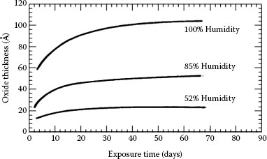
FIGURE 5.14
Effect of humidity on the oxidation kinetics of aluminum (A = 10−10 m).
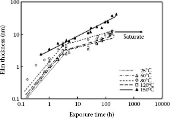
FIGURE 5.15
Growth of oxide film for exposure to elevated temperature (data of 25°C is indicated only a line).
It is commonly stated that, because annealed metals have greater ductility, plastic flow occurs more easily through fractures in the oxides of such metals, thus forming larger a-spots. It was suggested that, under plane-strain conditions, deformation was more concentrated, and cracks in the oxides were, therefore, larger, in cold-worked aluminum. Braunovic [17] showed that in high-purity aluminum (99.999% pure) and an aluminum −0.5 at. % magnesium alloy, thermal cycling caused impurities to segregate to free surfaces and affected significantly the hardness, contact resistance, and resistivity. It was suggested that vacancies, formed near the coherent metal-oxide interface, diffused into the metal and resulted in a flow of solute from the metal towards the loose surface. Auger electron spectroscopy confirmed higher magnesium content both in the oxide and at the surface in the aluminum–magnesium alloy. The solute segregation to the oxide lowered the contact resistance, but the mechanism is unknown since many other complex reactions which could affect mechanical and electrical properties (e.g., clustering of vacancies, dislocations, polygonization) could occur simultaneously.
Property of the tin oxide film formed on tin-plated connector contacts was investigated by Tamai et al. [18]. To clarify the properties of the oxide film formed on a tin plated surface, oxide film thickness, chemical composition, crystal structures and contact resistance characteristics for temperatures over 25°C to 150°C were studied. These attributes of a tin-plated surface are very important for applications of small size connectors. At temperatures lower than 150°C, the growth law of the oxide film showed linear law until 5 mm thick at the initial level of exposure. After this point, the growth of the oxide film indicated a 1/4 law until 15 mm in thickness, and then, the film thickness was saturated. However, at an exposure temperature of 150°C, the growth law showed a parabolic law for the entire exposure to 150°C Morphology of the tin oxide film formed at a temperature lower than 120°C was mostly an amorphous SnO flat layer, whereas at temperatures higher than this, island like crystallized SnO2 formed on the SnO layer was found by high magnification TEM. The molecular composition of the film was obtained by XPS. For low temperature, SnO is dominant in an amorphous tin oxide layer, but SnO2 existed slightly in the layer. For high temperature such as 150°C, SnO2 is dominant, but SnO exists slightly. Furthermore, for the 300 nm constant grain size of tin plated surface increased, if the temperature exceeds 80°C. The grain size increased up to 1000 nm at 120°C. After this, the grain disappeared, indicating melting of the tin plated layer. Under these conditions an intermediate compound growth occurred just below the surface layer. The relationship between contact resistance and exposure time which is directly related to film thickness, was clarified for an exposure temperature up to 25°C. Contact resistance characteristic indicated low constant level until approximately 10 nm in thickness of the film. As the film thickness increased thicker than this, contact resistance increased to a high value such as 5 Ω and the high contact resistance depends on the contact load. The same characteristics were recorded for an exposure temperature lower than 120°C. However, at the temperature of 150°C, a very different contact resistance characteristic was obtained, see Figure 5.16. The contact resistance increased until 17 nm in film thickness almost the same as the tendency of low temperature mentioned above. However, after this thickness, the contact resistance decreased. This fact is owing to growth of an intermediate compound of copper and tin alloy.
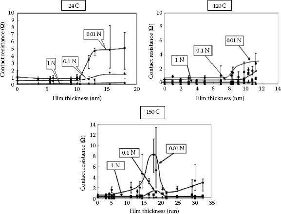
FIGURE 5.16
Relationship between contact resistance and oxide film thickness for tin exposure at 25°C, 120°C, and 150°C.
The subject of corrosion was introduced in Chapters 2, 3, and 4. Corrosion is a chemical or electrochemical reaction between a metallic component and the surrounding environment causing detectable changes that lead to a deterioration of the component material, its properties and function. It begins at an exposed metal surface altering progressively the geometry of the affected component without changing the chemical composition of the material or its microstructure. Degradation initiates with the formation of a corrosion product layer and continues as long as at least one of the reactants is able to spread through the layer and sustain the reaction. The composition and characteristics of the corrosion product layer can have a significant influence on the corrosion rate. Among the many forms of general corrosion that could potentially affect the power equipment metallic components atmospheric, localized, crevice, pitting and galvanic are probably the most common.
5.4.7.1 A tmospheric Corrosion
Atmospheric corrosion is the gradual degradation or alteration of a material by contact with substances such as oxygen, carbon dioxide, water vapor, and sulfur and chloride compounds that are present in the air. Uniform thinning of component material is probably the most common form of general corrosion. Due to the electrolytic nature of corrosion, only a very thin film of water is needed to accelerate degradation. Although the rate of atmospheric corrosion is dependent on the humidity, temperature, and levels of sulfate, chloride, and other atmospheric pollutants, it is usually not constant with time and tends to decrease as the duration of exposure increases.
Localized corrosion is similar to general corrosion except the rate of attack is usually much faster and the size of the affected area is significantly smaller. Damage caused by localized corrosion is often difficult to detect and quantify because visible surface flaws tend to be small and often do not provide a good indication of the extent of damage that has occurred under the surface. Specific forms of localized corrosion include crevice, pitting, and localized biological.
Crevice corrosion is a form of localized attack of a metal surface adjacent to an area that is shielded from full exposure to the environment because of the close proximity between the metal and the surface of another material. Narrow openings or spaces between metal-to-metal or non-metal-to-metal components, cracks, lines, or other surface flaws can serve as sites for corrosion initiation. Humidity and pollution can penetrate into a crevices and cavities inside mechanical and compression connectors not filled with contact lubricant. In the bolted connectors, the bolts made of stainless steel are more prone to crevice corrosion than those of carbon steels, especially in the presence of chlorides. The initiation of crevice corrosion is illustrated schematically in Figure 5.17 [19]. The simplest method for preventing crevice corrosion is reduced crevices in the design of the structure, improving drainage and sealing of edges or keeping crevices as open as possible thus preventing entry of moisture. A protection method called “hot wax dip,” commonly used in the automotive industry, involves the painting of surfaces before assembly. Cathodic protection is also found to be an effective method against crevice corrosion, but anodic protection is often wrong. The use of alloys which are less vulnerable to crevice corrosion is another protection method. Also, addition of inhibiting substances to bulk solution is found to be a very effective protection method. Application of passivating compounds such as chromate and nitrate is another effective and practiced method. Another protective measure is overlaying susceptible areas with an alloy which is more resistant to crevice corrosion. The use welds rather than bolted or riveted joints is also a way of limiting crevice corrosion.
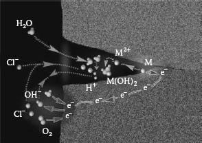
FIGURE 5.17
Schematic of crevice corrosion initiation. (Courtesy of Laboratoire de Physicochimie Industrielle.)
Pitting corrosion is localized degradation of a metal surface confined to a point or small area that takes the form of cavities. The pits are generally irregularly shaped and may or may not get filled with corrosion products. Pitting usually affects metals that are covered with a very thin coating with the pits forming at weak spots in the coating and at sites where the coating is damaged mechanically under conditions where self-repair will not take place. The stainless steels are particularly sensitive to pitting corrosion, but other metals, such as passive iron, chromium, cobalt, aluminum, copper, and their alloys are also prone to this pattern of damage [19]. Typical case of pitting corrosion is shown in Figure 5.18. Pitting corrosion is frequently observed in CO2 and H2S environments. Pits are generally initiated as a result of local breakdown of corrosion product films on the surface and corrosion will continue at an accelerated pace. Pits may become connected as the corrosion damage increases. Corrosion products are dark brown to grayish black and loosely adhering. In H2S systems, the pits are usually shallow round depressions with etched bottoms and sloping sides. Broadly speaking, the pits are not connected, and corrosion products are black and tightly adhering to the metal surface.
Pore corrosion occurs in thin porous plating in the as a result of galvanic cell formed in the presence of a thin water layer containing ionizable gas. The corrosion products are transported from the reactive base or substrate metal though the hole in the plating to the contact surface. This type of corrosion is usually associated with a synergistic effect between chlorides, oxygen and/or sulfates and is evidenced by the appearance of the pores which are defects in a coating which expose the underlying metal, underplate or underplate and substrate (see Chapters 2, 3, 4, and 8).
Creep corrosion can occur when a reactive substrate metal like silver on copper is located next to and in physical contact with a noble metal or a noble alloy inlay of plating. The substrate metal corrosion products creep over the noble metal surface. Creep can also be initiated from the pores in the thin gold plating. This corrosion process is usually associated with copper sulfide and silver sulfide corrosion films. The appearances of pore and creep corrosion are shown in Figure 5.19.
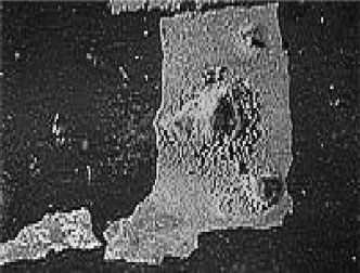
FIGURE 5.18
Example of pitting corrosion in a copper tube. (Courtesy of Laboratoire de Physicochimie Industrielle.)
This type of corrosion occurs owing to presence of water-soluble salts in the dust. Such solutions form electrolyte and causes metal to rust. This problem has been extensively studied in China by Zhang and his associates [20] who have indicated that the relative humidity and in particular the pH factor was one of the most important parameters affecting dust corrosion. It appears the corrosion of dust particle increases almost linearly with relative humidity as seen in Figure 5.20 whereas the typical appearance of corrosion product around the dust particle is indicated in Figure 5.21 (See Chapter 4).
In a bimetallic system, galvanic corrosion is one of the most serious degradation mechanisms (See Chapters 2 and 8). Whenever dissimilar metals are coupled with the presence of solutions containing ionized salts, galvanic corrosion will occur. The driving force behind the flow of electrons is the difference in voltage between the two metals with the direction of flow depending on which metal is more active. The more active (less noble) metal becomes anodic and corrosion occurs while the less active metal becomes cathodic (see Table 2.2). Figure 5.22a shows schematic of galvanic corrosion in aluminum-to-copper joints whereas Figure 5.22b shows an example of typical corrosion damage in aluminum-to-copper compression connector. In the case of aluminum-to-copper connections, aluminum (the anodic component) dissolves and is deposited at the copper cathode in the form of a complex hydrated aluminum oxide, with a simultaneous evolution of hydrogen at the cathode (copper). The process will proceed as long as the electrolyte is present or until all the aluminum has been consumed, even though the build-up of corrosion products may limit the rate of erosion at the surface. The aluminum-to-copper connection is affected by corrosion in two ways: either the contact area is drastically reduced, causing an electrical failure, or the connector is severely corroded, causing a mechanical failure. In most cases, failure is owing to a combination of both effects. The factors that determine the level or severity of galvanic corrosion are numerous and complex but probably the most important is humidity. In order to limit the damaging result of galvanic action in corrosive environments and maintain a low contact resistance, various palliative measures such as plating with a metal of intermediate galvanic potential, contact aid-compounds and transition washers have been used. Corrosion behavior of different material combinations in power connectors and recommended mitigating measures taken to suppress the deleterious effect of corrosion are summarized in Table 5.4.
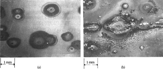
FIGURE 5.19
(a) Pore corrosion and (b) Pore and creep corrosion.
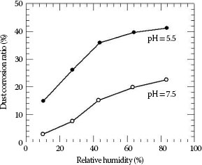
FIGURE 5.20
Corrosion ratios of dust particles with different pH as a function relative humidity.
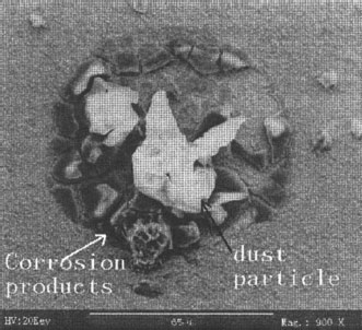
FIGURE 5.21
SEM images of the corrosion product around dust particle.
The difference in the coefficients of thermal expansion of two different contacting metals is another important factor in the degradation mechanisms. For aluminum-to-copper connections, the aluminum expands at a greater rate than copper when exposed to an increase in temperature. As a result, either large lateral movements occur in the contact zone shearing the metal-contact bridges, thus reducing the contact area, or plastic deformation takes place in a region adjacent to the contact interface. This loss increases the contact resistance which, in turn, causes the connection temperature to rise. At higher temperatures, the stresses may be relieved by a recovery in the matrix. On cooling, however, the thermal stresses build up again and further interracial shearing and/or plastic deformation occur since at lower temperatures there will be very little recovery in the matrix and thus little stress reliever. When the process is repeated many times, considerable plastic deformation in the contact zone will occur if the thermal stresses generated are greater than the yield stress of the aluminum. The end result is a cascading effect which accelerates the degradation of the connection until failure. A simple estimate of the magnitude of the maximum elastic stresses generated at the peak temperature in a thermal cycle for aluminum-to-copper connections can be calculated by assuming that the thermal stresses generated in the aluminum are negligible, since the sample is effectively annealed. On cooling, both aluminum and copper will contract by the amount Δ d given by
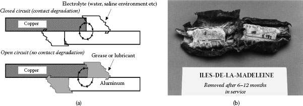
FIGURE 5.22
Schematic of galvanic corrosion in aluminum-to-copper joints (a) and (b) example of corrosion damage in aluminum-to-copper compression connector.
TABLE 5.4
Corrosion Behaviors of Different Contact Materials Combinations and Mitigating Measures Required to Suppress the Effect of Corrosion
Material Combination |
Corrosion Behavior |
Mitigating Measures |
Aluminum/Copper (alloy) |
Severe corrosion of aluminum surfaces in saline environment |
Lubrication and use of Al transition washers |
Aluminum/Tin-plated Copper (alloy) |
Plating thickness < 10 μm severe corrosion |
Lubrication |
Plating thickness > 10 μο no severe corrosion |
Use lubricated Al transition washers. |
|
Aluminum/Silver-Plated Copper (alloy) |
Plating thickness > 5 μm |
Lubrication not required |
No severe corrosion of the contact zone |
Current-carrying contact-pairing should be avoided due to formation of intermetallics. |
|
Tin-Plated Aluminum/Copper (alloy) |
In industrial environment corrosion of tin and its peeling intensifies corrosion of aluminum |
Remove tin and lubricate Use lubricated Al transition washers. |
Tin-Plated Aluminum/Tin-Plated Copper (alloy) |
Plating thickness < 10 μm no severe corrosion of aluminum surface |
Remove tin and lubricate Use lubricated Al transition washers. |
Nickel Plated Aluminum/Copper (alloy) |
If not protected corrosion at nickel-aluminum interface in saline environment can occur |
Lubrication |
Nickel-Plated Aluminum/Nickel-Plated Copper |
If not protected corrosion at nickel-aluminum interface in saline environment can occur |
Lubrication |
(5.12) |
where εt is the coefficient of thermal expansion and ΔT is the temperature change. The differential strain owing to the constraint is then
(5.13) |
Since for aluminum αt = 24.0 × 10⁻⁶ (1/°C) and for copper αt = 17.2 × 10⁻⁶ (1/°C) the corresponding differential strains for aluminum-copper contacts at 100°C, 150°C and 200°C are respectively 6.8, 10.2, and 13.6 × 10⁻⁴ (1/°C). The tensile yield strength of aluminum is 55 MN/m2 and the elastic modulus 70 GN/m2, hence the yield strain is 7.8 × 10⁻⁴ (1/°C). Comparison with the calculated differential strain values above indicates that the aluminum should yield during cooling of the contact.
Another consequence of the greater thermal expansion of aluminum is thermo elastic ratcheting [21]. In a bolted aluminum-to-copper joint where a steel bolt is used, excessive tightening of the bolt can plastically deform the aluminum and copper conductors during the heating cycle which cannot regain their original dimensions during the cooling cycle. Repeated heating and cooling cycles can thus cause loosening of the joint, which in turn will increase the joint temperature and contact resistance. The effect of thermoelastic ratcheting on the mechanical integrity of a bolted joint with different types of mechanical contact devices under current cycling conditions was investigated by Braunovic [21]. It was shown that the detrimental effect of thermoelastic resulting in the form of loosening of joints can be considerably reduced by disc-spring (Belleville) washers in combination with thick flat washers. The least satisfactory performance was observed in joints comprising lock-spring (Grower) and thin flat washers. This effect, illustrated in Figure 5.23, shows a comparison of the loss in contact force during the static relaxation test and the residual contact force remaining in the joint during the cooling periods (OFF) of current cycling.
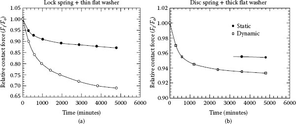
FIGURE 5.23
Effect of thermo-elastic ratcheting on the mechanical integrity of bolted aluminum joints.
The difference between the static and dynamic (current cycling) stress relaxation is considered as a measure of the thermoelastic ratcheting effect. The results, presented as changes in the relative contact force with time, show that the thermoelastic effect is considerably reduced when disc-spring and thick flat washers were used. Joints with lock spring and thin flat washers are strongly affected by the thermoelastic ratcheting as manifested by a substantial loss in the contact load during current cycling and loosening of a joint, which, in turn, increases the contact resistance and temperature possibly to the point of failure. It is important to note that the use of lock-spring and thin flat washers is a common practice in the electrical industry; In view of these results it this practice is not recommended.
Recently Schlegel et al. [6] showed that different ageing mechanisms are responsible for the long-term behavior of bolted joints used in high current systems. One of these mechanisms is the debasement of the joint force depending on temperature and time. If the joint force falls below a critical value, the joint resistance, the thermal dissipation and thereby the temperature of the joint can increase to a critical level. According to IEC 61439-1 the highest accepted temperature of joints is 140°C. The influence of the force reduction to the ageing of joints is tested on current-carrying, bolted Cu-ETP (CW004A) busbar joints using washers and spring washers. The temperatures used were up to 160°C. The joint force and the joint resistance are measured as a function of time. The possible physical mechanisms for the long-term tests and the results of microscopic investigations of the busbar material are discussed. On the basis of this experimental data an extrapolation of the lifetime of such electrical joints is discussed in relation to the practical operating lifetime of more than 50 years.
Fretting (see also Chapters 6 and 7) is a common problem of significant practical importance that can affect a wide range of electrical equipment and can incur costly component replacement and even more expensive equipment downtime. The process is defined as accelerated surface damage occurring at the interface of contacting materials subjected to small oscillatory movements. The required oscillatory movement of the contacting members can be produced by mechanical vibrations, differential thermal expansion of contacting metals, load relaxation, and by junction heating as the power is turned on and off. It is generally accepted that fretting is concerned with slip amplitudes not greater than 125 μm. The sequence of events leading to the development of the fretting damage at the contact interface is described in Figure 5.24. Although the adverse effects of fretting were observed as early as 1911 [22] at the contact surfaces of closely fitting machine elements subjected to vibration and correctly diagnosed as mechanical in origin. The phenomenon was given little attention until 1927 when Tomlison [23] coined the term “fretting corrosion” to handle this kind of surface damage. This definition includes fretting wear, fretting fatigue, and fretting corrosion. The evolution of fretting damage at the contact interface of different contact materials is illustrated in Figure 5.25 As it can be understood irrespective of the contact metals used, the occurrence of fretting damage is quite obvious. Systematic studies of electronic connectors having tin- and solder-plated contacts and numerous reports of failures in service indicate that fretting is one of the prime failure mechanisms. In the event of power electric connections, however, very little published information or reports of failure owing to fretting are available, for two main reasons. First, there is a general lack of awareness of the problem, since fretting is a time-related processes. Second, the effects of fretting are not readily recognizable, since the failure of a power connection is commonly associated with the destruction of the contact zone by arcing, thus making identification of the fretting products rather difficult.
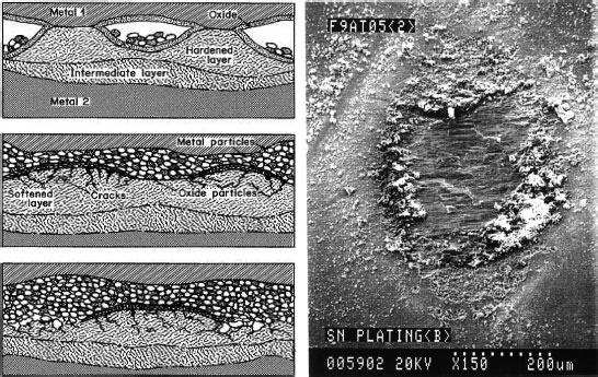
FIGURE 5.24
Schematic of evolution of fretting damage in electrical contacts and a SEM image of a typical fretting wear damage of the contact zone.
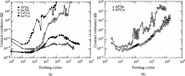
FIGURE 5.25
Evolution of the fretting damage at the contact interface of different contact materials.
5.4.11.1 Factors Affecting Fretting
The nature of fretting depends on a multitude of variables. Many hypotheses have been proposed to account for the effects observed but no unified model for the process has yet emerged and no single theory has yet been established as correct to the exclusion of any other. Detailed explanations of the present state of the art have been given by Campbell [24], Waterhouse [25], Golego [26], and Hurries [27].
Factors known to affect fretting may be divided into three broad categories, namely:
• Contact conditions,
• Environmental conditions
• Material properties and behavior.
Factors affecting fretting are schematically illustrated in Figure 5.26. As shown, these ingredients may interact with one another and influence both the nature and the extent of fretting damage. Under certain conditions, the effects of environment may be excluded from the contact area and, therefore, will have no strong influence on fretting. But then, under different contact conditions the same environment may have ready access to the contact zone and have a strong influence. It is clear that adequate simulation of any practical fretting wear problem, contact conditions, fretting load levels and amplitudes, materials, and environmental conditions must be studied. The fretting process is too complex to enable extrapolation with confidence from one set of conditions to another very different set of conditions. Two basic conditions for fretting to occur are relative movement or slip and amplitude of motion sufficient to cause the damage. Experimental evidence shows that amplitudes of the order of 10−8 cm (<100 nm) are sufficient to produce fretting [25]. Thus, from a pragmatic standpoint, there seems to be no minimum surface slip amplitude below which fretting will not occur. Although there may be a debate as to the upper limit which may still modify the process as fretting, there is no doubt that in situations where microslip prevails, that is, where slip occurs over only part of the contacting surface, the cause is only characteristic of fretting. Mindlin [28] has demonstrated that the minimum slip amplitude for fretting to occur is given by
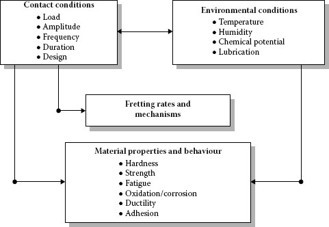
FIGURE 5.26
Schematic representations of the factors affecting fretting.
(5.14) |
where a is the diameter of the contact outer radius, E is the Young modulus, ν is Poisson’s ratio, P is the normal force, μ is the static coefficient of friction between the contact surfaces and T is the tangential force (T < μP). Figure 5.27 illustrates a classic example of microslip occurring between a steel ball and flat, where the ball has an oscillating tangential force. It is generally agreed that fretting damage increases with increasing amplitude and that the mechanical properties of the contacting materials significantly affect the threshold value for fretting to occur [28].
5.4.11.2 Mechanisms of Fretting
One of the first theories for fretting corrosion was advanced by Tomlison [23] who suggested that fretting corrosion is caused by molecular attrition. The cohesion between atoms and molecules which arises as they approach causes them to detach from the surfaces and subsequently become oxidized. Tomlinson argued that fretting corrosion is not influenced by the normal load because, according to him, molecular attrition is independent of external forces. Godfrey [29] proposed that fretting damage occurs as a result of adhesion between the surfaces. The wear debris is extruded from the contact area and reacts with the environment. Nonetheless, good adhesion between two oxide-covered surfaces is questionable. Feng and Rightmire [30] stated that fretting begins with adhesive wear followed by a transition period in which accumulation of the trapped wear particles gradually contributes to abrasive action. Eventually the damage is solely caused by abrasion. The occurrence of loose wear particles is attributed to plastic deformation at the contacting high spots. Uhlig [31] proposed that chemical and mechanical factors are responsible for fretting corrosion. An asperity rubbing on a metal surface produces a track of clean metal, which immediately oxidizes or upon which gas molecules rapidly adsorb. The following asperity wipes off the oxide or initiates the reaction of metal with adsorbed gas to form oxides. This is the chemical factor of fretting. In addition, asperities penetrate below the surface to cause wear by a welding or shearing action by which metal particles are dislodged. This is the mechanical factor of fretting. Stowers et al. [32] identified two different regimes of fretting as a function of amplitude. In the low-amplitude regime, the volumetric wear per cycle is a function of the amplitude squared, whereas in the high-amplitude regime it is directly proportional to the amplitude. They suggested that material loss resembles that produced by unidirectional adhesive wear much more closely than that produced by other modes of wear. Consequently, the amount of wear can be computed using Archard’s adhesion model for wear [33] which requires that when asperities come into contact and adhere strongly to each other, the subsequent separation occurs in the bulk of the weaker asperity in a single action. This procedure is assumed to produce an atom from the softer surface which adheres to the harder surface. When these transferred particles become free, loose wear particles are formed and wear, observed as weight loss, is assumed to occur. Oding and Ivanova [34] stated that fretting is associated with a thermoelectric effect that causes electro-erosive action at the contacting surfaces. Material from one surface, anodic with respect to the other, is being removed from atoms torn from the surface by the direction of the electric field. Atoms moving in to fill the vacant sites at the surface resulting in vacancy diffusion in the region below the surface. The concentration of vacancy increases until a critical concentration is achieved when they coalesce as micropores and microcracks. This means that only one of the surfaces undergoes damage. By passing the countercurrent or by choosing suitable pairs of metals for the contact, this could be reversed. Although attractive, this theory cannot explain why surface damage arises between two similar metals, unless the thermoelectric effect of an oxide film is invoked. Suh [35] proposed a delamination mechanism of wear which involves the initiation of subsurface cracks which propagate parallel to the surface and lead to detachment of flakes 0.1–20 μm thick. These fractures are thought to initiate at voids and vacancies developing from dislocation pileups below the surface layer, and at a critical length, the cracks shear to the surface. It should be emphasized that the delamination theory of wear as it stands is applicable only for the case of low-speed sliding, where the temperature rise at the contacting surface is so low that diffusion and phase transformation are not involved in the wear process.
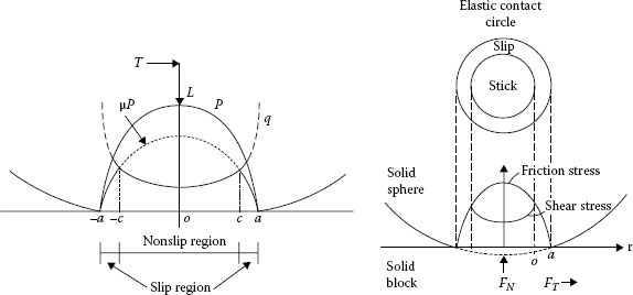
FIGURE 5.27
Microslip occurring between a flat and steel ball under oscillating tangential force.
The delamination mechanism of wear was used by Waterhouse and Taylor [36] to explain the formation of loose wear particles and the propagation of subsurface cracks in the fretting surfaces. The end result of this process is the detachment of oxide-coated plates of metal about 1.3–3.5 μm thick. The continuing fretting action grinds the initial wear particles down to particles of smaller size with higher oxide content. They also divided the fretting corrosion process into two stages. Adhesion occurs in the early stage of fretting and it is more significant with noble metals or in an inert environment. When this stage is passed, the surfaces become smooth and removal of material from the surfaces occurs by delamination. The transition from adhesion to delamination is a function of the material and the nature of the surroundings. Sproles et al. [37] concluded from the observed mode of metallic material removal that fretting wear by a delamination mechanism is predominant, rather than an abrasive wear mechanism or a welding and material transfer mechanism. Oxide debris is formed by the oxidation of metallic debris or by the constitution and subsequent scraping away of a thin oxide film from the metal surfaces. Godet [38] proposed a third-body concept and a velocity accommodation mechanism. The debris formed in the contact remains in the interface for several cycles, and fretting has to be viewed as a three-body contact. This approach focuses on the role of the third-body material which separates the two first bodies rubbing through its load-bearing capability. Directly transposed from the lubrication theory, this concept emphasizes notions of third-body flow and velocity accommodation. Noël et al. [39] examined the fretting behavior of nickel coatings with two types of deposits for electrical contact applications Sulfate nickel layers are electrodeposited in different conditions and show very different behaviors during fretting tests. The characteristics of the layers are analyzed and show different compositions and microstructures. The compositions are measured by X-Ray Photoelectron Spectroscopy (XPS) which allows determining the chemical nature of the compounds formed during exposure to air. Topography is measured by AFM and the roughness and grain characteristics are measured. Electrical properties at the micro/nanoscale are measured with the CP-AFM technique. Various loads are applied to the cantilever beam; the electrical characterization is performed versus the load.
The results of fretting experiments are analyzed in terms of fretting regimes. The fretting regimes occurring during the test of nickel layers involve partial slip which delays the occurrence of contact resistance (Rc) increase (Figure 5.28). Gross slip in the interface is shown to create very poorly conducting wear debris leading to drastic increase of Rc. Bright nickel is compared to matte nickel in a fretting test simulating the micro-displacements caused by vibrations. A drastic increase of the resistance is observed with bright nickel while with matte nickel a partial slip regime sets up which postpones the failure of the contact. This behavior is related to the microstructure of the coating which depends on the mechanisms of evolution of texture in nickel electro-deposits. Bouzera et al. [40] determined the minimum fretting amplitude in medium force for connector coated material and pure metals. For automotive applications, the mechanical behavior of the contact area under vibrations is one of the key components for connector reliability. Such vibrations are typically in the range of 10–2000 Hz and result in displacements of only a few microns, at the contact interface. In the present study, a bench test has been developed to control more representative motions down to 1 μm. The objective is to determine the minimum amplitude for fretting-corrosion degradation on the basis of the evolution of contact resistance and to study the effects of the material, the contact force, the coating for these low displacement amplitudes.
To obtain the limit of the appearance of fretting, a sub-micrometer incrementing displacement amplitude methodology was used on high stiffness bench test including a double PZT actuator. It was found that the fretting degradation starts to occur from 2 to 6 μm when the contact force is from 0.5 to 2.5 N with a tin coated terminal (Figure 5.29). Moreover pure copper, tin, and nickel have similar amplitudes fretting limits while noble metals confirm the absence of fretting up to 10 μm amplitude and for a large number of operations (106 cycles). Best fitting of the obtained minimum fretting amplitude data to Mindlin equation is discussed and amended by correcting factor. It was found that hard materials like Ni need higher amplitude than softer material like Sn to enable fretting whereas coating material in connector needs higher amplitude than pure metal of coating For non-noble materials as (Cu, Sn, Ni), the lifetime of the electrical contact is limited, the electrical contact resistance is sharply increased at amplitude as low as few μm, and its lifetime is dependent on the kinetics of forming an insulating layer of oxidized debris. However a noble metal as (Ag), their lifetime of the electrical contact is unlimited and no minimum fretting amplitude up to 12 μm is observed, its electrical contact resistance is stable and low because its debris does not oxidize. The theoretical data of minimum amplitude calculated from Mindlin model seems to be different with experimental data for the used materials. Since the experimental procedure used does not completely respect the Mindlin assumptions of the theoretical model, a correcting factor C is then introduced into the Mindlin equation to improve the convergence. Future work could discuss and determines the way this discrepancy depends on other contact materials and the test conditions. It is necessary to quantify the amplitude of transition at which fretting starts when an electrical contact is subjected to micro-displacement tests. A method of incrementing amplitude has been applied to different types of materials. This technique easily allows the detection of the transition between P.S. regime and G.S. regime for each material that corresponds to fretting appearance.
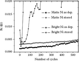
FIGURE 5.28
Contact resistance Rc during the first cycles of fretting experiments performed on matte and bright coatings as received and after storage.
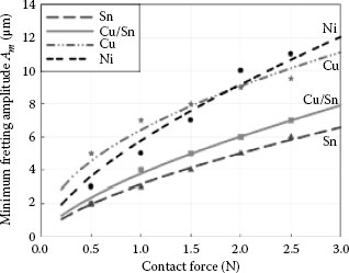
FIGURE 5.29
Minimum fretting amplitude Am versus normal force for copper tin-coated and pure metals Sn, Ni, and Cu-(symbol) experimental data and (line) theoretical data.
Although there is still no perfect unanimity on the mechanisms of fretting, particularly with respect to the relative importance of the processes involved, it can be safely assumed that the following processes are present:
1. Disruption of oxide film on the surface by the mechanical action exposes clean and strained metal which will react with the environment and rapidly oxidize.
2. The removals of material from the surfaces by adhesion wear delamination or by shearing the microwelds formed between the asperities of the contacting surfaces when the contact was made.
3. Oxidation of the wear debris and formation of hard abrasive particles that will continue to damage the surfaces by plowing.
4. Formation of a thick insulating oxide layers and wear debris (a third body) between the contacting surfaces.
5.4.11.3 Examples of Fretting Damage in Power Connections
Aluminum, copper, and plating materials such as tin, nickel, and silver are the most common contact materials. One of the major problems associated with the use of these materials in electrical applications is the occurrence of fretting. Fretting may not contribute directly to the failure of a connection, but it is definitely one of the prime factors causing electrical instability and subsequent joint failure. Although contact resistance was used to monitor the development of fretting damage in steel specimens as long ago as 1956 [41], it was only eight years later that Fairweather et al. [42] revealed how fretting can cause considerable instability and serious degradation of telephone relays and switches. The deleterious effect of fretting, however, was not widely recognized as a serious factor in the degradation of electrical connections until 1974 when Bock and Whitley [43] clearly showed its importance. Since then, systematic studies of electronic [44,45,46,47,48,49,50] and automotive [51] connector systems and reports on in-service [52,53] failures have established that fretting is one of the major contact deterioration mechanisms in dry connections. The phenomenon appears to be inherent in all contact and conductor materials such as gold, palladium, tin, nickel, silver, copper, and aluminum [47,48,49,50,51,52,53,54,55,56,57,58,59,60,61]. A comprehensive review of fretting in electrical connections has been given by Antler [62,63], while Mallucci [64] and Bryant [65] provided comprehensive models to predict the contact resistance behavior under fretting conditions. The result of fretting is of considerable importance to power connections involving aluminum. This is because dry aluminum contacts are most susceptible to fretting damage since hard aluminum-oxide particles easily abrade the contacting metals. This, in turn, will initiate the oxidation of exposed materials and accumulation of highly insulating fretting debris at the contact interface. As a result, the contact resistance will increase at a very high rate thus raising the joint temperature which, in turn, will accelerate the deterioration of the contact members.
5.4.11.4 Compression Connectors
In the case of compression connectors, such as shown in Figure 5.30, when two dissimilar metals are pressed against each other, surface asperities will penetrate the natural oxide films providing a good metallic contact. Also, because of the highly localized contact stresses, the asperities will be severely deformed and there will be the mechanical seizure of the contacting metallic surfaces. In the case of unprotected (non lubricated) aluminum over unprotected copper (Figure 5.30a), an increase in temperature causes the outer aluminum portion of the connection to expand at a rate greater than that of the copper thus generate fretting motion at the contact interface and shear the metallic bridges. This, in turn, will cause a loss of contact surface area. Exposed to the atmosphere, aluminum oxidizes resulting in further reduction of the contact area when the connection returns to the initial temperature.
With unprotected copper over unprotected aluminum (Figure 5.30b), the latter expands in the axial direction since the residual stress in the copper and its lower rate of thermal expansion restrict the wire to expand circumferentially. If the axial stress exceeds the elastic limit of aluminum, a permanent deformation result, and the wire will not revert to its original compressed position contact. Dang and Braunovic [66] used wire-to-sleeve resistance mapping together with SEM (Scanning Electron Microscopy) and X-Ray Analysis (EDX) techniques to study the contact resistance and metallurgical changes of compression sleeve connectors in aluminum cable splices following accelerated aging tests. It was shown that fretting and thermomechanical movements resulting from current cycling are the most probable cause for the degradation and overheating of these connectors. Another example of the effect of fretting is shown in Figure 5.31. It depicts the fretting damage originated at the copper windings that resulted in the loss of insulation and accumulation of the copper debris between the transformer windings [67].
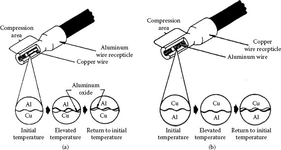
FIGURE 5.30
Compression connection between (a) aluminum terminal and copper conductor; (b) copper terminal and aluminum conductor.
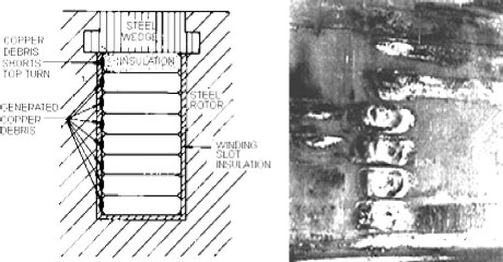
FIGURE 5.11
Fretting damage in power generators.
Field experience with separable power contacts involving aluminum busbars has indicated failures in certain industrial locations. These were evidenced by mechanical erosion and electrical burning of metal at the contact areas resulting ultimately in open-circuit condition. Johnson and Moberly [68] have investigated the effect of fretting on the performance of bus-stab contacts with tin- and silver-plated aluminum busbars under normal operating conditions. It is now recognized that bus-stab contacts are subjected to three modes of mechanical motions, illustrated in Figure 5.32. The first mode occurs when the busbars are subjected to variations in electrical load, changing their length owing to thermal expansion. This results in slow slide motions with respect to the stab contact (direction A-A, Figure 5.32a) which, in turn, causes elongation of the stab contact area along the busbar. This was confirmed by the burnished track on an actual aluminum bar. These relatively slow induced motions are a function of bus-run length and temperature changes and, consequently, will be relatively short in many applications. The second mode of motion (direction B-B, Figure 5.32a) is attributed to electromagnetically induced vibrations. The driving force for these motions is created by currents flowing in adjacent bus members. In common busway configurations, the forces between busbars can be as large as 100 N/m of busbar length under rated current conditions. Such forces can cause busbars displacement of the order 20 μm perpendicular to those induced by thermal expansion. The third way of bus-stab contact motion is transverse displacement perpendicular to both thermal and electromagnetically induced motions (direction C–C, Figure 5.32a and b). It is owing to rigid stab mounting and the vibratory motions discussed above. An illustration of how such “transverse” motions are generated is shown in Figure 5.32b. As the busbar vibrates to the right of its resting or neutral position, owing to the motion shown as B-B in Figure 5.32a, the stab’s two contacts are constrained to move in a transverse direction. One contact moves upward and the other downward along the bar, as they follow their respective arc lines. Busbar vibration to the left results in reverse transverse motion of the stab contacts. The frequency of these rubbing transverse movements is identical to that of the electromagnetically induced vibratory motions, 120 Hz, from which they are generated. On the basis of the physical dimensions of a typical 400 A stab, and under normal electrical load conditions, the relative displacement of bus-stab contacts owing to transverse motions is required to be less than 25 μm. Although such motion displacements are small, significant fretting wear of the bus or the plating may occur because of the increasing number of slides. The resulting degradation of protective platings would lead to the establishment of high-resistant films, surface damage and arcing, which, in turn, favors more chemical attack, burning and failure of the contact metals.
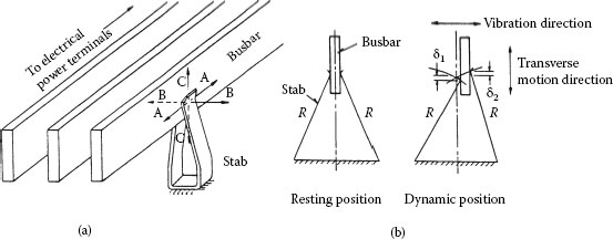
FIGURE 5.32
(a) Direction of mechanical motion acting on bus-stab: (b) Transverse motion of slab contact along busbar width contacts.
Contact area distress of 95% and 15% was observed following tests of tin-plated and silver-plated stabs, respectively. Distress percentages were assigned by the authors and they represent judgments on the basis of the preliminary contact failures being 100%. An indication of contact distress related to the bus-stab interface contact materials may be obtained from the micrographs in Figure 5.33. Contact distress becomes very small when transverse sliding motions of the stab are reduced to 5 μm. It is most likely that, at this level of motion, inherent resiliency of the stab actually prevents relative slide thus reducing abrasive rolling or rocking motion. Direct correlation with the above observations of distress is found in the contact voltage and bulk temperature values shown in Table 5.5. When a tin-plated stab was combined with the silver-plated aluminum bar, contact voltages greater than 270 mV were measured. However, in the case of silver-plated bus-stab contacts subjected to pulsed and steady electrical loads of 1,000 and 400 A, relatively low values of contact voltage of 31 and 12 mV respectively were measured. The best performance is obtained when the contact members are plated with silver, rather than tin, and mechanically held together with forces of at least 70 N. Nevertheless, when the contact members are subjected to 120 Hz, relative slide motions with amplitudes greater than 5 μm the time to failure is greatly shortened. Hence, unless transverse motions can be minimized below the critical amplitude level, bus-stab protective metal platings will wear at appreciable rates and eventually be worn out, resulting in higher contact resistance and temperature and final “burn” failure.
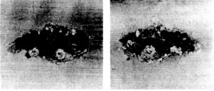
FIGURE 5.33
Contact zone after distress caused by transverse sliding motion of bus-stab interface.
TABLE 5.5
Bus -Staba Electrical Contact Performance Characteristics
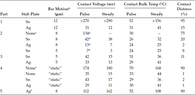
a. BusBar: Ag plated Al: Electrical load 1,000 A(rms)–46 hr., 100 A(rms)–4 hr. Stab: Cu-Cd alloy: Contact load 70 N
b. 120 Hz double motion frequency
c. 3 hour run
d. Electrical load 250 A(rms)–46 hr., 100 A (rms)–4 hr.
e. Unplated Al busbar
f. Sn plated Al busbar