
I wish I did not have to write the instruction manual on the uses of a new metal.
The Instruction Manual, John Ashbery
CONTENTS
17.1.1 Arc-Induced Contact Stresses and Interface Bond Quality
17.2 Staked Contact Assembly Designs
17.2.1.2 Machine-Made Composite Rivets
17.2.1.3 Brazed Composite Rivets
17.3 Welded Contact Assembly Designs
17.3.2 Special Welding Methods
17.3.2.2 Ultrasonic Welding of Contacts
17.3.2.3 Friction Welding of Contacts
17.4 Brazed Contact Assembly Designs
17.4.1 Methods for Brazing Individual Parts
17.4.1.3 Direct and Indirect Resistance Brazing
17.4.1.5 Continuous Laminated Strip Brazing, “Toplay”
17.4.1.6 Brazed Assembly Quality Control Methods
17.5 Clad Metals, Inlay, and Edge Lay
17.6 Contact Alloys for Non-Arcing Separable Contacts
17.6.2 Manufacturing Technology
17.6.3 Physical and Chemical Properties
17.6.4 Metallurgical Properties
17.6.5 Contact Applications and Performance
This chapter provides information for arcing contact design and information on methods used for attachment of contacts. It is the intent of this chapter to provide technical information useful for the contact user and not to discuss detailed methods used by various companies to make these contact designs. The chapter also contains a section on materials and contact designs used for non-arcing separable, dry circuit, and contact applications.
17.1.1 Arc-Induced Contact Stresses and Interface Bond Quality
In the following sections of this chapter, several different contact design options are discussed. Today most contact designs are composite metal structures having precious metal faces attached to a copper type base as opposed to a monolithic structure of precious metal since the cost of precious metals is very expensive. All discrete contacts have an interface between the contact and the device carrier blade or terminal. All composite contact structures have an additional interface between the precious metal contact face and the base metal part of the contact. Understanding the importance of the contact interface bond quality is a property that is sometimes ignored even though in some cases it can have a major effect on the endurance life of a switching device.
Compared to the number of publications made on contact materials very little has been written on contact interface bond quality. Spaeth et al. [1] and Janitzki et al. [2] have written similar papers showing that for high power devices with brazed contacts, the erosion rate of the contacts increases as the void level in the interface increases, especially when the void area exceeds 50% of the joint interface. They also show that voids near the edge of the contacts are more detrimental than voids in the middle of the interface. Shen et al. [3] did a similar study on high current devices and describes contact bond failure in terms of interface peeling from compressive stresses created as the contacts cool after surface melting from the switching arc.
Chen and Witter [4,5] have performed a study on the effect of bond quality for medium current DC devices using bimetal rivet contacts. They show a very large difference in contact switching endurance life, greater than 5/1, between contacts with good interface bonding, (i.e., +90%), versus contacts with poor interface bonds (i.e., 40%). They also state that the level of stress created from surface melting and re-solidification between the surface of a contact and an under layer is related to the temperature of the under-layer at the time the arc melted surface re-solidifies. This can be related as follows:
(17.1) |
Where K is a factor that is dependent on geometry, extent of melting, and other things, L is the linear coefficient of expansion of silver and (ΔT) the temperature difference between the underlayer and the surface at the time of solidification. This stress causes the rivet head of a monolithic structure to curl as shown in Figure 17.1 during endurance switching. It also causes contacts with poor interface bond strength to delaminate and fail from base metal being exposed to the contact face. This type of curling can occur for all silver alloys subjected to arcing [6].
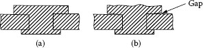
FIGURE 17.1
Typical distortion of rivet head after electrical testing: (a) before testing and (b) after endurance testing.
The stresses created in a contact from electrical endurance testing are more complex than just the stress described from the melting and re-solidification of the surface and include other stresses, such as thermal shock from rapid heating from the arc, annealing of sub-layers of material, and mechanical stresses and fatigue from the pounding of the contacts together. Regardless of the contact silver alloy or the specific discrete contact design some degree of curling is normally present from the melting and solidification cycling from endurance testing and this will vary with contact electrical load level. As the arc energy increases as a function of contact current or arcing time, the surface melting will become more severe and the curling effect will increase. Keeping these factors in mind will help in understanding the advantages and disadvantages of the various contact designs. For example by designing a slight radius for the surface of the contacts, you will not only initially bring the arcing spot and heat dissipation area closer to the center of the contact but also provide some delay in the curling effect reaching the edges of the contact.
17.2 Staked Contact Assembly Designs
Rivets are still one the most popular forms of contact construction for small contacts 2–10 mm in diameter. Figure 17.2 shows typical designs of contact rivets. Rivet constructions can be categorized in several different ways: (1) monolithic versus composite metal construction, (2) bimetal versus trimetal composites, and (3) machine made composites and (4) brazed composites. The bimetal construction uses the precious metal for the contact face and base metal, mainly copper, as the rest of the construction. The trimetal rivets have a precious metal end of the rivet shank plus the precious metal face. The composite constructions for rivets can be made using special heading machines or by forming the separate components and brazing the different materials together which results in significant labor and cost. The process that will be used for an application should be on the basis of both the quality of the contact required and the economics for manufacturing. To make any type of solid or machine made composite, the contact material must be headable, that is, able to be plastically deformed without cracking. Materials that are not headable such as refractory metals, refractory composite materials, many silver graphite compositions and more brittle materials are normally made into rivets by brazing the materials to copper based alloys [7].
This is the simplest rivet design, since no bonding is required for the rivet fabrication. Material deformation without cracking is the only concern. If all contact rivets were made of very low cost materials this design would be used in all cases where the material has sufficient ductility for heading. The main criterion to be concerned with for the design of solid rivets is the ratio of the head diameter to the shank diameter: this ratio depends on the choice of material. In general a ratio of 2/1 is good for many materials. A pure material like fine silver which has a low work-hardening rate can be made using higher ratios. Composite materials, such as some newer silver metal oxides with over 10% by weight metal oxide content, may be better suited for a lower ratio like 1.6/1.

FIGURE 17.2
Different contact rivet designs.
From an economical standpoint it is tempting to design the shank diameter of a rivet to be as small as possible for staking a rivet into backing material. From a technical standpoint, this may or may not be wise, depending on the load and life a rivet will see in service. When a rivet is staked onto a backing or carrier, the most important contact area between the carrier and the rivet is the interface between the cylindrical shank circumference of the rivet and the inside diameter of the hole used for the rivet staking. Figure 17.1 shows an illustration of the typical distortion that takes place on a rivet head after the contact has been subjected to low-current switching duty of about 10 A for several thousand operations. Section 17.1.1 above describes the mechanism creating this curling phenomenon. It can be seen that because of this curling the bottom side of the rivet head and carrier interface contributes little or no heat conduction from the contact. It should be kept in mind that the main heat and current conduction path from the rivet to the carrier is through the interface between the rivet shank OD and the rivet hole ID. The use of a larger shank diameter, even though not economical, can minimize curling and can also provide more interface bond area for conducting heat away from the contact.
17.2.1.2 Machine-Made Composite Rivets
The most popular type of rivet used today is the headed bimetal composite. The heading process for making the rivet not only forms the wires into a rivet shape but also bonds the contact material to copper or in some cases a copper alloy. Many different machines and processes for making these rivets have been developed over the years, some involving different types of electrical welding and others using cold bonding and forming. For example, ordinary resistance welding should not be used for direct bonding silver metal oxide materials to copper since oxide slags generated during the welding prevent good attachment. For this reason, silver metal oxide composite rivets are normally made by cold bonding and forming.
The ability to bond copper and other alloys in intimate contact by solid-state cold deformation is well known [8,9]. The cold bonding process for the attachment of a silver metal oxide to copper to form a contact rivet involves bonding mechanisms comparable to the better-known process of roll cladding. The cold bonding process consists of taking two cylinders, one cut from a copper wire and the other from a silver metal oxide wire, putting two of the flat faces of each metal cylinder in contact with each other and co-expanding each cylinder at the interface to create a bond. As the interface expands you have simultaneous plastic flow of the metals and fracturing of any surface films that may exist on the two components. The intimate metal to metal contact that takes place as a result of this co-expansion forms a bond between the two metals. The bonding process begins in the middle of the rivet and expands out to the circumference as the co-expansion progresses. Even for rivets with good quality interface bonds there is always a small amount of void area near the circumference. The process should also involve some post-forming heat treatment to remove stresses while at the same time producing some solid-state diffusion which further improves the bond quality.
The main concern for the contact user should be the quality of the bond that is created and not the exact process or machine that was used to make this bond. As a result of rivet geometry, it is difficult to measure the strength of this bond. Sometimes the rivet head is thick enough to perform shear testing but small variations in shear interface location cause very large errors in shear results. Many rivets, however, have an alloy layer that is too thin even to allow shearing and also work done by several researchers in an ASTM committee on contacts have found too much spread in shear strength results to be considered as a good test [10]. Two important quality factors for bonds are bond ductility and bond area. Brittle bonds result in the same kind of defect as voids in the bond interface since the bond interface separates under low stress. To evaluate bonds a simple test has been developed, called the squeeze test. An illustration of this squeeze test is shown in Figure 17.3a. In this case, the rivet head is compressed in a direction that is perpendicular to a void that exists in the copper precious metal interface bond. The head of the rivet is compressed from both sides of the diameter down to for example 50% of the original head diameter. Since there is no published standard for this ratio, it is somewhat arbitrary. The 50% ratio has been found by Witter [11] to be more effective than lesser compression for identification of voids and weak bonds in composite rivets. If the compression direction is as shown in this example the void will result in the rivet interface opening up in the rivet head area containing the void. For testing rivets unfortunately you do not know beforehand where a void will exist so you must squeeze test several rivets, (perhaps 5 to 10 from a batch) to insure you compress a void in a direction that will show a separation if significant voids do exist.
In Figure 17.3b, an illustration is shown that provide you a guide for the squeeze test results for different bond interface distributions. Good bonds, >85%, as depicted in (a) of Figure 17.3b will show little or no separation as compared to bonds of 70% or less. The bond level that is acceptable will depend on the application and an agreement between the vendor and the customer. With regard to the life to be expected with composite rivets that have good, >85%, bonds or poor bonds, ~40%, Chen and Witter [4,5] show a large difference in endurance life, see Figure 17.4. At 60 ampere load the good bond composite is comparable to a solid, monolithic, rivet for endurance life. The poor bond composite has less than 20% of the endurance life and fails by the silver metal oxide layer delaminating and falling off. Another test they have conducted for poor interface bonds shows thinner silver tin oxide layers last significantly longer before delamination than thicker silver layers. This unexpected result is supported by Equation 17.1 since the thinner layer would have a bond interface closer to the contact surface and have less of a ΔT difference in temperature. From a process control view point it is difficult to hold intermediate bond quality, therefore bonds of 70% or less would be considered marginal.
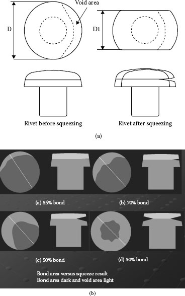
FIGURE 17.3
(a) Typical squeeze test for a composite rivet with weak bond and (b) Different bond distributions with squeeze shape for compression perpendicular to line in bond distribution.
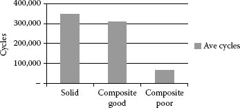
FIGURE 17.4
A comparison of endurance switching life for a solid rivet, good bond bimetal rivet, and a poor bond bimetal rivet.
Other methods also exist for evaluation of bonds including metallographic examination and ultrasonic testing. Cross sectioning of the bond may not give complete information on the bond quality since the cross section represents only one line across the head diameter and it is possible for the bond interface to be very weak and still look good under the microscope. A better method is to squeeze or deform the rivet head to a small extent before making the cross section so that a weak bond will separate. Ultrasonic methods are expensive for checking small parts and also cannot distinguish between weak and strong bonds in intimate contact. Later in this chapter they will be shown to be very effective in evaluating brazed bonds.
Besides the cold bonding and resistance brazing discussed above, special welding processes exist that use an arc for fusing silver alloy materials and copper backings together. This type of welding can be used for attachment of composite materials like silver tin oxide to copper that normal resistance welding cannot accomplish.
17.2.1.3 Brazed Composite Rivets
Before the late 1960s and the development of machines for making composite contact rivets, almost all composite rivets were made by brazing. The brazing process for making composite rivets is much more expensive than the process for making machine composites since three components must be manufactured and then assembled together. The first step in the process consists of making a base metal rivet, contact material disk, and brazing alloy wafer. The components are then assembled together in a brazing fixture which is put through a furnace under a protective atmosphere to fuse the contact material disk to the base metal rivet. Beside cost, brazed composites have other disadvantages compared to machine composites. Firstly, the tolerances of the head diameter and thickness are wider since these dimensions are the product of two components and also the clearance in the brazing fixture must be taken into account. Another problem is the potential for getting brazing alloy running up the sides of the rivet head onto the contact face if the furnace temperature varies. Bond quality also varies with furnace conditions and cleanliness of the components.
The brazing process has the major advantage that brittle materials can be bonded by this method since no deformation is required for making the bond. Therefore, this process is used for making bimetal rivets of tungsten, silver-tungsten, silver-tungsten carbide, silver–graphite and brittle high oxide content silver oxide materials.
Another area where brazed composite rivet designs are used is for contact alloys that work harden rapidly on deformation. For example, silver copper alloys with 10% or more copper are more difficult to join by cold bonding, since co-expansion is difficult to achieve as a result of the large difference in work hardening rate between these alloys and copper. As a result of this, a brazed design may be selected over a machine composite design to obtain better bond quality, especially if the ratio of the head to shank diameter is large.
The bond area of a brazed rivet can be measured easily by cross sectioning the rivet and metallographic examination. The interface is normally 0.02 mm or more in thickness and therefore the voids are visible at low magnification. Since cross sectioning will show only one line through the diameter of a rivet head it is important however to section multiple samples of a given lot to get a representative result for bond quality. Ultrasonic testing and shearing are also effective for evaluating this type of bond.
A common method of rivet attachment is by a straight impact pressing action. The head of the rivet is placed in a die cavity which is shaped to conform to the head dimension and configuration. With the shank of the rivet sticking through a hole in the backing material to which it is being attached a punch presses on the end of the rivet shank to expand the rivet shank diameter to fill the rivet hole. The important factor to be considered for judging the quality of the rivet staking is the amount of contact there is between the outside diameter of the rivet shank and the inside diameter of the hole after staking. The contact area between the underside of the rivet head and the backing material is of little value since, as mentioned earlier, the head of the rivet will tend to curl upward as a result of switching cycling and produce a void in that area.
Orbital riveting is another popular method used for staking rivets. For orbital staking the punch that is supplying the staking force is not parallel to the end of the rivet shank but at a slight angle and rotating. This produces a swaging action that exerts both a radial and downward force on the rivet shank. By use of the orbital process the shank is expanded gradually and a high degree of contact can be obtained between the rivet shank and hole. The orbital process is also used for staking contacts with more brittle contact alloys.
Because staking of rivets is a simpler manufacturing process than welding, it is preferred by many manufacturers of relays and switches. Once the proper tooling and method of staking are developed the process runs very consistently, because there is little wear and the process parameters are easily controlled.
The bond quality from staking varies greatly depending on the tooling and technique utilized. Rivet to backing bonds of 10%–30% are common. Care must be taken, however, even though the rivet shank may appear by visual examination to be bonded well to the backing. Metallographic examination at higher power or mechanical twist tests are recommended to insure a good joint.
17.3 Welded Contact Assembly Designs
For the purpose of this chapter, welding will refer to processes where a contact is fused to a backing material by application of current through the contact and backing which either melts by resistance heating a portion of the contact and backing interface surface or, by some special processes described later in this section, forms an arc that melts the interface surfaces [12]. Figure 17.5 shows the basic components of a simple resistance welder. The current is applied to the contacts by use of two welding electrodes, one applied to the contact, the other to the base metal backing. An electronic weld control unit regulates the amplitude and duration of the current, the timing of the current, and the timing of the electrode force applied to the contacts. The devices for producing the force pushing the contact and backing together vary with different welding equipment but pneumatic air cylinders are widely used for this purpose. Other items used for this are springs, torsion bars, cam drives, electromagnetic clamping devices and combinations of these various items. The welding equipment can vary from very simple on–off controls and transformer taps to equipment with very refined current waveform, frequency and timing, electrode force control, and voltage variation compensation.
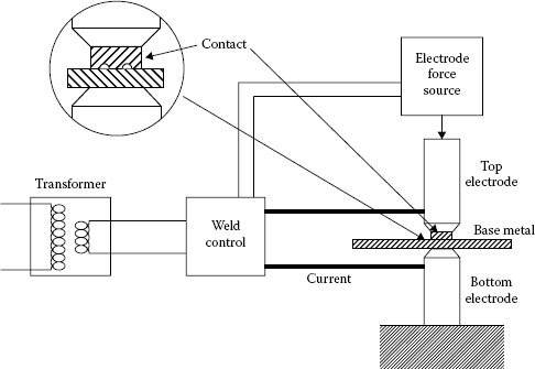
FIGURE 17.5
Illustration of a simple resistance welder.
Another area for clarification is the distinction between how the terms welding and brazing are differentiated in this chapter. Brazing processes are discussed in this chapter immediately following the sections on welding. The terms resistance welding, resistance brazing, spot welding, and spot brazing are often used interchangeably in the industry. A differentiation between welding and brazing is that brazing processes always employ the use of a filler metal which has a lower melting point than the components being joined. For the processes described in this section on welding, a filler metal may or may not be used depending on the contact material being attached. A resistance welding process as described in the following text can be technically described as a resistance brazing process when a filler metal is used. For the purpose of this chapter, the distinction between welding and brazing is based on process type rather than whether or not there is the use of a filler metal. For the processes where the term welding is used, the heating time is a fraction of a second and the attachment is for small to medium-size parts. The term brazing is used for processes for the attachment of medium to large parts that require longer heating times of several seconds to minutes for the liquefied brazing alloy to flow through the interface joint.
The welding of contacts onto backing material is more complicated than the riveting process. Resistance welding, which is the most popular welding method, involves controlling many parameters to obtain consistent weld bonds. The parameters for resistance welding include electrode materials, electrode shape, electrode surface condition, contact cleanliness, backing material cleanliness, electrode pressure, weld current control, and weld current timing. Many of these parameters are interrelated and changing one may require changing others. For example if the electrode material surface changes, the welding current, welding pressure, and timing may have to be changed. As a result of the more difficult control and the requirement of more sophisticated equipment it can be said that, in most cases, welding is more expensive than staking.
The bond area produced by welding depends on the type of welding being done. For resistance welding using a single projection on the back of the contact, see Figure 17.5, the bond is normally a little larger than the projection area. This typically is 25%–50% of the contact area. For resistance welding small contacts with full waffle backing bond areas from 70% to almost 100% are common. Welded designs in general have higher bond areas than staking designs.
Welded designs also offer an advantage over staked designs for applications where the device will see elevated temperatures. For welded designs the bond interface remains free from oxidation and is also not damaged by thermal cycling. It will also have more resistance to curling as described for rivets in Figure 17.2.
There are several types of welding methods that are used for making contact assemblies. A short description of these methods with pros and cons for each method is given below.
This type of welding refers to the attachment of individual contact disks, mostly called weld buttons, to a base metal carrier. Figure 17.6 shows some typical button designs. The buttons can be welded to a formed contact terminal or spring or the attachment can be made to the strip and the forming of the contact terminal or spring is done after attachment. The welding process for attachment of the contacts to the strip can be fully automated, for example the buttons can be fed from a feeder bowl onto a carrier strip which has pilot holes for locating the contacts. The strip is then fed from the welder onto a reel for later stamping and forming into a subassembly or into a punch press for immediate stamping and forming. This process has the advantage over clad strip in that the contact alloy is located only where it is needed.
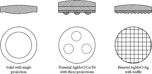
FIGURE 17.6
Typical designs for button types of contacts.
The buttons can have one or several projections which will limit the current and bonding to specific areas. This provides easier attachment if bond areas of less than 50% can be tolerated for the specific application. This method has the disadvantage that the bonded area is in the center of the part and there is no bonding at the circumference. In applications where the electrical erosion is significant this type of bond normally does not work since the edges of the contact pull up. This may result in welding of the contacts or in excessive erosion from thermal stress.
Buttons made with a waffle pattern rather than a projection offer a more uniform distribution of bonding between the contact and the backing. For this type of welding a higher current is required, because there is less of a current restriction at the interface compared to projection welding. This results in faster electrode wear. Welds made by this method can be used in applications where a long switching life is required and even though the erosion may be significant the contact will not peel from the backing.
Buttons made for this type of welding can be of either composite or solid construction. For silver metal oxides and silver refractory contacts, a weld layer made of fine silver or a brazing alloy is required to obtain a strong attachment. For fine silver, silver-nickel, and most of the silver-copper alloys, no weld layer is required.
This method is applicable to contacts, 2.5–7 mm in diameter. Contacts smaller than 2.5 mm become difficult to feed as individual contacts and contacts larger than 7 mm are more easily bonded by brazing or special welding processes which are discussed in a later section of this chapter.
Wire welding, as a method of making contact assemblies, has been used extensively in Europe for many years. One of the reasons is the heavy use of silver–nickel in many low-current AC applications. Silver-nickel can be welded directly onto copper alloys very easily. Automated machines for cutting silver–nickel wire, welding the wire to a strip, and coining the welded wire into a contact shape were developed in Europe and are used to make large volumes of contact assemblies for wiring devices, relays and industrial or commercial controls. These machines are not limited to welding silver nickel but any silver alloy that can be directly welded to copper or copper alloys. The advantage of this type of process is cost. The disadvantage of this design is again that there is no bond at the circumference of the contact interface with the backing. Another possible negative consideration for this process is that once you have invested in this type of welding equipment, you are limited to using only contact materials that can be directly bonded, which eliminates the use of popular contact alloys like silver metal oxides. This is one reason why this process is not as popular in the North America and Japan, where half the voltage and twice the current are used for many high volume applications. Here for the same application silver metal oxide contacts have to be used.
Another major option used for arcing contact design is contact tape, also called contact profiles. Contact tape construction is a possible option for any material that is ductile enough to be rolled or swaged into strip or wire. Contact tape consists of a laminated metal strip material with two or more metal layers laminated together. Figure 17.7 shows some different laminated structures. For contact welding tape, the top layer is always the contact material itself. The bottom layer is mostly a weldable alloy such as CuNi, Ni, Ag, CuAgP (“Silfos”), or other alloy that is directly weldable to a copper or copper alloy carrier. Besides having an alloy layer and weldable layer the tape can have a middle layer of copper. The purpose of this layer is to have a low cost, high conductivity filler that can be used to adjust the total thickness of the tape.
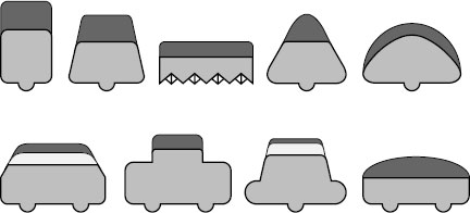
FIGURE 17.7
Typical designs for weld tape contacts.
Tape welding has the advantage over wire welding in that the weld layer can be made of a higher resistance material than the contact alloy and thus provide an optimum contact design for attachment. The tape can be made by several different methods. A common method is to make a wide sheet of laminated contact material by roll cladding. In this method a contact alloy and a base metal material in sheet form are fed into a rolling mill together and bonded during deformation. The pressure from the rolls forces the interface of the two materials to expand and create clean metal-to-metal contact bonding similar to that described earlier in this section for cold-bonded composite rivets. After the cladding the bimetal or trimetal sheets are slit into narrower tapes of the desired width and then formed into the desired weld tape or profile shape.
Another way that tape is made is to clad the strip materials in a width that is close to the width of the final tape. This type of cladding is done under higher temperatures which create diffusion bonding of the laminated layers. The finished tapes are often referred to as mini or micro profiles, depending on their physical size and shape.
In making tapes for some material combinations that may have trouble for developing good quality bonds it is possible to place a silver layer between the silver contact alloy and the bottom weldable alloy layer. This is a common practice for many silver metal oxide tapes. The weld layer of the tape may have weld rails or a waffle pattern to increase the current density at the weld interfaces. Weld rails are popular since they are easy to form during tape manufacturing and provide a uniform weld profile throughout a coil of tape. For welding tape the area of bonding is normally larger than the area of the weld rails. The percentage of bond needed for tape welding should depend on the current and life cycling required for a contact application. As the percentage of contact substrate interface area that is bonded increases, the life of the welding electrodes for the tape welding decreases. The reason for this is that higher current densities for the electrode and contact interfaces are needed for increasing the percentage of the contact-to-substrate interface bond. This relates directly to the cost of welding.
In comparing the cost of using tape contacts to rivet contacts, in general the cost of rivets is lower since staking requires no current and electrodes and results in less tooling wear. However, under certain conditions the cost advantage may favor tape welding. Some advantages for using tape are as follows:
1. If the contacts being used are very small, for example <2.2 mm in diameter, it becomes difficult to feed individual rivets with an automatic feeder bowl. This is not a problem for a continuous structure like tape for which machines have been developed for feeding and welding at speeds of over 200 parts per minutes.
2. For composite rivets the amount of contact alloy thickness that is used can only be decreased to a certain ratio of the contact head thickness, such as 40%–25%. For lower ratios beyond this limit the bonding between the silver based contact material and copper is decreased. For tape this ratio can be decreased much more resulting in lower contact material and silver use.
For bond quality, tape bonds can be evaluated by shear testing, ultrasonic scanning, and metallographic sectioning. Quite often a combination of methods is applied during initial equipment set-up and for process control purposes.
17.3.2 Special Welding Methods
Another type of welding that is used on a more limited basis is percussion welding [12]. This method can be used to directly weld materials like silver metal oxides onto a copper base metal with no intermediate layer. The method consists of using one or more small diameter projections, much smaller than used in projection welding, between the two components. The welding heating time is very short, typically one weld cycle at a very high current. The weld projection explodes and an arc is formed between the contact and backing. A high force is applied at the same time to the contact face, forcing the components together. During this short heating time there is no buildup of segregated metal oxide particles which will form when slower welding and brazing processes are used. The bonds, if the process is done correctly, have an area greater than 90% of the interface area. At the same time the very short heating cycle prevents the substrate materials from being softened by annealing.
The disadvantages of this process are the costs of the equipment, the necessary manual labor, and controlling weld flash that is expelled during the welding. The process requires special tooling for clamping the contact and backing during the welding. Even though the weld current application time is short, the total weld assembly cycle is long as a result of the time for clamping and unclamping. If the weld flash is not controlled well, additional expenses will result for removing the flash. This process is normally used for larger contacts of >8 mm diameter and for contact assembly designs that require high mechanical strength and stability. In general it is not competitive to other welding processes for smaller contacts which can more easily be automated or integrated into stamping operations for the contact supports.
17.3.2.2 Ultrasonic Welding of Contacts
Some experimental work has been done for ultrasonic welding of contacts [13]. Little information is available for this type of contact welding. The welding process can damage the contact material structure during the welding [13,14]. The process is also very sensitive to contact surface condition. This process can—in certain special instances and designs—produce good bond quality but has not developed as a popular production method for contacts since the process tends to damage the microstructure of many contact materials.
17.3.2.3 Friction Welding of Contacts
Friction welding is another process that is technically capable for welding some contact designs but has not been developed into a broader utilized manufacturing method. An example of how the process can be applied to a contact assembly is as follows: A silver metal oxide contact button is spun and then pushed against a copper contact carrier that is held stationary. The relative motion and force causes heating and plastic deformation at the weld interface that can result in a high-integrity solid-state bond [9]. The process has potential for minimizing both annealing of the carrier and formation of segregation of metal oxides which occurs when melting occurs during other welding processes. The process produces flash that must be controlled or removed. The economics and production practicality of this process for contact welding have remained limited to special low volume applications.
17.4 Brazed Contact Assembly Designs
For larger contact assemblies consisting of silver-based contact materials and predominantly copper alloy support carriers, brazing is employed as a traditional method of attachment [15]. The brazing processes discussed below all use silver based brazing alloys, sometimes also termed silver solders, as filler metals between the copper alloy carriers and the silver-based contact. The silver solders have a lower melting point than the contact or carrier, and this lowers the interface temperature required for fusion at the interface to take place. As discussed in Section 17.3, the brazing processes require much longer heating times than welding, seconds or minutes versus a fraction of a second, since time must be allowed for the brazing alloy to liquefy and flow through the whole joint.
The selection of the most suitable brazing alloys and methodology depends on the metallurgical and physical properties of the component materials, the geometry, bond requirements, hardness requirements, and economical considerations.
17.4.1 Methods for Brazing Individual Parts
Table 17.1 shows some of the common brazing methods used to attach medium- to large-size parts, 4 to over 80 mm in diameter. These processes mainly differ in the method used for application of the heat. For all of these processes the clearances between surfaces of the materials to be joined must closely match in order allow for capillary flow of the brazing alloy. Cleanliness of the surfaces is also important for all these processes. Parts are normally cleaned just before brazing. Except for furnace brazing the heating processes are normally done in air. Since all of these processes require long heating times compared to welding methods, oxidation can be significant and therefore some protective coatings such as fluxes are normally used. The flux can help in the wetting of the brazing alloy to the metals but it also generates gases that must be expelled from the braze joint. Some type of mechanical agitation of the contact being brazed is normally done during brazing to assist in gas removal. There are many choices for brazing alloys that can be utilized. Cadmium containing silver alloys were widely used in the past but have been replaced with Cd-free ones such as AgCuSn owing to the hazardous nature of cadmium. Some alloys that contain reducing components such as phosphorus can eliminate of the need for flux. For all of these processes the heating rate must be balanced in time and temperature for the attainment of good bonds without overheating the contact assembly, which can allow the brazing alloy to flow onto the contact face. For example, the alloys containing phosphorus wet the silver alloy so well that just a little overheating produces alloy flow onto the contact face. Brazing alloy on the contact face is a serious problem since it can cause mating contacts to stick or weld in service.
TABLE 17.1
Brazing Methods for Electrical Contacts
Method |
Heating Time |
Annealing Amount |
Productivity per Machine |
Tooling Cost |
Torch |
Minutes |
High |
High |
High |
Induction |
Many seconds |
Medium |
Medium |
Medium |
Direct Resistive |
Few seconds |
Low |
Medium |
Low |
Indirect Resistive |
Many seconds |
Medium |
Low |
Low |
Furnace |
Many minutes |
Complete |
High |
Medium |
This process is normally automated into a continuous process that can have high productivity. Since the actual torches are relatively inexpensive, several can be used on an index table or in line in different stations to heat up the part in steps. The heating time for this continuous process can be long, and as a result significant annealing of the contact carrier takes place. Since it is automated and uses many stations, the tooling costs can be significant.
Induction brazing can be automated into a continuous process, but since the induction units are expensive normally a semi-automated non-continuous process is used. The heat-up time is normally shorter than that for torch brazing since for non-continuous operations there is no long preheating step. The part is instead heated up as fast as possible to obtain alloy flow, and then the heat is turned off. Since the heating time is less with this process a lesser degree of annealing of the carrier takes place.
17.4.1.3 Direct and Indirect Resistance Brazing
This method has some similarity to the welding process described in Section 17.3. The major difference is that the heating of the contact assembly is mainly from heat generated in the electrode which is made of a lower conductivity material like graphite. The terms “direct” and “indirect” are used, since most of the resistance heating is transferred from the electrode to the contact assembly and only a small amount of resistance heating takes place directly in the interface joint. Some manufacturers refer to the term “Direct” for this process if force is applied directly to the contact assembly during the heating process which aids in degassing of the interface and thinning the interface melt layer. The heat is mainly generated in the joint interface and some annealing occurs from contact with the electrodes. Only one part can be done at a time but tooling is inexpensive. When using the term “Indirect” they refer to heating the contact support backing close to the contact tip location and letting the heat travel to the brazing interface. This quite often allows also some manipulation of the contact tips to expel flux induced gases generated during the heating. Depending on the assembly geometry sometimes two tips—for moving contact bridge assemblies for example—can be attached in one heat-up cycle. This indirect resistance process is however only suited for assemblies that can tolerate significant annealing of the support material or require anyhow secondary forming operations which re-harden the substrate backings.
For this type of brazing, a cover gas is normally used to prevent oxidation. For some alloys that do not contain metal oxides a reducing atmosphere can be used. A vacuum can also be used with proper controls and back filling with a cover gas to regulate the evaporation rate of the brazing alloy during melting. Fixtures made of graphite are commonly used to locate the braze components. The heating time is long, many minutes, so the parts are normally fully annealed after brazing. If many fixtures are made the productivity can be very high. Since a protective atmosphere is used no flux or only a light fluxing can be employed. Most of the contact structures used in vacuum interrupters are attached using this process.
17.4.1.5 Continuous Laminated Strip Brazing, “Toplay”
For larger quantity brazed contact assemblies, a continuous brazing process can be used, called “Toplay.” This brazing process is popular for making contact assemblies for small contactors and definite purpose relays. In this process the contact material in strip form and the copper carrier strip are fed into a small tube furnace with or without a brazing filler material. The furnace is designed to apply induction or resistance heating to the strip sandwich and also applies a force pushing the laminations together as the metal interface melts while moving through the tube furnace. A protective atmosphere can also be used to prevent oxidation. For example, with this process it is possible to braze small width silver metal oxide strips which have a silver backing directly onto copper strip by heating and applying pressure to the interface joint, forming a low melting silver–copper eutectic alloy at the interface, and cooling the interface in the last zone of the furnace while it is still under pressure. This results in a high percentage bond area which is almost void free. After the bonding step of this process the toplay laminated strip can be profile rolled to adjust the assembly thickness and restore some hardness to the materials. The last step in the process is to form the individual contact assemblies by stamping them in a progressive forming die.
17.4.1.6 Brazed Assembly Quality Control Methods
Braze joint quality is usually defined as a minimum percentage of the interface area being bonded and often also by a qualifying definition of the non-bonded void areas by size and/or distribution. Typical bond quality requirements are in the range of 70%–80% of the contact area above the interface even so for most arcing applications bond percentages above 50% do not influence the electrical life behavior. The actual braze area of brazed assemblies is much thicker than that for welded and cold formed bond designs. As a result it is easier to check for bond quality. Ultrasonic C-scans, X-ray, metallography, and shear testing can all be used to judge the quality and area of a bond.
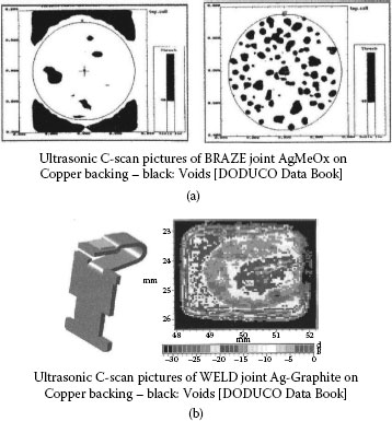
FIGURE 17.8
(a) Ultrasonic C-scan pictures of BRAZE joint AgMeOx on Copper backing—black: Voids and (b) Ultrasonic C-scan pictures of WELD joint Ag-Graphite on Copper backing.
As the example in Figure 17.8a shows, ultrasonic imaging can provide a clear indication of the true bond quality and the distribution of voids. Modern ultrasonic equipment with advanced software can also display the quality of weld joints as Figure 17.8b illustrates.
17.5 Clad Metals, Inlay, and Edge Lay
For some smaller low-current arcing contact applications and also non-arcing separable contacts clad metals in the form of inlay and edgelay are used (see Figure 17.9). Similar to the Toplay described in the previous section, the carrier strip has one or more contact alloy strips clad onto the carrier material [16]. These laminated structures can be made by roll cladding as described for tape above, seam welding, and special continuous brazing processes like Toplay. For smaller contact assemblies, e.g. 2–5 mm width contact alloy, this process offers an easy way for stamping companies to make a contact assembly. A problem with the method is that since the alloy is continuous on the carrier strip, often a large percentage of the alloy is wasted as skeleton scrap during the stamping process.
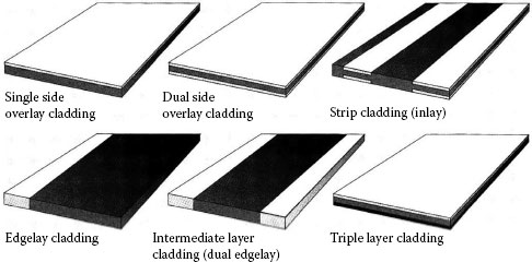
FIGURE 17.9
Typical configurations of clad contact strip materials. (From Doduco Data Book. Revised 3rd Edition, DODUCO GmbH-Stieglitz Verlag, Muehlacker, Germany, 2012 [16].)
17.6 Contact Alloys for Non-Arcing Separable Contacts
This section discusses gold contact alloys which are used in clad or electroplated composite structures for mainly non-arcing separable contact applications.
Historically gold is used for ornamental jewelry and coinage, because of its durability and resistance to environmental attack. For contact applications gold also combines high electrical conductivity with metallurgical properties that allow easy alloying with other metals. Its rarity and its link to the world’s monetary systems, however, have in the past influenced its declining usage mostly owing to economic considerations [17,18].
17.6.2 Manufacturing Technology
Gold in its high-purity form is rather soft and prone to mechanical wear. Alloying with metals such as copper, nickel and other precious metals by melting will enhance the physical properties while maintaining most of its superior chemical resistance properties. Gold and gold alloys can easily be clad to copper base substrate materials to form overlay and inlay strip material or weldable contact tapes from which contact components can be economically manufactured. Owing to their high ductility very thin layers of the contact material on the surface of suitable carriers can be applied by these methods. Mostly used in electronic connections, pure gold and thin deposits with minor property-enhancing additives are also applied by electroplating (see Chapter 8) for use in dry circuit and low-level switching contacts.
17.6.3 Physical and Chemical Properties
Table 24.6 in Chapter 24 gives typical data for the most commonly used gold contact materials as measured and reported in the literature [19,20] and by various contact manufacturers in handbooks, technical brochures, and data sheets [21,22,23]. They are typically obtained from measurements on wrought material samples produced under manufacturing conditions and represent average values or ranges for these materials as experienced under practical fabrication and use conditions. The material compositions are given following standard conventions with the alloying additives expressed as weight percent and the first element as main constituent representing the balance to 100% in weight.
The almost total chemical resistance of gold against reactions with surrounding atmospheric constituents under conditions experienced during its use as a switching, sliding or connector contact is its outstanding property. Gold oxide decomposes at low temperatures above 200°C and is not retained in a solidified melt produced under normal air atmosphere. The only reported chemical reactions occur when gold comes into contact with mercury forming an amalgam which ultimately can lead at temperatures above 400°C to the gold almost completely dissolving in the mercury [24]. Another reaction of practical importance is the attack of liquid lead and tin, mostly in the form of tin-lead solders, onto gold surfaces, leading to alloying and the formation of brittle phases.
Pure gold and also gold alloys will however easily adsorb organic molecules, often present from various plastic sources surrounding electrical contacts in modern miniaturized switches and relays. Some of these adsorbed films can then further react with the gold surface or the surrounding air atmosphere to form contact-degrading reaction films [25,26].
17.6.4 Metallurgical Properties
Alloying gold with different other metallic elements is done to alter both its mechanical and its electrical switching properties and at the same time reduce the content of this high-cost metal. Preserving the superior resistance to chemical attack while strictly improving its mechanical strength and hardness requires the addition of other precious or noble metals, in most cases resulting in more costly but highly reliable contact alloys such as the AuPt and AuPtAg materials, Table 24.6 and [21].
Adding up to 30 wt-% of silver to gold does little to increase its hardness and mechanical strength, but does lower the cost with little lowering of the alloy’s resistance to chemical attack. The two elements form a continuous series of solid solutions with the tendency of silver to the formation of silver sulfide showing a strong increase at higher silver contents. As a result, the alloy Au/Ag8 wt-% has gained widespread use as a contact material for dry circuit applications. To increase the mechanical stability the addition of copper to gold has practical limitations owing to the order–disorder transformations at typical annealing temperatures, which limit the cold workability of the resulting systems [27]. The binary alloy systems of gold-nickel and gold-cobalt exhibit a steep increase in mechanical strength and hardness at the low 2%–10% addition range which does not noticeably change the chemical resistance of gold. Cobalt is soluble in gold at higher temperatures for up to 8 wt-%, while at temperatures below 400°C the solubility drops to lower than 0.1%. This allows the precipitation hardening of higher percentage alloys which simultaneously in this heterogeneous condition have a substantially higher electrical conductivity, see Table 24.6 in Chapter 24. Tertiary alloy systems of gold with silver and copper or nickel have a lower electrical and thermal conductivity with low potential for surface oxidation and much higher values for hardness and mechanical strength. During the time of rapidly increasing commodity prices and fears of a reduced supply of gold in the early 1980s, other multi-component alloys on the basis of AuPd were developed and increasingly applied for telecommunication contacts.
17.6.5 Contact Applications and Performance
Pure gold finds only limited applications in electrical contacts owing to its softness and the resulting high mechanical wear and tendency to cold welding under even low mechanical forces. As a thin electroplated surface layer over other precious silver or palladium-based metal alloys pure gold is applied as a protective layer on high-reliability electronic connector components [28] (for examples see Chapter 8). Before the advent of electronic switching in telecommunication equipment, thin “gold flash” layers of typically 0.1–0.2 μm used to be the standard on silver contacts in small telephone relays, but this resulted in unexpected corrosion problems and thus is not a recommended practice. Continued usage for pure electroplated gold layers is still found today in high-reliability miniature relays by diffusing an electroplated gold layer into fine silver or silver alloy contacts with a post-plating heat treatment. A similar contact construction employing diffused gold is employed in reed relays with NiFe contact blades where the contacting ends of the plates are gold plated and undergo a heat treatment for controlled partial diffusion [20,29].
Gold with less than 1% alloying additives such as nickel and cobalt is widely used as an electroplated hard gold deposit in electronic connectors. Antler and Slade discuss these applications in more detail in Chapter 8, Materials, Coatings and Plating.
The authors thank Dr. Zhuan-Ke Chen, Chugai USA for his help with the figures. We thank Dr. Paul Slade for his discussions and suggestions. We also are grateful for the DODUCO GmbH to allow us to use some graphics from the latest edition of their Data Book on Electrical Contacts.
1. D Spaeth et al. “The Influence of the Bonding Area of Welded Contact Tips on Contact Erosion”, Proceedings of the 52nd IEEE Holm Conference on Electrical Contacts, 2006, pp. 181–287.
2. AS Janitzki and B Schaefer. “The Influence of the Quality of Brazing on the Erosion of Contacts”, Proceedings of the ICEC, IIT Chicago, IL, 1978, pp. 389–394.
3. Y Shen et al. “Peeling: A failure Mode of Arcing Contacts”, Proceedings of the 34th IEEE Holm Conference on Electrical Contacts, 1990, pp. 538–542.
4. ZK Chen and GJ Witter. “A Correlation of silver tin indium oxide-Copper Composite Rivet Interface Bond Quality and Switching Endurance Life in DC Relays”, Proceedings ICEC 2012, Beijing, China, May 2012, pp. 174–179.
5. ZK Chen and GJ Witter. “A Study of The Contact Endurance Switching Life as a Function of Contact Bond Quality, Electrical Load, and Residual Stresses for Composite Rivet Silver Tin Indium Oxide Contacts,” 58th IEEE Holm Conference on Electrical Contacts, Portland, OR, September 2012.
6. G Witter. Chugai USA, Inc., Waukegan, IL, Private Research.
7. Doduco Data Book. Revised 3rd Edition, DODUCO GmbH–Stieglitz Verlag, Muehlacker, Germany, 2012, pp. 131–138, 154.
8. R Nichting, D Olson, and G Edwards. “Low-temperature solid state bonding of copper”. J. Materials Engineering and Performance 1(1): 35–44, 1992.
9. American Society For Metals, ASM Handbook. Welding Brazing, and Soldering Vol 6. ASM Publications, Metals Park, OH, ISBN 0-87170-382-3, 1993.
10. American Society for Testing Materials. Unpublished Work of ASTM Committee B4.04 – Round Robin Testing, 1985.
11. G Witter. Chugai USA Inc. private observations.
12. Doduco Data Book, Op Cit, pp. 158–66.
13. D Stoeckel. “Ultrasonic Welding of Silver-Metal Oxide Contact Materials” (in German). Proceedings International Conference on Electrical Contacts, Tokyo, Japan, August 1976, pp. 321–326.
14. G Witter. Fansteel Inc., Waukegan,IL, private development work, 1983.
15. Doduco Data Book, Op Cit, pp. 155–157, 167–169, 177–180.
16. Doduco Data Book, Op Cit, pp. 146–153.
17. L Vigdor. The gold bullion market in the United States. Precious Metals 1988, Intl. Prec. Metal Institute, 1988, pp. 535–362.
18. CA Waine and PMA Sollars. A comparison of gold and alternative low cost finishes for connector applications. Proceedings 9th International Conference on Electrical Contact Phenomena, IIT Chicago, IL, 1978, pp. 159–171.
19. A Keil, WA Merl, and E Vinaricky. Elektrische Kontakte und ihre Werkstoffe. Berlin, Heidelberg, New York, Tokyo: Springer-Verlag, 1984.
20. D Stoeckel, et al. Werkstoffe fuer Elektrische Kontakte. Grafenau, Germany: Expert Verlag, 1980, p. 45.
21. Doduco Data Book, Op Cit, pp. 21–36.
22. K Pitney. Ney Contact Manual. Bloomfield, CT: J. M. Ney Company, 1973, pp. 68–79.
23. Electrical Contacts for Switching Applications, Advanced Metallurgy, Inc. Export.
24. RP Elliot. Constitution of Binary Alloys, First Supplement. New York: McGraw-Hill, 1965, p. 89.
25. VA Lavrenko et al. “The corrosion of gold and silver coated copper by the thermal degradation products of chloroprene and silicone rubber”. Corrosion Science 18: pp. 809–818, 1978.
26. G Horn. “The Influence of Vapors from Organic Insulating Materials on the Contact Resistance of Gold and Silver Alloys” (in German). Proceedings of the 7th International Conference on Electrical Contacts, Paris, 1974, pp. 72–79.
27. M Hansen. Constitution of Binary Alloys. New York: McGraw-Hill, 1958, pp. 198–203.
28. E Guancial et al. “Qualifications of connectors manufactured with diffused gold R156 inlay contacts”. Proceedings of 28th Holm Conference on Electrical Contacts, IIT Chicago, IL, 1982, pp. 43–52.
29. CA Haque. “Diffusion effects of the heat treatment of Au-Ag on Fe-Ni dry sealed reeds”. Proceedings of the 9th International Conference on Electrical Contact Phenomena. IIT, Chicago, IL, 1978, pp. 605–609.