
CONTENTS
20.2.4 Coefficient of Grounding
20.2.7 Insulation Resistance Discharge Voltage
20.3 Wave Shape and Rate of Rise
20.4 Operation of a Surge Arrestor
20.4.3 Metal Oxide Varistor (MOV)
20.5 Natural Lightning Strokes
20.8 Proper Connection of Arresters
20.8.3 Ground Resistance/Impedance
Distribution cable systems have peak failure rates during the summer months throughout North America. Research work has shown that impulse surges to cables shorten their service life [1,2]. Both temperature and rainfall may peak during the same time period. All of these factors may influence this failure rate. It is also well documented that water trees reduce the impulse level of extruded dielectric insulated cables and contribute to the failure situation. Most of the effort that has been spent in the past on lightning protection of distribution system components has been on overhead transformers. This is logical when you consider that the companies that build transformers are also the ones that sell arresters [3].
The older paper-insulated cables were manufactured with an inherently high impulse level and that level was maintained over the 50 plus years of life of the system. Today, the extruded dielectric insulated cables that are used so extensively in underground systems exhibit a dramatic drop in electrical strength in just a few months of service. It is important to note that cross-linked polyethylene (XLPE) cables start with a much higher impulse level than ethylene propylene (EPR) or paper cables. EPR cables have initial impulse strengths less than the others, but their impulse level does not drop as quickly and levels out. With time, both XLPE and EPR have impulse levels that are much nearer the basic impulse level (BIL) of the system than for paper cables. Because of this, lightning protection is a significant consideration for these newer cables.
This is defined as:
Another form of this equation for protective margin is:
A minimum protection margin of 20% over BIL is usually recommended for transformers.
Voltage rating of a metal oxide varistor (MOV) arrester is based on its duty-cycle test. The duty-cycle test defines the maximum permissible voltage that can be applied to an arrester and allow it to discharge its rated current. Another way to consider this is that it is the voltage level at which power follow-current can be interrupted after a surge discharge has taken place. At voltage levels above this, power follow-current interruption is doubtful. The safe arrester rating is usually determined by the highest power voltage that can appear from line to ground during unbalanced faults and shifting of the system ground [4–7].
The highest power voltage can be calculated by multiplying the maximum system line-to-line voltage by the coefficient of grounding at the point of arrester placement.
20.2.4 COEFFICIENT OF GROUNDING
This is defined as the ratio, expressed in percent, of the highest root mean square (rms) line-to-ground voltage on an unfaulted phase during a fault to ground. Systems have historically been referred to as being effectively grounded when the coefficient of grounding does not exceed 80%.
This refers to the initiation of the protective cycle that occurs when the surge voltage reaches the level at which an arc develops across the device’s electrodes to complete the discharge circuit to ground. In terms of voltage across gapped arresters, this is somewhat indefinite since sparkover of a simple gap structure is a function of both the wave front and the voltage of the incoming surge.
The essential requirement of a proper sparkover level is the speed of response to steep fronts, such as natural lightning, yet gives a consistent response to waves with slower rates of rise, which are typical of indirect strokes and system generated surges.
Sparkover of an arrester should not be confused with “flashover.” Flashover refers to the exterior arcing that may occur, for instance, when surfaces become contaminated.
Surge discharge refers to the situation where the arrester must handle the power frequency line current as well as the momentary surge current. This power follow-current continues to flow until the arrester can extinguish the arc.
20.2.7 INSULATION RESISTANCE DISCHARGE VOLTAGE
The insulation resistance (IR) discharge voltage of an arrester is the product of the discharge current and the resistance or inductance of the discharge path. While the resistance may be very low, the discharge current can be very high and the IR discharge voltage can reach levels that equal or exceed the arrester sparkover voltage. The inductance of the combined line and ground leads must be kept as short as possible. This is accomplished by placing the arrester as close as practical to the cable termination and always connecting the arrester closer to the incoming line than the termination (see Figure 20.5).
20.3 WAVE SHAPE AND RATE OF RISE
Natural lightning must be simulated in the laboratory to test and evaluate lightning protection devices and equipment. This is accomplished with a surge generator. A group of capacitors, spark gaps, and resistors are connected so that the capacitors are charged in parallel from a relatively low voltage source and then discharged in a series arrangement through the device being tested.
The terms used to describe both natural and artificial lightning are “wave shape” and “rise time” (Figures 20.1 and 20.2). The wave crest is the maximum value of voltage reached. Wave shape is expressed as a combination of the time from zero to crest value for the front of the wave and the time from zero to one-half crest of the wave tail. Both values of time are expressed in microseconds. The rate of rise is determined by the slope of a line drawn through points of 10% and 90% of crest value.
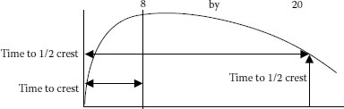
FIGURE 20.1 Wave shape.
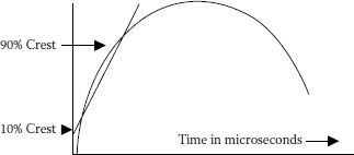
FIGURE 20.2 Rate of rise.
Testing of surge arresters has historically been done with an 8 × 20 microsecond wave, but more recent work has been done at 4 × 10 even though a direct stroke of natural lightning is nearly 1 × 1,000. See Figure 20.1 as to how these times are defined.
20.4 OPERATION OF A SURGE ARRESTOR
The original surge arrester was a simple air gap. They were made of a simple rod or spheres installed between the line and the ground that were far enough apart to keep the line voltage from sparking over but close enough to discharge when a surge occurred. Air gaps have the disadvantage of allowing system short circuit current to continue to flow until the breaker, fuse, or other backup device operates.
Air gaps have another disadvantage. Electrically speaking, they are sluggish and their response varies as stated above. Sparkover may not occur until a considerable portion of a rapidly rising lightning surge has been impressed on the system. The short gap spacing necessary to provide adequate protection against steep front lightning waves may result in frequent and unnecessary sparkovers on minor power frequency disturbances.
Nonlinear resistance can best be considered as resistance that varies inversely with applied voltage (Figure 20.3). Under normal voltage conditions, the resistance is high; under unusual high voltages, the resistance is low.
The material that, in the past, has been used extensively in valve arresters is silicon carbide. It is blended with a ceramic binder, pressed into blocks under high pressure, and fired in kilns at temperatures of over 2,000°F. This component is the valve block. The number of valve blocks used in an arrester is determined by resistance requirements for the rating of the system.
For silicon carbide blocks, it is essential that an air gap be in series with the blocks since they would conduct a large amount of current at operating voltage. This gap must ionize the atmosphere in the arc chamber to break down that gap before the blocks encounter any voltage. After the air gap breaks down, the valve blocks begin to conduct the combination of surge current and power current. The high voltage of the lightning surge decreases the resistance of the valve blocks and the current flows to ground. The voltage now across the blocks is approximately the line-to-ground voltage of the system. The valve blocks revert to their normal high resistance. This forces the power flow current to be reduced to a value that the series blocks can interrupt at the next system current zero.
20.4.3 METAL OXIDE VARISTOR (MOV)
MOVs (variable resistors) became available for distribution systems in 1978. Their first use on distribution systems was on terminal poles, hence the term riser pole arrester.
Gaps are not required because the material is extremely nonlinear. The lower half of the schematic shown in Figure 20.4 represents a MOV arrester. A voltage increase of just over 50% results in a conduction current change of 1 to 100,000. The absence of gaps allows these devices to operate much faster than the older gapped silicon carbide arresters. The absence of gaps is a major factor in allowing MOVs to be used in load break elbow arresters.
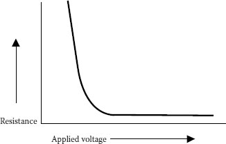
FIGURE 20.3 Nonlinear resistance.
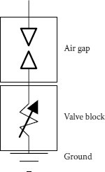
FIGURE 20.4 Schematic of a silicon carbide arrester.
Grounding resistance/impedance must be treated more seriously now that the underground residential distribution (URD) systems are using conduit and/or jacketed neutral wires. With bare neutral wires, the stroke energy was dissipated along the cable run. The insulation provided by the jacket or conduit makes low resistance grounds at the terminals an essential factor. Customer’s grounds helped older systems have low resistance before those pipes became plastic. Even gas pipes are now plastic!
20.5 NATURAL LIGHTNING STROKES
The understanding of natural lightning has increased tremendously since the early 1980s. Electric Power Research Institute (EPRI) efforts led to the construction of antennas throughout the US, and beyond, to record lightning strokes. These systems are now capable of pinpointing the time, location, magnitude, and polarity of strokes that occur between the clouds and the ground. What has been determined is that the rate of rise and the current magnitudes of natural lightning are much more severe than previously assumed.
From this information, we now have recorded strokes of over 500,000 amperes. Although these high stroke currents do occur, examination of arresters removed from service do not show that they have discharged such high values of current. One possible explanation is the division of stroke currents into multiple paths. Another is that the majority of strokes terminate to buildings, trees, or the ground without directly striking the electrical system. Recent research indicates that indirect strokes may be the biggest cause of failures on today’s distribution systems.
Rate of rise is extremely important because the faster the rate, the higher the discharge voltage will be for all types of arresters. Recorded data shows that natural lightning strokes have rise times between 0.1 and 30 μs with 17% of the recorded strokes having rise times of 1 μs or faster and 50% are less than 2.5 μs. For the same wave shape, the average rate of rise increases with the crest magnitude. Using the “standard” 8 × 20 microsecond wave and a 9 kV-gapped arrester, the discharge voltage is about 40 kV. For the same 20 kA stroke but rising to crest in 1 microsecond, the arrester would have a 54.4 kV discharge or a 36% increase. Metal oxide arresters (without gaps, of course) commonly exhibit a 12% to 29% increase under similar circumstances.
The inductance (hence, length and shape) of the arrester leads becomes more pronounced with the faster rate of rise. Applying the generally used value of 0.4 microhenries per foot, the lead voltage is 8 kV per foot of total lead length at 20 kA per microsecond and 16 kV per foot at 40 kA. Assuming new arresters and 2 feet of total lead length, the total voltage at 20 kA and 40 kA would be 70 and 96 kV, respectively. In other words, a stroke having a 40 kA per microsecond rate of rise would add 32 kV to the arrester discharge voltage given in a typical manufacturer’s literature.
Prudent engineering suggests that the level of protection should be calculated for a family of possible values of current and rates of rise for the anticipated lightning activity in the service area under study. This suggests currents such as 40 kA for parts of central Florida, but only 10 kA or lower for California. Rates of rise of 1 to 3 microseconds are commonly used in calculations.
For an interesting note, these systems are of use to many organizations. Lightning stroke information is used by the forest service to warn of fires rather than the old fire towers or airplanes. Antennas near Anchorage, Alaska, warn of volcanic eruptions that produce lightning.
Whenever a lightning stroke encounters an electric system, energy is propagated along the circuit from the point of origin in the form of a traveling wave. The current in the wave is equal to the voltage divided by the surge impedance of the circuit. Surge impedance is approximately equal to the square root of the ratio of the self-inductance to the capacitance to ground of the circuit. Both the inductance and capacitance are values per given unit length making the surge impedance of a circuit independent of the actual length of the circuit.
A traveling wave will keep moving without change in a circuit of uniform surge impedance except for the effects of attenuation. As soon as the wave reaches a point of change in impedance, reflections occur.
A wave reaching an open circuit is reflected without change in shape or polarity. The resultant voltage at the open end will be the vector sum of the incident wave and the reflected wave. This is the source of the voltage doubling circumstance. If an arrester is located at the open point, this doubling does not occur after the arrester begins to discharge.
When a wave arrives at a ground or other value of impedance that is lower than the surge impedance of the circuit, the incident wave is reflected without change in shape but with a reversal in polarity.
No reflections will occur on a circuit that is connected to ground through a resistance/impedance that is equal to the surge impedance of the circuit since there is no change in impedance.
It is convenient to think of traveling waves as having square shapes to illustrate the points just mentioned, but since real surges have a finite time to crest, the results of the superposition of the actual wave shapes are quite different than the square waves, which are the worst-case scenarios.
For practical purposes, a traveling wave on an overhead line travels at the speed of light—984 feet per microsecond. The velocity of propagation of a traveling wave in cables commonly used today is about half the speed of light, or 500 to 600 feet per microsecond. This can be derived from the fact that, in an insulated and shielded cable, the speed is reduced depending on the specific inductive capacity, or permittivity, of the insulating material.
(20.1) |
This calculates out to 659 ft/μsec for tree-retardant cross-linked polyethylene (TR-XLPE) and 577 ft/μsec for an EPR. The use of time domain reflectometry (TDR and also known as “radar”) for finding faults, neutral corrosion, and so forth, uses this velocity to locate the problem. A reasonably accurate location will be obtained using this formula, but it must be noted that there are other factors involved such as the type of shield. A cable with a longitudinally corrugated shield will have a velocity of propagation that is slightly slower than what would be calculated using Equation 20.1, for instance. A cable with an overlapped flat tape shield that has corroded may slow the time down by several percentage points or be so severe that the wave is so greatly attenuated that it never reflects back to the sending point.
Velocity of propagation becomes important to the protection of distribution cables because the travel time from the junction arrester to the end of the cable run is very short as compared with the conduction time of the arrester. Consider a typical 5,000-feet long loop that is open at the midpoint. At 500 feet per microsecond, the travel time is only 5 microseconds to the end and 10 microseconds for the round trip. The arrester conduction time for an 8 × 20 microsecond wave is about 50 microseconds. This means that the junction arrester still has 90% of its conduction time left when the wave has traveled to the end of the cable. If the end does not have an arrester, the reflected wave will travel back toward the junction point and add to the incoming voltage wave throughout the length of the cable. Thus, the entire cable is exposed to the “doubled” wave. The amount of time the incoming wave is maintained becomes an important consideration as to the exposure of the cable to this full doubling of voltage.
Attenuation due to losses in the insulation has a negligible effect on the reflected voltage because the low loss insulations that are in use today do not attenuate the wave appreciably in the relatively short runs used for distribution systems. Attenuation due to shield type and configuration can be a serious problem. Helically applied flat tapes can deteriorate and corrode to the point that for a pulse having a fast rate of rise, the shield system looks like an open spiral. A TDR pulse cannot travel very far without being attenuated to unreadable levels. The good thing about this fact is that a time domain reflectometry (TDR) pulse can be used to find open shields as well as alert the user to limitations on what method of assessment testing can be utilized.
20.8 PROPER CONNECTION OF ARRESTERS
There are several extremely important installation rules for arresters:
• Keep both the line and ground side leads as short and straight as possible. (It is the sum of the two lead lengths that must be used in the calculations.)
• The lead from the line should go to the arrester FIRST—then to the termination.
• The ground resistance should be as low as practical. This means 10 ohms if the cable has an insulating jacket or is in a conduit.
The issue of lead length on the voltage that will be impressed on a cable has been discussed earlier in this chapter. All of that is correct. There is, however, one more issue here. Does that lead carry the lightning current? If the lightning current flows in that lead, its length is a factor. If, on the other hand, the lead does not carry lightning current, its length and impedance are not factors. In the real world, the current generally flows through all the paths that are available. The amount of current times the length of each lead establishes the voltage that is impressed on the cable. The practical point is that the circuit must be analyzed in its entirety, which includes both the hot lead and the ground lead.
In the beginning of this section, it was stated that the lead from the incoming line should first be attached to the arrester—then to the termination. Wait a minute. This is not the way we have always done it! Are you certain of that?
Yes. If we can visualize the flow of lightning current as a flood of water, we can easily recognize that we would be much better off if we could divert that flood around our house—not through it. That is why the arrester is the first connection point. The bulk of the current flows through the arrester to and through its ground. The termination lead length is not very significant because it is not carrying that much current.
20.8.3 GROUND RESISTANCE/IMPEDANCE
Why is the ground resistance/impedance important? We are concerned about voltage, and voltage is the product of current and impedance (length). Almost all of the current that goes through the arrester must flow to the ground at the arrester location. Remember that the impedance of an overhead line (the neutral for our purposes) is about 50 to 60 ohms. If the ground at the arrester is very high, then all of that lightning current must flow along those neutrals. This means that the “footing” resistance is 60 ohms. The voltage that is developed is the current multiplied by 60 ohms. Even if there are two directions for the ground current to flow, this can be a very high voltage.
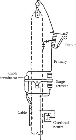
FIGURE 20.5 Correct arrester connection diagram.
The voltage buildup through the arrester is increased by the voltage buildup in the ground circuit (Figure 20.5).
1. Underground Distribution System Design and Installation Guide, NRECA, 1993, Section 5.
2. “Effect of Voltage Surges on Solid Dielectric Cable Life”, EPRI 6902-1990.
3. “Surge Behavior of URD Cable Systems”, EPRI EL-720, April 1978.
4. Westrum, A. C., 1979, “State of the Art in Distribution Arresters”, Thirty-Second Annual Time to 1/2 Crest Power Distribution Conference, University of Texas–Austin.
5. Hopkinson, R. H., 1983, “Better Surge Protection Increases Cable Life”, Electric Forum.
6. Sakshaugh, E. C., 1977, “Influence of Rate of Rise on Distribution Arrester Protective Capability”, Electric Forum.
7. Lightning Protection for Rural Electric Systems, 1993, NRECA Pub. #92-12.