
CONTENTS
2.2 Electric Fields and Voltage
2.7 Conductor Shield is Needed
2.8 Shielding Layer Requirements
2.9 Insulation Layer Requirements
2.11.1 Nonshielded Power Cable
2.11.2 Medium Voltage Shielded Cables
2.11.4 Electrical Insulation (Dielectric)
Whether being used to convey electric power or signals, it is the purpose of a wire or cable to convey the electric current to the intended device or location [1]. In order to accomplish this, a conductor is provided, which is adequate to convey the imposed electric current. Equally important is the need to keep the current from flowing in unintended paths rather than the conductor provided. Electrical insulation (dielectric) is provided to largely isolate the conductor from other paths or surfaces through which the current might flow. Therefore, it may be said that any conductor conveying electric signals or power is an insulated conductor.
2.2 ELECTRIC FIELDS AND VOLTAGE
Current flow is charge in motion. We might consider the simple case of a conductor carrying current out to a load and then a return conductor as two separate parallel cylinders of charge. If we neglect the conductor diameter (line of charge), there are electric field lines represented by circles of diameters such that the center of the circles are on the “0” line and each circle passes through the center of the cylinders. Everywhere perpendicular to the electric field lines are equipotential (equal voltage) lines due to each charge. The voltage at any location is the sum of the voltages due to each charge. Since the circle centers lie on the straight line equally distant from the charges, the equipotential lines from each charge exactly cancel on this line and the net voltage is “0” (see Figure 2.1).
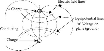
FIGURE 2.1 Electric field lines and equipotential lines for two lines of charge or a line of charge above a conducting plane.
If the “0” voltage line is now replaced with a conducting plane (such as the earth) and only the conductor above the plane remains, the locations of the electric field lines and equipotential lines are not changed. However, the portion below the “0” voltage line is simply an image of that above the line (method of images). This then, neglecting the conductor diameter, represents the electric field lines and equipotential (equal voltage lines) lines for an energized, current carrying conductor above ground. Of course, in this case the insulation (dielectric) is air.
A metallic conductor suspended from insulating supports, surrounded by air, and carrying electric signals or power may be considered as the simplest case of an insulated conductor. It also presents an opportunity to easily visualize the parameters involved.
In Figure 2.2, the voltage is between the conductor and the ground [2,3], where the ground is at “0” potential as shown in Figure 2.1. The charge separation between the conductor and the ground, results in a capacitor and because there is some (generally very small) conduction from the conductor to the ground, a large resistance also exists between the conductor and the ground. As long as the ground is well away from the conductor, the electric field lines leave the conductor outer surface as reasonably straight lines emanating from the center of the conductor. We know that all the electric field lines bend to ultimately terminate at ground (see Figure 2.1).
Air is not a very good insulating material since it has a lower voltage breakdown strength than many other insulating materials. It is low in cost and if space is not a constraint, then it is a widely used dielectric. As the voltage between the conductor and the ground is increased, a point is reached where the electric stress at the conductor exceeds the voltage breakdown strength of air. At this point, the air literally breaks down producing a layer of ionized, conducting air surrounding the conductor. The term for this is corona. It represents power loss and can cause interference to radio, TV, and other signals. It is not uncommon for this condition to appear at isolated spots where a rough burr appears on the conductor or at a connector. This is simply because the electric stress is locally increased by the sharpness of the irregularity or protrusion from the conductor. In air or other gasses, the effect of the ionized gas layer surrounding the conductor is to increase the electrical diameter of the conductor to a point where the air beyond the ionized boundary is no longer stressed to breakdown at the prevailing temperature, pressure, and humidity. This ionized air might be considered as an unintentional conductor shield. The unlimited supply of fresh air and the conditions just mentioned preclude the progression of the ionization of air all the way to the ground. It is possible that the stress level is so high that an ionized channel can breach the entire gap between the conductor and the earth, but this generally requires a very high voltage source such as lightning.
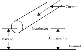
FIGURE 2.2 Location of voltage and current.
This raises another important fact about dielectrics: that is, their ability to not break down under voltage is thickness dependent. In Chapter 6, the breakdown strength of air is given as 79 V for a 1/1,000 inch (1 mil) thickness (3.1 kV/mm). However, as thickness increases, the breakdown strength does not increase proportionately. If it did, a case could be made that lightning could not occur in the usual case.
Space is a common constraint that precludes the use of air as an insulator. Imagine the space requirements to wire a house or apartment using bare conductors on supports with air as the insulation. Let us consider the next step where some of the air surrounding the previous conductor is replaced with a better insulating material (dielectric).
In Figure 2.3, we see that the voltage from the conductor to the ground is the same as before. A voltage divider that is made up of impedance from the conductor to the outside covering surface and also impedance from the covering surface to the ground has been created. The distribution of voltage from the conductor to the covering surface and from the covering surface to the ground will be in proportion to these impedances. It is important to note that with ground relatively far away from the covered conductor, the majority of the voltage exists from the covering surface to the ground. Putting this in another way, the outer surface of the covering has a voltage that is within a few percent of the voltage on the conductor (95% to 97% is a common value).
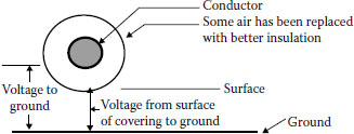
FIGURE 2.3 “Covered” conductor.
The amount of current that can flow from an intact covering to the ground in the event of contact by a grounded object is limited by the thickness, dielectric constant, and surface impedance of the covering as well as the area of contact. If the covering is made of an excellent insulation, the majority of the current will be due to capacitive charging current, which can be released from the covering surface by the contacting object.
So little current is available at the covering surface of a low voltage cable (600 V or less), which is imperceptible. When this condition exists with some level of confidence, the “covering” is then considered to be “insulation” and suitable for continuous contact by a grounded surface as long as such contact does not result in chemical or thermal degradation. The question arises as to what is considered to be low voltage. The voltage rating of insulated cables is based on the phase-to-phase voltage. Low voltage is generally considered to be less than 600 V phase-to-phase (1 kV is also common internationally). See Chapters 4 and 9 for additional information.
Because of the proximity and contact with other objects, the thickness of insulating materials used for low voltage cables is generally based on mechanical rather than electrical requirements. The surrounding environment, the need for special properties such as sunlight, or flame resistance, and rigors of installation often make it difficult for a single material to satisfy all related requirements. Designs involving two or more layers are commonly used in low voltage cable designs. The outer layer, though commonly insulating, may sacrifice some of the insulating quality to achieve toughness, sunlight resistance, flame resistance, chemical resistance, and more. In this case, the outer layer may serve as both insulation and jacket.
Return to the metallic conductor that is covered with an insulating material and suspended in air. When the ground plane is brought close or touches the covering, the electric field lines, as depicted in Figure 2.1, must bend more sharply to terminate at right angles to the ground plane.
In Figure 2.4, we see considerable bending of the electric field lines. Recognizing that equipotential lines are perpendicular to the field lines, the bending results in potential differences on the covering surface. At low voltages, the effect is negligible. As the voltage increases, the point is reached where the potential gradients are sufficient to cause the current to flow across the surface of the covering. This is commonly known as “tracking.” Even though the currents are small, the high surface resistance causes heating to take place, which ultimately damages the covering. If this condition is allowed to continue, the erosion may progress to significant covering damage, and, if in contact with the ground, results in failure.
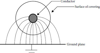
FIGURE 2.4 Electric field lines bend to terminate at ground plane.
It is important to note that the utilization of spacer cable systems and heavy walled tree wires depends on this ability of the covering to reduce current flow to a minimum. When sustained contact with branches, limbs, or other objects occurs, damage may result with time—hence such contacts may not be left permanently, but must be removed from the cable periodically as a maintenance practice.
At first, it might be thought that the solution is to continuously increase the insulating covering thickness as the operating voltage increases. Cost and complications involved in overcoming this difficulty would make this a desirable first choice. Unfortunately, breakdown strength, surface erosion, and personnel hazards are not linear functions of voltage versus thickness and this approach becomes impractical.
In Figure 2.1, imagine that the ground plane was “wrapped” around the conductor with the same thickness of air separating the two. Barring surface irregularities at the conductor or ground, the electric field lines would be straight lines taking the shortest path from the conductor to the ground and the equipotential lines would be concentric cylinders around the conductor. This would form a cylindrical capacitor and would make the most effective use of the dielectric.
In order to make this ground contact possible, a semiconducting or resistive layer may be placed over the insulation surface. This material forces the bending of the field lines in the semiconducting layer. This layer creates some complications, however.
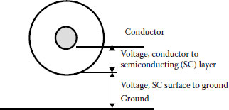
FIGURE 2.5 Conductor with insulation and insulation shield.
In Figure 2.5, it is clear that a cylindrical capacitor has been created from the conductor to the surface of the semiconducting layer, and a noncylindrical capacitor from the semiconducting layer to ground. A great deal of charge can be contained in the capacitor involving the ground because the outer plate is semiconducting, allowing for greater charge mobility in the layer. This charging current must be controlled so that a path to the ground is not established along the surface of the semiconducting layer. This path can lead to burning and ultimate failure of that layer. Accidental human contact would be a very serious event. It is clearly necessary to provide a continuous contact with the ground, which provides an adequate conducting path to drain the capacitive charging current to the ground without damage to the cable. This is done by adding a metallic path in contact with the semiconducting shield and making a relatively low resistance connection to the ground.
Once a metallic member has been added to the shield system, there is simply no way to avoid its presence underground fault conditions. This must be considered by providing either adequate conductive capacity in the shield to handle the fault currents or supplemental means to accomplish this. This is a critical factor in cable design.
Electric utility cables have fault current requirements that are sufficiently large that it is common to provide for a neutral in the design of the metallic shield. These cables have been known as underground residential distribution (URD) and underground distribution (UD) style cables. It is important that the functions of the metallic shield system are understood, since many serious errors and accidents have occurred because the functions were misunderstood.
2.7 CONDUCTOR SHIELD IS NEEDED
The presence of an insulation shield creates another complication. The grounded insulation shield results in the entire voltage stress being placed across the insulation.
Just as in the case of the air-insulated conductor, there is concern about exceeding the maximum stress that the insulating layer can withstand. The problem is magnified by stranded conductors or burrs and scratches that may be present in both stranded and solid conductors.
In Figure 2.6, a semiconducting layer has been added over the conductor to smooth out any irregularities. This reduces the probability of protrusions into the insulating layer. Protrusions into the insulation or into the semiconducting layer increase the localized stress (stress enhancement) that may exceed the long-term breakdown strength of the insulation. This is especially critical in the case of extruded dielectric insulations. Unlike air, there can be no fresh supply of insulation. Any damage will be progressive and lead to total breakdown of the insulating layer. There will be more discussion about “treeing” in Chapters 6 and 19.
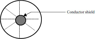
FIGURE 2.6 A conductor shield is added to provide a smooth inner electrode.
2.8 SHIELDING LAYER REQUIREMENTS
There are certain requirements inherent in shielding layers to reduce stress enhancement. First, protrusions, whether by material smoothness or manufacturing, must be minimized. Such protrusions defeat the very purpose of a shield by enhancing electrical stress. The insulation’s shield layer has a further complication in that it is desirable to have it easily removable to facilitate splicing and terminating. This certainly is the case at medium voltage (5 to 35 kV). At higher voltages, the inconveniences of a bonded insulation shield can be tolerated to gain the additional probability of a smooth, void-free insulation–insulation shield interface for cables with a bonded shield.
2.9 INSULATION LAYER REQUIREMENTS
At medium and higher voltages, it is critical that both the insulation and insulation-shield interfaces be contamination free. Contamination at the interface results in stress enhancement just as a protrusion that can increase the probability of breakdown. Voids can do the same with the additional possibility of capacitive–resistive (CR) discharges in the gas-filled void as voltage gradients appear across the void. Such discharges can be destructive of the surrounding insulating material and lead to progressive deterioration and breakdown.
In low voltage applications, jackets are commonly used to protect the underlying layers from physical abuse, sunlight, flame, or chemical attack. In medium voltage shielded cables, chemical attack includes corrosion of underlying metallic layers for shielding and armoring. In multiconductor designs, overall jackets are common for the same purposes. For medium and high voltage cables, jackets have been almost universally used throughout the history of cable designs. They are used for the same purposes as for low voltage cables, with special emphasis on protecting the underlying metallic components from corrosion. The only exceptions were paper-insulated, lead-covered cables and early URD/UD designs that were widely used by the electric utility industry. Both “experiments” were based on the assumption that lead, and subsequently copper wires, was not subject to significant corrosion. Both experiments resulted in elevated failure rates for these designs. Jackets are presently used for these designs. The ability of the jackets to reduce the ingress of moisture, which has been shown to have a deleterious effect on most dielectrics, causes them to be mentioned here.
To better understand the terminology that is used throughout this book, a brief introduction of the terms follows.
2.11.1 NONSHIELDED POWER CABLE
A nonshielded cable may consist of one or several conductors and one or several insulating layers. The cable may contain a jacket. The cable may also include a conductor shield. A cable is not considered fully shielded until both conductor and insulation shields are present. In the USA, nonshielded cables are common in the 0 to 2 kV voltage range although nonshielded power cables through 5 kV were common in the past and as high as 8 kV have been available.
2.11.2 MEDIUM VOLTAGE SHIELDED CABLES
Medium voltage cables generally are fully shielded (having both conductor and insulation shields) cables in the 5 kV (6 kV internationally) through 35 kV (30 kV internationally) voltage range.
Conductors may be solid or stranded. Metals used are commonly copper or aluminum. An attempt to use sodium was short-lived. The strand can be concentric, compressed, compacted, segmental, or annular to achieve desired properties of flexibility, diameter, and current density. The introduction of steel strands, higher strength aluminum alloys, hard drawn copper, Alumoweld, and Copperweld is common in overhead applications requiring greater tensile strength or other applications with the same requirements.
Assuming the same cross-sectional area of the conductor, there is a difference in the diameters between solid and various stranded conductors. This diameter differential is an important consideration in selecting the methods to effect joints, terminations, and fill of conduits.
Conductors are covered in Chapter 3.
2.11.4 ELECTRICAL INSULATION (DIELECTRIC)
The insulation (dielectric) provides sufficient separation between the conductor and the nearest electrical ground to adjacent phase to preclude dielectric failure. For low voltage cables, the required thickness of insulation to physically protect the conductor is more than adequate for the required dielectric strength.
Emphasis will be on 60 Hz alternating current fields (50 Hz is more common internationally). In all cables, regardless of their kilovolt ratings, there exists an electric field whenever the conductor is energized. This electric field can be visualized as electric field lines and lines of equipotential (see Figure 2.1).
Equipotential lines represent points of equal potential difference between electrodes having different electrical potentials.
1. Landinger, C. C., 2001, adapted from class notes for “Understanding Power Cable Characteristics and Applications,” University of Wisconsin–Madison.
2. Clapp, A., Landinger, C. C., and Thue, W. A., September 15–20, 1996, “Design and Application of Aerial Systems Using Insulating and Covered Wire and Cable,” Proceedings of the 1996 IEEE/PES Transmission and Distribution Conference, 96CH35968, Los Angeles, CA.
3. Clapp, A., Landinger, C. C., and Thue, W. A., September 15–20, 1996, “Safety Considerations of Aerial Systems Using Insulating and Covered Wire and Cable,” Proceedings of the 1996 IEEE/PES Transmission and Distribution Conference, 96CH35968, Los Angeles, CA.