
Chapter 16
Mastering Your Multimeter to Measure Circuits
IN THIS CHAPTER
![]() Introducing your new best friend: your multimeter
Introducing your new best friend: your multimeter
![]() Using a multimeter to measure all kinds of things
Using a multimeter to measure all kinds of things
![]() Setting up and calibrating your multimeter
Setting up and calibrating your multimeter
![]() Making sure electronic components are working properly
Making sure electronic components are working properly
![]() Probing around your circuits
Probing around your circuits
![]() Identifying the cause of circuit problems
Identifying the cause of circuit problems
Your excitement builds as you put the finishing touches on your circuit. With close friends standing beside you, eager to witness the first of your ingenious electronics exploits, you hold your breath as you flip the power switch, and …
Nothing. At least, nothing at first. Then, disappointment, disillusionment, and disbelief as your friends — and your confidence — slowly retreat from the scene.
You ask yourself, “What could possibly be wrong?” Then you notice it: Smoke is emanating from what used to be a resistor. And then you realize that you used a 10 Ω resistor instead of a 10 kΩ resistor, trusting your weary eyes and mind to read and interpret resistor stripes properly. Oops!
In this chapter, you find out how to use a versatile tool — the multimeter — to perform important face-saving checks on electronic circuits and components. These tests help you determine whether everything is A-OK before you start showing off your circuitry to friends and family. When you’ve finished reading this chapter, you will realize that your multimeter is as important to you as an oxygen tank is to a scuba diver: You can both get along okay on your own for a while, but sooner or later, you’re bound to suffer unless you get some help.
Multitasking with a Multimeter
A multimeter is an inexpensive handheld testing device that can measure voltage, current, and resistance. Some can also test diodes, capacitors, and transistors. With this one handy tool, you can verify proper voltages, test whether you have a short circuit, determine whether there’s a break in a wire or connection, and much more. Make friends with your multimeter, because it can help you make sure your circuits work properly and is an invaluable tool for scouting out circuit problems.
Figure 16-1 shows a typical midpriced multimeter. You turn a dial to select the type of measurement you want to make. You then apply the metal tips of the two test leads (one red, one black) to a component or some part of your circuit, and the multimeter displays the resulting measurement.
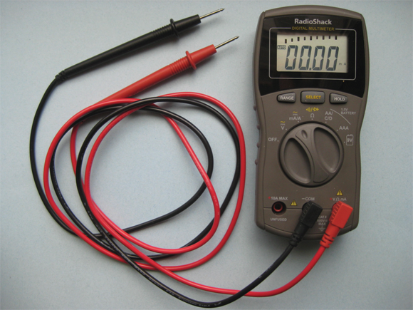
FIGURE 16-1: Multimeters measure voltage, resistance, current, and continuity.
 Multimeter test leads have conical tips that you hold in contact with the component you’re testing. You can purchase special spring-loaded test clips that slip over the tips, making it easier for you to attach the test leads to the component leads or other wires. (See Figure 16-2.) These insulated test clips ensure a good connection between the test leads and whatever it is you’re testing, while preventing accidental contact with another part of the circuit.

FIGURE 16-2: Spring-loaded test clips prevent accidental contact.
It’s a voltmeter!
Multimeters can measure both DC and AC voltages, providing a variety of voltage measurement ranges, from 0 volts to a maximum voltage. A typical set of DC voltage ranges is 0–0.25 V, 0–2.5 V, 0–10 V, 0–50 V, and 0–250 V.
Using your multimeter as a voltmeter, you can measure the voltage of a battery outside a circuit or under load (meaning when it is providing power in a circuit). You can also use your multimeter with your circuit powered up if you want to test voltages dropped across circuit elements and (for that matter) voltages at various points in your circuit with respect to ground.
You can often pinpoint the location of a problem in your circuit by using your multimeter. It can verify whether the proper voltage is supplied to a component, such as a light-emitting diode (LED) or a switch. You use multimeter tests to narrow the field of suspects until you find the culprit causing all your headaches.
Voltmeters are so important in electronics, they have their own circuit symbol, which is shown in Figure 16-3, left. You may see this symbol with leads touching points in a circuit you read about on a website or in an electronics book. It tells you to take a voltage measurement across the two indicated points.

FIGURE 16-3: Circuit symbols for common test instruments.
It’s an ammeter!
Your multimeter also functions as an ammeter, a device that measures the electric current going through a circuit. You use this function of the multimeter to determine whether a circuit or component is drawing too much current. If your circuit has more current going through it than it’s designed to handle, the components may get overheated and damage your circuit permanently.
The circuit symbol for an ammeter is shown in Figure 16-3, center.
Ohm my! It’s an ohmmeter, too!
You can measure the resistance of an individual component or an entire circuit (measured in ohms, as detailed in Chapter 5) with your multimeter functioning as an ohmmeter. You use this function to check up on wires, resistors, motors, and many other components. You always test resistance with the circuit unpowered. If the circuit is powered, current flowing through it can invalidate the resistance readings — or damage the meter.
The circuit symbol for an ohmmeter is shown in Figure 16-3, right.
 If you’re measuring the resistance of an individual component, take it out of the circuit before you test it. If you test a resistor when it’s wired into a circuit, you’ll get the equivalent resistance between two points, which is not necessarily the resistance of just your resistor. (See Chapter 5 for more on equivalent resistance.)
Because resistance or (for that matter) lack of resistance can reveal short circuits and open circuits, you can use your ohmmeter to sniff out problems such as breaks in wires and hidden shorts between components. A short circuit generates an ohmmeter reading of zero (or virtually zero) resistance; an open circuit generates a readout of infinite resistance. If you test the resistance from one end of a wire to the other and you get an infinite readout, you know there must be a break somewhere along the length of the wire. Such tests are known as continuity tests.
By measuring resistance, you can tell whether the following circuit elements and connections are working properly:
- Fuses: A blown fuse generates an infinite resistance reading, indicating an open circuit.
- Switches: An on switch should generate a zero (or low) resistance reading; an off switch should generate an infinite reading.
- Circuit board traces: A bad copper trace (line) on a printed circuit board acts like a broken wire and generates an infinite resistance reading.
- Solder joints: A bad solder joint may generate an infinite resistance reading.
Many multimeters include an audible continuity-testing feature. By turning the meter’s selector to continuity or tone, you can hear a beep whenever the meter detects continuity in a wire or connection. If the wire or connection doesn’t have continuity, the meter stays silent. The tone gives you a convenient way to check an entire circuit without having to keep your eye on the meter.
Exploring Multimeters
Multimeters range from bare-bones handheld models that cost less than $10 to feature-rich hobbyist models that cost from $30 to over $100, to sophisticated industrial bench-top models that cost more than $1000.
Even a low-end multimeter can help you understand what’s going on in low-voltage circuits. However, unless you’re cash-strapped, it’s a good idea to spend a little more on a multimeter to get more features; you’re sure to find them useful as you expand your electronics horizons.
Choosing a style: analog or digital
Most multimeters today, including the one shown in Figure 16-1, are digital multimeters, which provide readouts on a digital (numeric) display. You may also find some older-style analog multimeters, which use a needle to point to a set of graduated scales. You can see an analog multimeter in Figure 16-4.
Using an analog multimeter can be a bit challenging. After selecting the type of testing (voltage, current, or resistance) and the range, you must correlate the results by using the appropriate scale on the meter face, and estimate the reading as the needle swings into action. It’s easy to get an erroneous reading — due to misinterpreted scale divisions, mental arithmetic errors, or a compromised view of where the needle is pointing. In addition, resistance measurements are imprecise because the measurement scale is compressed at high resistance values.

FIGURE 16-4: This circa-1980s analog multimeter uses a needle to indicate voltage, current, and other values.
Digital multimeters display each measurement result as a precise number, taking the guesswork out of the reading process. Most handheld digital multimeters are accurate to within 0.8% for DC voltages; the pricey bench-top varieties are over 50 times more accurate. Many digital multimeters also include an autoranging feature, which means that the meter automatically adjusts itself to display the most accurate result possible. Some have special testing features for checking diodes, capacitors, and transistors.
Analog multimeters out-perform digital multimeters when it comes to detecting changing readings. But if you don’t have much of a need for that feature, your best bet is to get a digital multimeter because of its ease of use and more accurate readings.
Taking a closer look at a digital multimeter
All digital multimeters perform the basic voltage, resistance, and current measurements. Where they differ is in the range of values they can measure, the additional measurements they can perform, the resolution and sensitivity of their measurements, and the extra bells and whistles they come with.
Be sure to read through the manual for the multimeter you purchase. It contains a description of the features and specifications for your meter, as well as important safety precautions.
Here’s what you’ll find when you explore a digital multimeter:
Power switch/battery/fuse: The on/off switch connects and disconnects the battery that powers the multimeter. Many multimeters use standard-size batteries, such as a 9-volt or AAA cell, but pocket-size meters use a coin-type battery. Most multimeters use an internal fuse to protect themselves against excessive current or voltage; some come with a spare fuse (if yours doesn’t, buy one).
Avoid using rechargeable batteries in a multimeter; they may produce erroneous results for some models.- Function selector: Dial this knob to choose a test to perform (voltage, current, resistance, or something else) and, on some models, the range setting you want to use. Some multimeters are more “multi” than others, and include one or more of the following categories: AC amperes, capacitance, transistor gain (hFE), and diode test. Many multimeters further divide some measurement categories into three to six different ranges; the smaller the range, the greater the sensitivity of the reading. Figure 16-5 shows close-ups of two function selector dials.
- Test leads and receptacles: Inexpensive multimeters come with basic test leads, but you can purchase higher-quality coiled leads that stretch out to several feet and recoil to a manageable length when not in use. You may also want to purchase spring-loaded clip leads (refer to Figure 16-2). Some multimeters with removable test leads provide more than two receptacles for the leads. You insert the black test lead into the receptacle labeled GROUND or COM, but the red lead may be inserted into a different receptacle depending on what function and range you dial up. Many meters provide additional input sockets for testing capacitors and transistors, as shown in the photo on the left in Figure 16-5.
- Digital display: The readout is given in units specified by the range you’ve dialed up. For instance, a reading of 15.2 means 15.2 V if you’ve dialed a 20 V range, or 15.2 millivolts (mV) if you’ve dialed a 200 mV range. Most digital multimeters designed for hobbyists have what’s called a 3½ digit display: Its readout contains three or four digits, where each of the three right-most digits can be any digit from 0 to 9, but the optional fourth digit (that is, the left-most — most significant — digit) is limited to 0 or 1. For instance, if set to a 200 V range, such a multimeter can give readouts ranging from 00.0 V to 199.9 V.
 Some multimeter models don’t have a dedicated on/off switch; instead, the function selector knob has an off setting. Make sure you move the knob to the off setting after you finish taking measurements so you don’t run down the battery. If you inserted the red test lead into a different receptacle to measure current, be sure to move the lead back to the receptacle that allows you to measure voltage and resistance; if you forget to do this, you may smoke your meter.

FIGURE 16-5: Digital multimeters provide a wide variety of measurement options.
Homing in on the range
Many digital multimeters (and most analog multimeters) require that you select the range before the meter can make an accurate measurement. For example, if you’re measuring the voltage of a 9 V battery, you set the range to the setting closest to (but still above) 9 volts. For most meters, this means you select the 20 V or 50 V range.
If you select too big a range, the reading you get won’t be as accurate. (For instance, on a 20 V range setting, your 9 V battery may produce a reading of 8.27 V, but on a 200 V range setting, the same battery produces a reading of 8.3 V. You often need as much precision in your readings as possible.)
If you select too small a range, a digital multimeter typically displays an overrange indicator (for instance, a flashing 1 or OL or OF), whereas the needle on an analog meter shoots off the scale, possibly damaging the precision needle movement (so make sure you start with a large range and dial it down, if necessary). If you see an overrange indicator when testing continuity, it means the resistance is so high that the meter can’t register it; it’s fairly safe to assume that’s an open circuit.
The autoranging feature found on many digital multimeters makes it even easier to get a precise reading. For instance, when you want to measure voltage, you set the meter function to volts (either DC or AC) and take the measurement. The meter automatically selects the range that produces the most precise reading. If you see an overrange indicator, that’s telling you the value is too high to be measured by the meter. Autoranging meters don’t require range settings, so their dials are a lot simpler.
Some autoranging multimeters have a manual range override feature. The multimeter shown in the photo on the right in Figure 16-5 contains a button labeled Range which, when pressed, steps through five manual range options. You have to carefully interpret the display to determine which range you’ve selected.
There’s a limit to what a multimeter can test. You call that limit its maximum range. Most consumer multimeters have roughly the same maximum range for voltage, current, and resistance. For your hobby electronics, any meter with the following maximum ranges (or better) should work just fine:
- DC volts: 1,000 V
- AC volts: 500 V
- DC current: 200 mA (milliamperes)
- Resistance: 2 MΩ (two megohms, or 2 million ohms)
Setting Up Your Multimeter
Before testing your circuits, you must make sure that your meter is working properly. Any malfunction gives you incorrect testing results — and you may not even realize it. To test your multimeter, follow these steps:
Make sure that the test probes at the end of the test leads are clean and screwed in all the way.
Dirty or corroded test probes can cause inaccurate results. Use electronic contact cleaner to clean both ends of the test probes and, if necessary, the connectors on the meter.
Turn on the meter and dial it to the ohms (Ω) setting.
If the meter isn’t autoranging, set it to low ohms.
Plug both test probes into the proper connectors of the meter and then touch the ends of the two probes together (see Figure 16-6).
Avoid touching the ends of the metal test probes with your fingers while you’re performing the meter test. The natural resistance of your body can throw off the accuracy of the meter.
The meter should read 0 (zero) ohms or very close to it.
If your meter doesn’t have an autozero feature, look for an adjust (or zero adjust) button to press. On analog meters, rotate the meter’s zero adjust knob until the needle reads 0 (zero). Keep the test probes in contact and wait a second or two for the meter to set itself to zero.
If you don’t get any response from the meter when you touch the test probes together, recheck the dial setting of the meter.
Nothing happens if you have the meter set to register voltage or current. If you make sure that the meter has the right settings and it still doesn’t respond, you may have faulty test leads. If necessary, repair or replace any bad test leads with a new set.
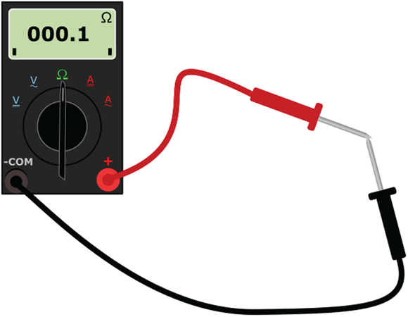
FIGURE 16-6: Touch the test probes of the meter together and verify a zero ohms reading to make sure the meter is working properly.
You can consider the meter calibrated when it reads zero ohms with the test probes shorted together (held together so they’re touching each other). Do this test each time you use your meter, especially if you turn off the meter between tests.
If your meter has a continuity setting, don’t use it to zero-adjust (calibrate) the meter. The tone may sound when the meter reads a few ohms, so it doesn’t give you the accuracy you need. Recalibrate the multimeter using the ohms setting, and not the continuity setting, to ensure proper operation.
Operating Your Multimeter
When you use your multimeter to test and analyze circuits, you must consider what settings to dial up, whether you’re testing components individually or as part of a circuit, whether the circuit should be powered up or not, and where you place the test leads (in series or in parallel with whatever you’re testing).
Think of your multimeter as an electronic component in your circuit (because in a way, it is). If you want to measure voltage, your meter must be placed in parallel with the section of the circuit you’re measuring because voltages across parallel branches of a circuit are the same. If you want to measure current, your meter must be placed in series with the section of the circuit you are measuring because components in a series circuit carry the same current. (You can read about series and parallel connections in Chapter 4.)
In the following sections, I explain how to use your multimeter to measure voltage, current, and resistance in the simple resistor-LED (light-emitting diode) circuit that you see in Figure 16-7.

FIGURE 16-7: A simple resistor-LED circuit.
If you choose to build the resistor-LED circuit and try out your multimeter, here are the parts you need:
- Four 1.5-volt AA batteries
- One four-battery holder (for AA batteries)
- One battery clip
- One 2.2 kΩ 1/4-watt (minimum) resistor (red-red-red)
- One red LED (any size; I use 5 mm)
- One solderless breadboard
- One short jumper wire
Refer to the photo in Figure 16-7 as you build the circuit. Make sure you orient the LED so that its shorter lead is connected to the negative side of your battery pack. You can find the details about constructing circuits using a solderless breadboard in Chapter 15.
The most important thing to remember about solderless breadboards is that they have internal electrical connections. For instance, the five holes in row 10, columns a through e are connected to each other; the five holes in row 10, columns f through j are connected to each other. And all the holes in each individual power rail (those columns labeled + and –) are connected to each other, but the four power rails are not connected to each other.
Measuring voltage
To examine voltage levels — that is, the voltage drop from a point in your circuit to ground — throughout your circuit using a multimeter, your circuit must be powered up. You can test the voltage at almost any point in a circuit. Here’s how to measure voltages:
Select the type of voltage (AC or DC).
In the case of our resistor-LED circuit, select DC volts.
If your multimeter isn’t autoranging, choose the range that gives you the most sensitivity.
If you’re not sure what range to select, start with the broadest range and dial it down later if the measurement falls in a lower range. In the resistor-LED circuit (refer to Figure 16-7), the maximum voltage you can expect to measure is equal to the supply voltage, which is nominally 6 V. Select a range of 10 V or 20 V (meaning 0–10 V or 0–20 V), depending on what your multimeter offers.
Measure a voltage level.
Attach the black lead to the ground connection in the circuit and attach the red lead to the point in the circuit that you want to measure. This action places your multimeter in parallel with the voltage drop from a point in your circuit to ground.
Measure the voltage drop across a circuit component (for instance, a resistor or LED).
Attach the black lead to one side of the component and attach the red lead to the other side of the component. This action places your multimeter in parallel with the voltage drop you want to measure.
If you attach the black lead to the more negative side of the component (that is, the side that is closer to the negative side of the battery pack) and the red lead to the more positive side of the component, your multimeter will register positive volts. If you attach your multimeter leads the other way, your multimeter will register negative volts.
Refer to Figure 16-8 for examples of using a multimeter to measure two different voltage drops in the resistor-LED circuit. In the left image, the meter is measuring the voltage that powers the entire circuit, so the multimeter reads 6.4 V. (Note that the fresh batteries I use are supplying more than their nominal voltages.) In the right image, the meter is measuring the voltage drop across the LED, which is 1.7 V.

FIGURE 16-8: Measuring voltage drops in a resistor-LED circuit.
In some circuits, such as those that handle audio signals, voltages may change so rapidly that your multimeter may not be able to keep up with the voltage swings. To test fast-changing signals, you need a logic probe (for digital signals only) or an oscilloscope.
Measuring current
To measure current, you connect your multimeter in a way that ensures that the same current you want to measure passes through the meter when the circuit is powered up. In other words, you must insert your multimeter in the circuit in series with the component you want to measure current through. This setup, as shown in Figure 16-9, is different from the voltmeter configuration.

FIGURE 16-9: To measure current, connect the meter in series with the circuit or component.
These are the steps you follow to measure current:
Select the type of current (AC or DC).
In the case of our resistor-LED circuit, select DC amps.
If your multimeter isn’t autoranging, choose the range that gives you the most sensitivity.
If you’re not sure what range of current to select, start with the broadest range, and dial it down later if the measurement falls within a lower range. Because the amount of current passing through most electronic circuits can be measured in milliamps (mA), you can start with a range of 200 mA and dial it down to 20 mA if the reading is less than 20 mA. For the resistor-LED circuit (refer to Figure 16-9), select a range of 10 mA or 20 mA, depending on what your multimeter offers.
Interrupt the circuit at the point where you want to measure current.
Attach the black lead of the meter to the more negative side of the circuit and the red lead to the more positive side. This action places your multimeter in series with the component you want to measure current through.
In the resistor-LED circuit (refer to Figure 16-7), current has only one path to flow through, so you can interrupt the circuit between any two components. One way to interrupt the circuit is to remove the jumper that connects the resistor to the LED. Then to measure the current, connect the black multimeter lead to the LED and the red multimeter lead to the resistor, as shown in Figure 16-9.
In a circuit with parallel branches, current splits at each node (the connection between branches). To measure how much current flows through one of the branches, you interrupt the circuit within that branch and insert your meter’s leads to reconnect the circuit. To measure how much overall current an entire circuit draws, you insert your meter’s leads in series with the positive power supply.
Bear in mind that many digital meters are limited to testing currents of 200 mA or less. Be careful: Don’t test higher current if your meter isn’t equipped to do so. And never leave your multimeter in an ammeter position after measuring current. You can damage the meter. Get in the habit of turning off the meter immediately after running a current test.
Measuring resistance
You can run lots of different tests by using your multimeter as an ohmmeter that measures resistance. Obviously, you can test resistors to check their values or see whether they’ve been damaged, but you can also examine capacitors, transistors, diodes, switches, wires, and other components by using your ohmmeter. Before you measure resistance, however, be sure to calibrate your ohmmeter (as described in the earlier section “Setting Up Your Multimeter”).
If your multimeter has specific features for testing capacitors, diodes, or transistors, I recommend that you use those features rather than the methods that I give you in the following sections. But if you have a bare-bones multimeter without those features, these methods can help you.
Testing resistors
Resistors are components that limit current through a circuit. (Refer to Chapter 5 for details.) Sometimes you need to verify that the nominal resistance value marked on the body of a resistor is accurate, or you may want to investigate whether a suspicious-looking resistor with a bulging center and third-degree burns has gone bad.
To test a resistor with a multimeter, follow these steps:
- Turn off the power before you touch your circuit, and then disconnect the resistor you want to test.
Set your multimeter to read ohms.
If you don’t have an autoranging meter, start at a high range and dial down the range as needed.
Position the test leads on either side of the resistor.
It doesn’t matter which test lead is placed on what side of the resistor, because resistors don’t care about polarity.
Take care not to let your fingers touch the metal tips of the test leads or the leads of the resistor. If you touch them, you add the resistance of your body into the reading, producing an inaccurate result.
The resistance reading should fall within the tolerance range of the nominal value marked on the resistor. For instance, if you test a resistor with a nominal value of 1 kΩ and a tolerance of 10%, your test reading should fall in the range of 900 to 1,100 Ω. A bad resistor may be completely open inside (in which case you may get a reading of infinite Ω), may be shorted out (in which case you get a reading of zero Ω), or may have a resistance value outside its stated tolerance range.
Testing potentiometers
As with a resistor, you can test a potentiometer, or pot — which is a variable resistor — using the ohms setting on your multimeter. (For more about pots, refer to Chapter 5.)
Here’s how to do the test:
- Turn off the power before you touch your circuit, and then remove the potentiometer.
Set your multimeter to read ohms.
If you don’t have an autoranging meter, start at a high range and dial down the range as needed.
Position the test leads on two of the potentiometer’s leads.
Depending on where you put the leads, you can expect one of these results:
- With the meter leads applied to one fixed end (point 1) and the wiper, or variable lead (point 2), as shown in Figure 16-10, turning the dial shaft in one direction increases the resistance, and turning the dial shaft in the other direction decreases the resistance.
- With the meter leads applied to the wiper (point 2) and the other fixed end (point 3), the opposite resistance variation happens.
- If you connect the meter leads to both fixed ends (points 1 and 3), the reading that you get should be the maximum resistance of the pot, no matter how you turn the dial shaft.
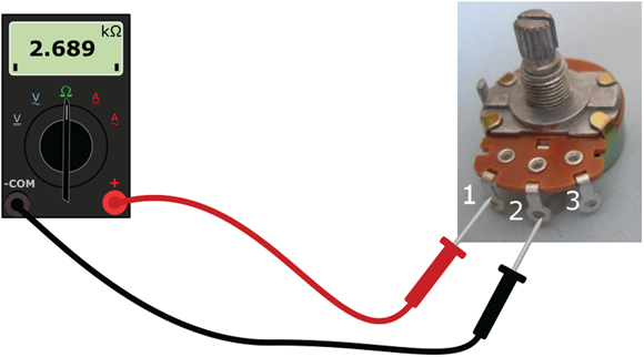
FIGURE 16-10: Connect the test leads to the first and center, center and third, and first and third terminals of the pot.
As you turn the shaft of the potentiometer, take note of any sudden changes in resistance, which may indicate a fault inside the pot. Should you find such a fault, replace the pot with a new one.
Testing capacitors
You use a capacitor to store electrical energy for a short period of time. (For coverage of capacitors, see Chapter 7.) If your multimeter doesn’t have a capacitor-testing feature, you can still use the multimeter in the ohmmeter setting to help you decide whether to replace a capacitor.
Here’s how to test a capacitor:
Before you test a capacitor, be sure you discharge it to clear all the electrical energy out of it.
Large capacitors can retain a charge for long periods of time — even after you remove power.To discharge a capacitor, you short out its terminals through an insulated bleeder jumper (as shown in Figure 16-11), which is simply a wire with a large (1 MΩ or 2 MΩ) resistor attached. The resistor prevents the capacitor from shorting out, which would make it unusable.
- Remove the bleeder jumper.
Dial your multimeter to ohms and touch the test leads to the capacitor leads.
Unpolarized capacitors don’t care which way you connect the leads, but if you’re testing a polarized capacitor, connect the black lead to the negative terminal of the capacitor, and the red lead to the positive terminal. (Chapter 7 explains how to determine capacitor polarity.)
Wait a second or two, and then note the reading.
You’ll get one of these results:
- A good capacitor shows a reading of infinity when you perform this step.
- A zero reading may mean that the capacitor is shorted out.
- A reading of between zero and infinity could be indicative of a leaky capacitor, one that is losing its capability to hold a charge.
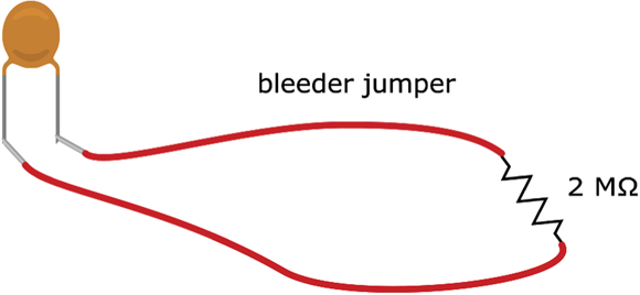
FIGURE 16-11: Purchase or make a bleeder jumper, used for draining excess charge from a capacitor.
This test doesn’t tell you the capacitance value or whether the capacitor is open, which can happen if the component becomes structurally damaged inside or if its dielectric (insulating material) dries out or leaks. An open capacitor reads infinite ohms, just like a good capacitor. For a conclusive test, use a multimeter with a capacitor-testing function.
Testing diodes
A diode is a semiconductor component that acts like a one-way value for current. (To get the details on diodes, see Chapter 9.) If your multimeter doesn’t have a diode-check setting, you can use the ohms setting to test most types of diodes.
To test a diode, follow these steps:
- Set your meter to a low-value resistance range.
Connect the black lead to the diode’s cathode (negative side, with a stripe) and the red lead to its anode (positive side).
The multimeter should display a low resistance.
- Reverse the leads, and you should get an infinite resistance reading.
If you’re not sure which end is up in a diode you’ve got on hand, you can use your multimeter to identify the anode and the cathode. Run resistance tests with leads connected one way, and then with the leads connected the other way. For the lower of the two resistance readings, the red lead is connected to the anode and the black lead is connected to the cathode.
Testing transistors
A bipolar transistor is essentially two diodes in one package, as illustrated in Figure 16-12. (For a PNP transistor, both diodes are reversed.) If your multimeter has neither a transistor-checking feature nor a diode-checking feature, you can use the ohms setting to test most bipolar transistors, in much the same way you test diodes: You set your meter to a low-value resistance range, and test each diode within your transistor in turn.
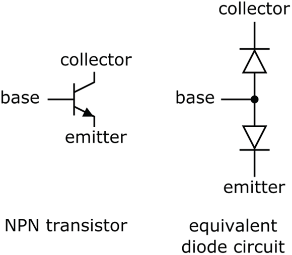
FIGURE 16-12: A bipolar transistor is like two diodes in one package.
Use the following test only with bipolar transistors. Testing with a multimeter can permanently damage some types of transistors, especially field-effect transistors (FETs). If you’re not sure what type of transistor you have, look it up in a datasheet before you test it. You can often find the datasheet by searching the Internet for the component-identification number; for example, you might search for 2N3906 datasheet).
If you’re testing an NPN transistor (such as the one shown in Figure 16-12), follow these steps:
- Set your meter to a low-value resistance range.
Connect the black lead to the collector of the transistor and the red lead to the base.
The multimeter should display a low resistance.
Reverse the leads.
You should get an infinite resistance reading.
Connect the black lead to the emitter and the red lead to the base.
The meter should display a low resistance.
Reverse the leads.
The meter should display infinite resistance.
For a PNP transistor, the readings should be the opposite of what they are for an NPN transistor.
Testing wires and cables
You can use your multimeter as an ohmmeter to run continuity tests on wires and cables. You may want to do this so you can sniff out breaks inside wires and short circuits, or unintended continuity, between two wires in a cable.
To test for continuity in a single wire, connect the multimeter test leads to either end of the wire and dial up a low-range ohms setting. You should get a reading of 0 Ω or a very low number of ohms. A reading of more than just a few ohms indicates a possible break in the wire, causing an open circuit.
To test for a short between different wires that shouldn’t be electrically connected, you set the meter to measure ohms, and then connect one of the test leads to an exposed end of one wire and the other test lead to an exposed end of the other wire. If you get a reading of 0 Ω or a low number of ohms, you may have a short circuit between the wires. A higher reading usually means your wires are not shorted together. (Note that you may get a reading other than infinite ohms if the wires are still connected to your circuit when you make the measurement. Rest assured that your wires are not shorted unless your reading is very low or zero.)
Testing switches
Mechanical switches can get dirty and worn, or sometimes even break, making them unreliable or completely unable to pass electrical current. Chapter 4 describes four common types of switches: single-pole, single-throw (SPST); single-pole, double-throw (SPDT); double-pole, single-throw (DPST); and double-pole, double-throw (DPDT). Depending on the switch, there may be zero, one, or two off positions, and there may be one or two on positions.
You can use your multimeter set to ohms to test any of these switches. Be sure to familiarize yourself with the on/off position(s) and the terminal connections of the particular switch you’re testing — and run tests for each possibility. With your test leads connected across the terminals of any input/output combination placed in the off position, the meter should read infinite ohms; the on position should give you a reading of 0 Ω.
You can most easily test switches by taking them out of a circuit. If the switch is still wired into a circuit, the meter may not show infinite ohms when you place the switch in the off position. If, instead, you get a reading of some value other than 0 Ω, you can assume the switch is operating properly as an open circuit when it’s in the off position.
Testing fuses
Fuses are designed to protect electronic circuitry from damage caused by excessive current flow and, more importantly, to prevent a fire if a circuit overheats. A blown fuse is an open circuit that’s no longer providing protection, so it has to be replaced. Before you test a fuse, make sure you either safely remove it from the circuit or power down the circuit. Then, set your multimeter to the ohms setting and touch one test lead to either end of the fuse. If the meter reads infinite ohms, it means you have a burned-out fuse.
Running other multimeter tests
Many digital multimeters include extra functions that test specific components, such as capacitors, diodes, and transistors. These tests provide more definitive results than the resistance measurements I discuss earlier in this section.
If your multimeter has a capacitor-testing feature, it will display the value of the capacitor. This can come in handy because not all capacitors follow the industry standard identification scheme. Refer to your multimeter manual for the exact procedure because the specifics vary from model to model. Be sure to observe the proper polarity when connecting the capacitor to the test points on the meter.
If your multimeter has a diode-checking feature, you can test a diode by attaching the red test lead to the anode (positive terminal) of the diode, and the black lead to the cathode (negative terminal). You should get a fairly low, but not zero, reading (for instance, 0.5). Then reverse the leads and you should get an overrange reading. If you get two zero readings or two overrange readings, chances are your diode is bad (that is, shorted out or open).
You can use the diode-checking feature to test bipolar junction transistors, treating them as two individual diodes (refer to Figure 16-12).
If your multimeter has a transistor-checking feature, follow the procedure outlined in the manual, which varies from one model to another.
Using a Multimeter to Check Your Circuits
One of the top benefits of a multimeter is that it can help you analyze the rights and wrongs of your circuits. By using the various test settings, you can verify the viability of individual components and confirm that voltages and currents are what they should be. Sooner or later, you hook up a circuit that doesn’t work right away — but your multimeter can help you sniff out the problem if you can’t resolve the problem by physically checking all your connections.
To troubleshoot your circuit, you should first mark up your circuit diagram with component values, estimated voltage levels at various points in the circuit, and expected current levels in each branch of the circuit. (Often the process of marking up the diagram uncovers a math error or two.) Then use your multimeter to probe around.
Here’s a quick list of items to check as you troubleshoot your circuit:
- Power supply voltages
- Individual component functionality and actual values (out of the circuit)
- Continuity of wiring
- Voltage levels at various points in the circuit
- Current levels through part of the circuit (without exceeding the current capabilities of your multimeter)
Using a step-by-step procedure, you can test various components and parts of your circuit and narrow the list of suspects until you either uncover the cause of your circuit problem or admit you need professional help — from your friendly neighborhood electronics guru.