
Chapter 4
Making Connections
IN THIS CHAPTER
![]() Sending current this way and that way
Sending current this way and that way
![]() Examining series and parallel circuits
Examining series and parallel circuits
![]() Controlling connections with switches
Controlling connections with switches
![]() Seeing the light when the power is on
Seeing the light when the power is on
If you've ever been stuck in a traffic jam and decided to take the less crowded side roads, you know that there’s often more than one way to get to a destination. But if your commute requires you to travel, say, over a bridge to cross a major river, you know that sometimes there’s just one way for you — and all the other commuters — to go.
In many ways, electronic circuits are like road systems: They provide paths (roads) for electrons (cars) to travel along, sometimes offering alternate paths and sometimes forcing all the electrons to travel along the same path.
This chapter explores different ways to connect electronic components so you can direct — and redirect — electric current. First, you look at the two basic types of circuit structures — series and parallel — and discover that parallel connections are like alternate traffic routes, whereas series connections are like bridge crossings. Then you find out how switches act like traffic cops — allowing, preventing, or redirecting current flow. Finally, you put it all together by building a circuit that imitates a manually controlled three-stage traffic signal.
Creating Series and Parallel Circuits
Just as you can build structures of all shapes and sizes by connecting LEGOs or K’NEX pieces in various ways, so you can build many different kinds of circuits by connecting electronic components in various ways. Exactly how you connect components dictates how current flows through your circuit — and how voltage is dropped throughout the circuit.
In this section, you explore two kinds of connections. If you would like to build the circuits described in this section, you need the following parts:
- Four 1.5-volt AA batteries
- One four-battery holder (for AA batteries)
- One battery clip
- One 2.2 kΩ resistor (identified by a red-red-red stripe pattern and then a gold or silver stripe)
- Two red LEDs (any size)
- Three insulated alligator clips or one solderless breadboard
 Note that if you’ve already built the basic LED circuit discussed in Chapter 3, you may alter it to build the circuits shown in this section. You need only one additional red LED and, if you choose to use alligator clips to make the connections, one additional alligator clip.
Series connections
In a series circuit, components are arranged along a single path between the positive and negative terminals of a power source. Take a look at Figure 4-1, which shows a series circuit containing a resistor and two LEDs. Current flows from the positive battery terminal through the resistor, through LED1, through LED2, and then back to the negative terminal of the battery. A series circuit has only one path for electrical charges to travel along, so all current passes through each component sequentially.
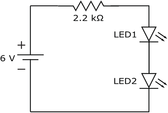
FIGURE 4-1: In a series circuit, current flows through each component sequentially.
 You should remember two important facts about series circuits:
- Each component carries the same current.
- The voltage supplied by the source is divided (though not necessarily evenly) among the components. If you add the voltage drops across each component, you get the total supply voltage.
Using Figure 4-2 as a guide, set up the two-LED series circuit. Use your multimeter set on DC volts to measure the voltage across the battery pack, the resistor, and each of the LEDs. When I did this, I got the following readings:
- Voltage across battery: 6.4 volts
- Voltage across resistor: 3.0 volts
- Voltage across LED1: 1.7 volts
- Voltage across LED2: 1.7 volts
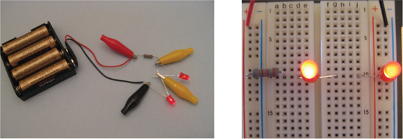
FIGURE 4-2: Two ways to set up the circuit with two LEDs in series.
By summing the voltage drops across the resistor and the LEDs, you get the total voltage supplied by the battery pack:
Next, set your multimeter to the DC current setting. Interrupt the circuit at any of the connection points and insert your multimeter, remembering to keep the positive lead at a higher voltage than the negative lead. When I did this, I got a reading of 1.4 mA. That amount of current flows through each component in this series circuit because there is only one path for current to flow.
Because the current in a series circuit has only one path to flow through, you may run into a potential problem with this type of circuit. If one component fails, it creates an open circuit, stopping the flow of current to every other component in the circuit. So if your expensive new restaurant sign sports 200 LEDs wired in series to say “BEST FOOD IN TOWN,” and a home-run ball knocks out one LED, every one of the LEDs goes dark.
Parallel connections
There’s a way to fix the problem of all components in a series circuit blacking out when one component fails. You can wire the components using parallel connections — such as those in the circuit shown in Figure 4-3. With a parallel circuit, current can flow in multiple paths, so even if several baseballs take out bulbs in your sign, the rest of it stays lit. (Of course, you may be left with a glowing sign reading, “BEST FOO I OWN.” There are pros and cons to everything.)
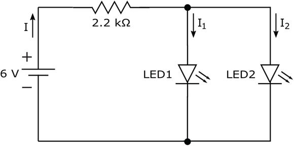
FIGURE 4-3: Light bulbs are often arranged in a parallel circuit so if one burns out, the rest stay lit.
Here’s how the parallel circuit in Figure 4-3 works: Current flows from the positive battery terminal, and then splits at the junction that leads to the parallel branches of the circuit, so each LED gets a share of the supply current. The current flowing through LED1 doesn’t flow through LED2. So if your restaurant sign has 200 LEDs wired in parallel and one burns out, light still shines from the other 199 LEDs.
Two important things you need to remember about parallel circuits are
- The voltage across each parallel branch is the same.
- The current supplied by the source is divided among the branches, and the branch currents sum to the total supply current.
Set up the circuit using the example in Figure 4-4 as your guide. With your multimeter set to DC volts, measure the voltage across the battery pack, the resistor, and each of the LEDs. When I did this, I got the following readings:
- Voltage across battery: 6.4 volts
- Voltage across resistor: 4.7 volts
- Voltage across LED1: 1.7 volts
- Voltage across LED2: 1.7 volts
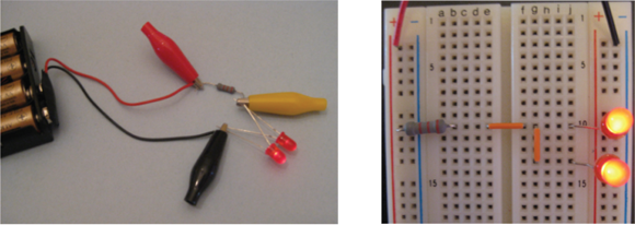
FIGURE 4-4: Two ways to set up the circuit with two LEDs in parallel.
Now, use your multimeter to measure the current flowing through each of the three circuit components, as follows, remembering to set your multimeter to DC current:
- Resistor current (I ): Break the circuit between the resistor and the two LEDs, and insert your multimeter to reconnect the circuit, as shown in Figure 4-5. Because you're placing the multimeter in series with the resistor, you're measuring the current flowing through the resistor. This current is labeled I (refer to Figure 4-3).
- LED1 current (I1): Remove the multimeter and reconnect the resistor to the LEDs. Then disconnect the positive lead of LED1 from the resistor. Insert the multimeter leads into the circuit, as shown in the photo on the left in Figure 4-6. Because the multimeter is in series with LED1, you're measuring the current that flows through LED1. This current is labeled I1 (refer to Figure 4-3).
- LED2 current (I2): Remove the multimeter and reconnect LED1. Then disconnect the positive lead of LED2 from the resistor. Insert the multimeter into the circuit in series with LED2, as shown in the photo on the right in Figure 4-6. (Note that I removed the lower orange jumper to disconnect LED2 from the resistor, and then inserted my multimeter at that opening in the circuit.) You're measuring the current that flows through the LED2, or I2 (refer to Figure 4-3).
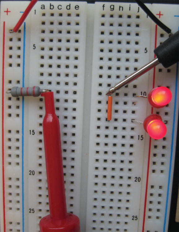
FIGURE 4-5: Measure the current flowing through the resistor.

FIGURE 4-6: Measure the current flowing through LED1 (left) and LED2 (right).
These are the readings I got:
- Resistor current, I: 2.2 mA
- LED1 current, I1: 1.1 mA
- LED2 current, I2: 1.1 mA
If you add the two branch currents, I1 and I2, you find that their total is equal to the current flowing through the resistor, which is the supply current coming from the battery pack:
Note that the supply current for the parallel circuit, 2.2 mA, is higher than the supply current for the series circuit, 1.4 mA, even though the same components are used in both circuits. Connecting circuit components in parallel draws more current from your source than connecting them in series.
If your circuit is powered by a battery, you need to be aware of just how long your battery can supply the necessary current to your circuit. As I discuss in Chapter 12, batteries have ratings of amp-hours. A battery with a rating of one amp-hour (for example) will last for just one hour in a circuit that draws one amp of current — theoretically, anyway. (In practice, even new batteries don’t always deliver on their amp-hour promises.) Therefore, when you’re deciding what power source to use for a circuit, you must take into account both the current that a circuit draws and how long you want to run the circuit.
Switching Electric Current On and Off
Switching is far and away the most important function in electronics. Think about your TV set: You turn it on and off, select a signal source from several different input choices (such as your DVD player, cable box, or gaming system), and change TV channels. Your TV screen consists of millions of tiny pixels (picture elements), each of which is, in essence, a red, blue, or green light that is either on or off. All those TV control and display functions involve switching, whether it’s simply on/off switching or what I like to think of as multiple-choice switching — that is, directing one of several input signals to your TV screen. Likewise, your smartphone, computing device, and even your microwave rely on on/off states (for instance, key pressed or not, or transmit sound now or not) for their control and operation.
So what exactly is switching?
Switching is the making or breaking of one or more electrical connections such that the flow of current is either interrupted or redirected from one path to another. Switching is performed by components called (you guessed it!) switches. When a switch is in the open position, the electrical connection is broken and you have an open circuit with no current flowing. When a switch is in the closed position, an electrical connection is made and current flows.
 Tiny semiconductor transistors (which I discuss in Chapter 10) are at the heart of most of the switching that goes on in electronic systems today. The way in which a transistor works is a bit complicated, but the basic idea behind transistor switching is this: You use a small electric current to control the switching action of a transistor, and that switching action controls the flow of a much larger current.
Aside from transistor switches, lots of different kinds of mechanical and electrically operated switches can be used in electronics projects. These switches are categorized by how they are controlled, the type and number of connections they make, and how much voltage and current they can handle.
Controlling the action of a switch
Switches are referred to by names that indicate how the switching action is controlled. You see some of the many different types of switches in Figure 4-7.
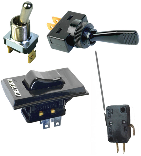
FIGURE 4-7: From top to bottom: two toggle switches, a rocker switch, and a leaf switch.
Chances are, you encounter one or more of the following types of switches as you go about your daily routine:
- Slide switch: You slide a knob back and forth to open and close this type of switch, which you find on many flashlights.
- Toggle switch: You flip a lever one way to close the switch and the other way to open the switch. You may see labels on these switches: on for the closed position, and off for the open position.
- Rocker switch: You press one side of the switch down to open the switch, and the other side of the switch down to close the switch. You find rocker switches on many power strips.
- Leaf switch: You press a lever or button to temporarily close this type of switch, which is commonly used in doorbells.
- Pushbutton switch: You push a button to change the state of the switch, but how it changes depends on the type of pushbutton switch you have:
- Push on/push off buttons: Each press of the button reverses the position of the switch.
- Normally open (NO): This momentary switch is normally open (off), but if you hold down the button, the switch is closed (on). When you release the button, the switch becomes open again. This is also known as a push-to-make switch.
- Normally closed (NC): This momentary switch is normally closed (on), but if you hold down the button, the switch is open (off). When you release the button, the switch becomes closed again. This is also known as a push-to-break switch.
- Relay: A relay is an electrically controlled switch. If you apply a certain voltage to a relay, an electromagnet within pulls the switch lever (known as the armature) closed. You may hear talk of closing or opening the contacts of a relay’s coil. That’s just the term used to describe a relay’s switch.
Making the right contacts
Switches are also categorized by how many connections they make when you “flip the switch” and exactly how those connections are made.
A switch can have one or more poles, or sets of input contacts: A single-pole switch has one input contact, whereas a double-pole switch has two input contacts.
A switch can also have one or more conducting positions, or throws. With a single-throw switch, you either make or break the connection between each input contact and its designated output contact; a double-throw switch allows you to alter the connection of each input contact between each of its two designated output contacts.
Sound confusing? To help clear things up, take a look at the circuit symbols (see Figure 4-8) and descriptions of some common switch varieties:
- Single-pole, single-throw (SPST): This is your basic on/off switch, with one input contact and one output contact, for a total of two terminals that connect to your circuit. You either make the connection (switch on) or break the connection (switch off).
- Single-pole, double-throw (SPDT): This on/on switch contains one input contact and two output contacts (so it has three terminals). It switches the input between two choices of outputs. You use an SPDT switch, or changeover switch, when you want to have a circuit turn one device or another on (for example, a green light to let people know they can enter a room, or a red light to tell them to stay out).
- Double-pole, single-throw (DPST): This dual on/off switch contains four terminals — two input contacts and two output contacts — and behaves like two separate “make-or-break” SPST switches operating in sync. In the off position, both switches are open and no connections are made. In the on position, both switches are closed and connections are made between each input contact and its corresponding output contact.
- Double-pole, double-throw (DPDT): This dual on/on switch contains two input contacts and four output contacts (for a total of six terminals), and behaves like two SPDT (changeover) switches operating in sync. In one position, the two input contacts are connected to one set of output contacts. In the other position, the two input contacts are connected to the other set of output contacts. Some DPDT switches have a third position, which disconnects (or breaks) all contacts. You can use a DPDT switch as a reversing switch for a motor, connecting the motor to positive voltage to turn one way, negative voltage to turn the other way, and, if there is a third switch position, zero voltage to stop turning.
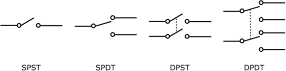
FIGURE 4-8: Circuit symbols for single-pole, single-throw (SPST), single-pole, double-throw (SPDT), double-pole, single-throw (DPST), and double-pole, double-throw (DPDT) switches.
In the next section, titled “Creating a Combination Circuit,” you see how to use an SPDT switch as an on/off (or SPST) switch.
Creating a Combination Circuit
Most circuits are combinations of series and parallel connections. How you arrange components in a circuit depends on what you’re trying to do.
Take a look at the series-parallel circuit in Figure 4-9. Note the three parallel branches, each containing a switch in series with a resistor and an LED. The switches are represented by the symbols at the top of each branch.

FIGURE 4-9: By opening and closing switches in this series-parallel circuit, you can direct the supply current through different paths.
If only one switch is in a closed position, as shown in Figure 4-10 (and in the diagram in Figure 4-9), all the supply current flows through just one LED, which lights, and the other LEDs are off.
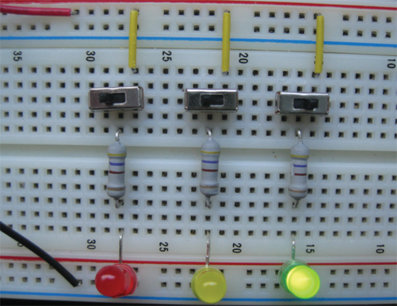
FIGURE 4-10: By turning just the rightmost switch on, only the green LED receives current.
If all three switches are closed, the supply current travels through the resistor and then splits three different ways — with some current passing through each of the three LEDs. If all three switches are open, the current does not have a complete path to follow, so no current flows out of the battery, as shown in Figure 4-11.
By alternating which switch is open at any time, you can control which LED is lit. You can imagine such a circuit controlling the operation of a three-stage traffic light (with additional parts to control the timing and sequencing of the switching action).
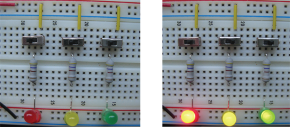
FIGURE 4-11: With all three switches off, none of the LEDs receives current (left). With all three switches on, all three LEDs receive current and light (right).
To analyze combination circuits, you apply voltage and current rules one step at a time, using series rules for components in series and parallel rules for components in parallel. At this point, you don’t quite have enough information to calculate all the currents and voltages in the LED circuits shown here. You need to know about a rule called Ohm’s Law, which I explain in Chapter 6, and about how voltage is dropped across diodes, which I cover in Chapter 9. Then you’ll have everything you need to analyze simple circuits.
To build the three-LED circuit described in this section, you need the following parts:
- Four 1.5-volt AA batteries
- One four-battery holder (for AA batteries)
- One battery clip
- Three 470 Ω resistors (yellow-violet-brown stripes and then a gold or silver stripe)
- Three LEDs (any size, any color; I used one red, one yellow, and one green)
- Three single-pole, double-throw (SPDT) slide switches designed for solderless breadboard use
- One solderless breadboard and assorted jumper wires
Each SPDT switch has three terminals for making connections, but for the three-LED circuit, you need to use only two of the terminals. (See Figure 4-12.) The slider button controls which end terminal gets connected to the center terminal.
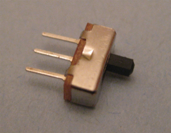
FIGURE 4-12: An SPDT switch can be used as an on/off switch by connecting just two of its three terminals in your circuit.
With the slider in one position, the center terminal is connected to the terminal at the end where the slider is positioned. Move the slider to the other position, and the center terminal is connected to the other end terminal. This type of switch is also known as an on/on switch because it can switch between two circuits, closing one while opening the other.
For the three-LED circuit, you need the switch to function as an on/off switch, so you connect two of the three SPDT terminals in your circuit. Leave the unused end terminal in a breadboard hole but not connected to anything in your circuit, as shown in Figure 4-13. With the slider positioned towards the unused terminal, the switch is off. With the slider positioned towards the other end of the switch, the switch is on.
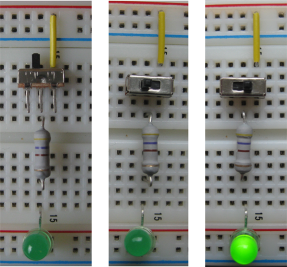
FIGURE 4-13: Using an SPDT switch as an on/off switch.
The simplest type of on/off switch is a two-terminal, single-pole, single-throw (SPST) switch, which simply connects or disconnects the two terminals when you move the slider. But it’s hard to find such a switch with terminals designed to fit into solderless breadboards.
Switching On the Power
You can set up a simple circuit to connect and disconnect your battery pack from any circuits you build on a solderless breadboard without having to physically remove the battery pack from the breadboard.
In Figure 4-14, the positive terminal of the battery is connected to the top terminal of an SPDT switch. The center terminal of the switch is connected to the leftmost column of the breadboard, which is also known as a power rail. By moving the slider on the switch, you make or break a connection between the positive terminal of the battery and the positive power rail. As long as you use the power rails to supply power to your circuits, your switch functions as an on/off switch for powering your breadboard circuits.
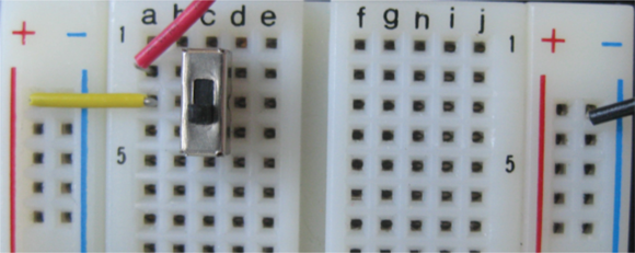
FIGURE 4-14: A switch connects and disconnects a battery from the power rails of a solderless breadboard.
By adding a 470 Ω resistor and an LED between the center terminal of the switch and the negative power rail, you create an indicator light for your on/off switch. (See Figure 4-15.) If the switch is in the off position, the battery is not connected to the LED, so the LED is off. If the switch is in the on position, the battery is connected to the LED, so the LED is on.

FIGURE 4-15: A green LED indicates whether the breadboard is powered up or not.
Note that even without this resistor and LED, the switch still functions as an on/off power switch for your breadboard. But it’s nice to have a visible indicator that the power is on, as shown in Figure 4-16.
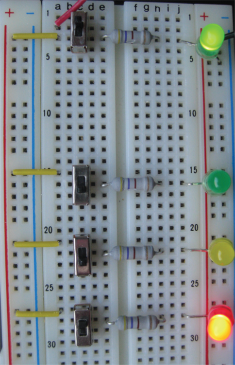
FIGURE 4-16: The green LED in the top right signals that voltage is applied to the power rails and the three-LED circuit is drawing power.
What Do Circuits Look Like?
Circuits usually don’t look as neat and geometric as you might expect. The shape of a circuit is usually not important for its operation. What matters about any circuit — and what you should concern yourself with when building one — is how the components are connected, because the connections show you the path the current takes through the circuit.
The shape of a circuit does matter for circuits involving high-frequency signals, such as radio-frequency (RF) and microwave circuits. The layout, or placement of circuit components, must be designed with care to reduce noise and other undesired AC signals. Additionally, the proximity of bypass capacitors (which you find out about in Chapter 7) to other circuit components can make a difference in the performance of many circuits.
Figure 4-17 is a photograph of a 1980’s style dimmer switch circuit. This simple electronic device uses just a few components to control current flow to a built-in light fixture in my house. But most electronic systems are a lot more complicated than this; they connect lots of individual components in one or more circuits to achieve their ultimate goal.
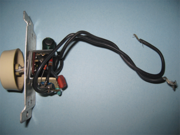
FIGURE 4-17: A dimmer switch is a simple electronic circuit with just a few components.
Figure 4-18 gives you an inside view of the circuitry of a computer hard drive. The circuit consists of the following, all attached to a specialized surface known as a printed circuit board, or PCB:
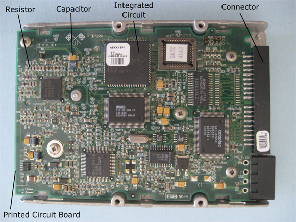
FIGURE 4-18: Computer hard drive electronics.
- Many discrete components (individual parts, such as resistors and capacitors)
- An assortment of integrated circuits, or ICs (which look like electronic centipedes)
- Connectors (which, not surprisingly, connect the hard drive electronics to the rest of the computer).
ICs, which I discuss in Chapter 11, are nothing more than a bunch of tiny circuits that work together to perform a function so commonly desired that it’s worthwhile to mass-produce the circuit and package it in a protective case with leads (the centipede legs) that enable access to the circuit inside.
After you discover how different types of components control current flow in circuits and can apply voltage and current laws, you can begin to design and construct useful electronic circuits.