
Chapter 17
Putting Projects Together
IN THIS CHAPTER
![]() Creating unique light blinkers and flashers
Creating unique light blinkers and flashers
![]() Rigging an alarm
Rigging an alarm
![]() Constructing an adaptable siren
Constructing an adaptable siren
![]() Sounding off with your own amplifier
Sounding off with your own amplifier
![]() Designing a traffic signal
Designing a traffic signal
![]() Making beautiful music
Making beautiful music
Getting up to speed on electronics really pays off when you get to the point where you can actually build a project or two. In this chapter, you get to play with several fun, entertaining, and educational electronics gadgets that you can build in half an hour or less. I selected the projects for their high cool factor and their simplicity. I’ve kept parts to a minimum, and the most expensive project costs under $15 or so to build.
I’ve given you some detailed procedures for the first project, so work through that one first. Then, you should be able to follow the circuit schematics and build the rest of the projects on your own. Check Chapter 11 if you need a refresher on schematics, and browse through Chapter 3 if you’d like to review basic circuit concepts. And if the projects don’t seem to work as advertised (it happens to the best of us), review Chapter 16, arm yourself with a multimeter, and start troubleshooting!
Getting What You Need Right Off the Bat
You can build all the projects in this chapter on a solderless breadboard. Of course, feel free to build any of the projects on a regular soldered circuit board, if you want to keep them around. There’s more detail about breadboarding and building circuits in Chapter 15. If you get stuck on any of these projects, hop to that chapter to help you through.
 You can find all the parts that you need to construct the projects in this chapter at any electronics store or online electronics retailer. If you don't have a well-stocked electronics outlet near you, check out Chapter 19 for some mail-order electronics parts suppliers.
Unless otherwise noted, use these guidelines when selecting components:
- All resistors are rated for 1/4 W or 1/8 W and 5% or 10% tolerance. I include the color code for each resistor value in the parts list for each project.
- All capacitors are rated at a minimum of 25 V. I note the type of capacitor that you need (for instance, disc or electrolytic) in the parts list for each project.
 If you want to understand the ins and outs of one or more of the electronic components you use in these projects, review the material in Chapters 4–7 and 9–12. You’ll find information on switches in Chapter 4, details about resistors and Ohm’s Law in Chapters 5 and 6 respectively, and a treatise on capacitors in Chapter 7. Chapter 9 explains diodes, Chapter 10 discusses transistors, and two of the integrated circuits (ICs) used in these projects are covered in Chapter 11. Wires, power sources, and other parts (for instance, sensors, speakers, and buzzers) are discussed in Chapter 12.
You can learn a lot about a particular IC by looking up its datasheet on the Internet or doing an Internet search for application notes about the part. These information sources tell you much more than just the pinout and power requirements for the ICs; they often provide sample circuits and tips on getting the best performance from the chip. Projects in this chapter use the 555 timer chip, the 4017 decade counter IC, and the LM386 audio amplifier chip.
Creating an LED Flasher Circuit
Your first mission — should you choose to accept it — is to build a circuit containing a single light-emitting diode (LED) that blinks on and off at a rate that you can vary. This may sound simple (and, thanks to the 555 timer IC, it is), but getting the LED to blink means you must successfully build a complete circuit, limit the current in your circuit so that it doesn’t fry your LED, and set up a timer to switch the current on and off so that the light blinks. After you accomplish your mission, you modify the circuit to create a multi-LED flasher that you can mount to the back of your bike to alert motorists to your presence.
If you’ve already built some circuits on a solderless breadboard (say, by following the instructions in previous chapters), you may be somewhat of a pro by now. You may not need the detailed circuit-building instructions that follow in this section, but it’s still a good idea to read along as I explain how to select components for this first circuit.
Exploring a 555 flasher
You can see the schematic of the single LED flasher in Figure 17-1. (If you need a quick refresher course on reading schematics, flip to Chapter 14.) Here are the parts you need to build this circuit:
- 9-volt battery (with battery clip)
- IC1: LM555 timer IC
- R1: 1 MΩ potentiometer
- R2: 47 kΩ resistor (yellow-violet-orange)
- R3: 330 Ω resistor (orange-orange-brown)
- C1: 4.7 μF electrolytic (polarized) capacitor
- C2: 0.01 μF disc (nonpolarized) capacitor
- LED: Light-emitting diode (any size and any color)
Before you build the LED flasher, you might want to do a quick analysis to understand exactly how it works.
The cornerstone of the LED flasher (as well as other projects in this chapter) is the 555 timer IC. You can use this versatile part in a variety of ways, as explained in Chapter 11. For this project, the 555 timer is configured as an astable multivibrator (which is a fancy way of saying it’s an oscillator) generating an ongoing series of on/off pulses at regular intervals, sort of like an electronic metronome. The output of the 555 timer IC, at pin 3, is what you use to switch on and off the LED current.
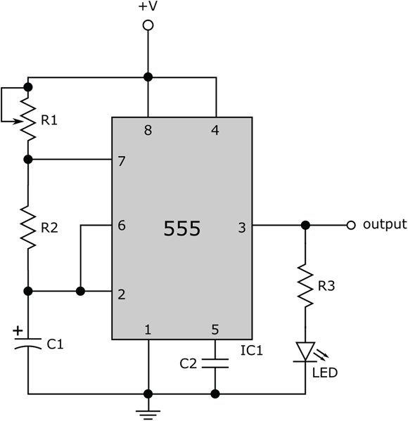
FIGURE 17-1: Schematic of the single LED flasher circuit.
Limiting current through the LED
Resistor R3 is there to keep you from frying your LED. This lowly resistor performs the important job of limiting the current passing through the LED. The output voltage at pin 3 of the 555 timer varies between 9 V (the positive power supply) when the pulse is on and 0 V when the pulse is off.
Assuming the forward voltage drop across the LED is about 2.0 V (a typical value), you know that when the pulse is on, the voltage drop across resistor R3 is about 7 V. You get this result by taking the 9 V at pin 3 and subtracting the 2 V dropped across the LED. From that, you can use Ohm’s Law (see Chapter 6) to calculate the current through R3, which is the same as the current through the LED, as follows:

Now, that’s a current your LED can safely handle!
Controlling the timing of the pulse
Resistors R1 and R2 and capacitor C1 control both the width and the on/off timing interval of the pulse generated by the 555 timer IC (see Chapter 11 for details). This project uses a potentiometer to vary R1 so you can change the rate of the blinking light from slow waltz to fast samba.
The time period, 003A4, is the total time it takes for one up-and-down pulse:
 To figure out the range of time periods that the 555 timer generates, first use 47,000 for R2 (47 kΩ) and 0.0000047 for C1 (4.7 μF) in the equation for T. Then calculate the low end of the timing interval by using 0 for R1 in the equation, and calculate the high end of the timing interval by using 1,000,000 for R1 in the equation. You should expect the timing interval to range from roughly 0.3 seconds to 3.6 seconds as you dial the pot from 0 Ω to 1 MΩ.
Building the LED flasher circuit
To see whether the light blinks at about the rate your calculations say it should, build the LED flasher circuit and try it out! Use Figure 17-2 as your guide. If this is the first circuit you’re building, you may want to follow the detailed instructions in this section.

FIGURE 17-2: An LED flasher with parts mounted on a solderless board. (555 timer IC pin labels have been added.)
You can make it easier to use battery power when you build a circuit on a breadboard using just a switch and a few wires, as shown in Figure 17-2. Use a single-pole, double-throw (SPDT) switch to connect the positive battery terminal to the top positive supply rail (in Chapter 4, I explain this process in detail). Then connect the positive supply rails on top and bottom using a red wire, and the negative supply rails on top and bottom using a black wire, so that power is available on both the top and the bottom of the board.
Here are the steps to build the LED flasher circuit:
Collect all the components you need for the project.
See the parts list in the “Exploring a 555 flasher” section for a rundown of what you need. Nothing is worse than starting a project, only to have to stop halfway through because you don’t have everything at hand!
Carefully insert the 555 timer chip into the middle of the board.
It’s common practice to insert an IC so that it straddles the empty middle row of the breadboard and the clocking notch (that little indentation or dimple on one end of the chip) faces the left of the board.
Insert the two fixed resistors, R2 and R3, into the board, following the schematic and the sample breadboard in Figure 17-2.
Insert the two capacitors, C1 and C2, into the board, following the schematic and the sample breadboard in Figure 17-2.
As noted in Chapter 11, the pins on IC chips are numbered counter-clockwise, starting at the clocking notch. If you’ve placed the 555 timer IC with the clocking notch facing the left side of the board, the pin connections are as shown in Figure 17-2.
- Make sure you orient the polarized capacitor properly, with its negative side connected to ground.
Solder wires to the potentiometer (R1) to connect it into the breadboard.
Use 22-gauge solid-strand hookup wire. The color doesn’t matter. Note that the potentiometer has three connections to it. One connection (at either end) goes to pin 7 of the 555; the other two connections (at the other end and the center) are joined, or bridged, and attached to the positive side of the power supply.
Connect the LED as shown in the schematic and the photo.
Observe proper orientation when inserting the LED: Connect the cathode (negative side, with the shorter lead) of the LED to ground. Check the packaging that came with your LED to make sure you get it right. (If you don’t, and you insert the LED backwards, nothing bad will happen, but the LED won’t light. Simply remove the LED and reinsert it, the other way around.)Use 22-gauge single-strand wire, preferably already precut and trimmed for use with a solderless breadboard, to finish making the connections.
Use the sample breadboard shown in Figure 17-2 as a guide to making these jumper-wire connections.
- Before applying power, double-check your work. Verify all the proper connections by cross-checking your wiring against the schematic.
Finally, attach the 9 V battery to the positive supply and ground rails of the breadboard.
It’s easier if you use a 9 V battery clip, which contains prestripped leads. You may want to solder 22-gauge solid hookup wire to the ends of the leads from the clip; this makes it easier to insert the wires into the solderless breadboard. Remember: The red lead from the battery clip is the positive terminal of the battery, and the black lead is the negative terminal, or ground.
Checking your handiwork
When you apply power to the circuit, the LED should flash. Rotate the R1 knob to change the speed of the flashing. Does the LED blink at the rate you expect it to? If your circuit doesn’t work, disconnect the 9 V battery and check the connections again.
Here are some common mistakes to look for:
- 555 IC inserted backward: This mistake can damage the chip, so if this happens, you might want to try another 555.
- LED inserted backward: Pull it out and reverse the leads.
- Connection wires and component leads not pressed firmly enough into the breadboard sockets: Be sure that each wire fits snugly into the breadboard, so there are no loose connections.
- Wrong component values: Double-check, just in case!
- Dead battery: Try a new one.
- Circuit wired wrong: Have a friend take a look. Fresh eyes can catch mistakes that you might not notice.
You can use your multimeter to test voltages, currents, and resistances in your circuit. As described in Chapter 16, such tests can help you identify the cause of circuit problems. Your multimeter can tell you whether your battery has enough juice, whether your diode is still a diode, and much, much more.
If you’re building a circuit that’s new to you, it’s good electronics practice to build it on a solderless breadboard first. That’s because you often need to tweak a circuit to get it working right. When you have it working to your satisfaction, you can make the circuit permanent if you like. Just take your time — and remember to double- (and even triple-) check your work. Don’t worry — you’ll be an old hand in no time.
Creating an LED Bike Flasher
You can expand the simple LED flasher circuit to create an inexpensive multi-LED flasher that you can use to increase your safety when you go for out for a ride on your bike or a run in the park. Or you can just wear it on your shirt to impress your friends.
Look at the circuit in Figure 17-3. Other than the additional LEDs at the output of the 555 timer IC and the use of a fixed resistor instead of a potentiometer for R1, this circuit seems identical to the simple LED flasher circuit from the previous section. And it is. Well, except for the values of R1, R2, and C1, which are the components that determine the pulse rate that controls the blinking of the LEDs.

FIGURE 17-3: The LED bike flasher circuit. Values of R1, R2, and C1 are selected to create a rapid pulse train that controls the LED flashing action.
For a bike flasher, you want the LEDs to flash at a rapid clip, but not so fast that you can’t distinguish one blink from another. The values shown next for R1, R2, and C1 generate a timing interval of roughly two pulses per second (2 Hz). I also suggest that you use ultrabright LEDs, which are similar to standard LEDs except that they have clear plastic cases so that the light appears to be brighter.
Here is the parts list for the LED bike flasher:
- 9-volt battery (with battery clip)
- IC1: LM555 timer IC
- R1, R2: 1 kΩ resistor (brown-black-red)
- R3: 330 Ω resistor (orange-orange-brown)
- C1: 220 μF electrolytic (polarized) capacitor
- C2: 0.01 μF disc (nonpolarized) capacitor
- LED1-8: Ultrabright light-emitting diode (5 mm, any color)
If you’d like to change the flash rate, try using different values of R1 (or R2 or C1). For instance, using 220 Ω resistors (red-red-brown) for both R1 and R2 produces a flash rate of about 10 pulses per second (10 Hz). And remember to add an on/off switch for the battery if you make this circuit permanent.
Catching Intruders with a Light-Sensing Alarm
Figure 17-4 shows you a schematic of a light-sensing alarm. The idea of this project is simple: If a light comes on, the alarm goes off.
You build the alarm around a 555 timer chip, which acts as a tone generator. The 555 timer is configured (once again) as an oscillator, and the values of R3, R4, and C1 are selected to create an output pulse train (on pin 3) at a frequency in the audible range (20 Hz to 20 kHz).
Note that the reset pin (pin 4) of the 555 timer is not tied to the positive power supply, as it has been in 555 oscillator circuits described previously in this chapter. This fact is significant because if the reset pin is tied high, the 555 timer will just keep on oscillating (and the speaker will keep producing a tone) as long as power is applied. If a low voltage is applied to the reset pin, however, the 555 timer’s internal timing circuit is reset, the output (pin 3) goes low, and the speaker is quiet.

FIGURE 17-4: Schematic of a light alarm.
So, to make the 555 timer sound the alarm only when light is present, you need to create a light-sensitive switch and use it to control the reset pin on the 555 timer. The left side of the circuit in Figure 17-4 provides the light-sensitive switch in the form of a photoresistor-transistor combination.
Transistor Q1 plays the role of the switch, sometimes conducting current and sometimes not conducting current. (You find out what controls Q1 soon.) Transistor Q1 controls the 555 timer reset pin as follows:
When the transistor is not conducting current, the voltage on pin 4 (reset) of the 555 timer goes low.
If the transistor is not conducting current, no current is flowing through resistor R2, so the voltage drop across R2 is 0, and the voltage where the collector of transistor Q1 (that is, the terminal on the lower right side of the transistor in Figure 17-4) meets pin 4 of the 555 timer is 0.
When the transistor is conducting current, the voltage at pin 4 (reset) of the 555 timer goes high.
In Chapter 10, you see that when a transistor is fully conducting, the voltage drop from the collector to the emitter is nearly 0, so in this circuit, the voltage at the collector is nearly equal to the 9 V power supply voltage.
Whether the transistor is on (conducting) or off (nonconducting) depends on what’s happening at the base (left terminal) of the transistor. The base voltage is controlled by a voltage divider (see Chapter 6 for details), which consists of the potentiometer (R1) and the photoresistor. To turn Q1 on, the voltage at its base must go low (see Chapter 11 for details of PNP transistor operation). With little or no light present, the resistance of the photoresistor is very high, so the voltage at the base of transistor Q1 is high and Q1 is off. When light hits the photoresistor, its resistance decreases, the voltage at the base of Q1 goes low, and the transistor is on.
The bottom line is that the light alarm has two possible states:
- Darkness: The resistance of the photoresistor is very high, so the base voltage of transistor Q1 is high, causing Q1 to turn off. With no current flowing through R2, reset pin 4 of the 555 timer is low. As a result, the 555 timer is not oscillating (no alarm).
- Light: The resistance of the photoresistor is low, so the base voltage of transistor Q1 is low, causing Q1 to turn on and conduct current through R2, which then raises the voltage on reset pin 4 of the 555 timer. As a result, the 555 timer oscillates and the alarm sounds.
You can adjust the sensitivity of the alarm by turning the pot (R1), which simply alters the voltage divider ratio, so more (or less) light is needed to turn transistor Q1 on. Decide for yourself whether you want to sense a change from total darkness to low light or from low light to bright light.
Assembling the light alarm parts list
Here’s the shopping list for the light alarm project:
- 9-volt battery (with battery clip)
- IC1: LM555 timer IC
- Q1: 2N3906 PNP transistor
- R1: 100 kΩ potentiometer
- R2: 3.9 kΩ resistor (orange-white-red)
- R3: 10 kΩ resistor (brown-black-orange)
- R4: 47 kΩ resistor (yellow-violet-orange)
- C1, C3: 0.01 μF disc (nonpolarized) capacitor
- C2: 4.7 μF electrolytic or tantalum (polarized) capacitor
- Speaker: 8 Ω, 0.5 W speaker
- Photoresistor: Experiment with different sizes; for example, a larger photoresistor will make the circuit a little more sensitive
Making your alarm work for you
You can apply this light alarm in several practical ways. Here are a few ideas:
- Put the light alarm inside a pantry so it goes off whenever someone raids the chocolate chip cookies. Keep your significant other out of your stash — or keep yourself on that diet! When the pantry door opens, light comes in and the alarm goes off.
- Do you have a complex electronics project in progress in the garage that you don’t want anybody to disturb? Place the alarm inside the garage, near the door. If someone opens the garage door during the day, light comes through and the alarm sounds.
- Build your own electronic rooster that wakes you up at daybreak. (Who needs an alarm clock?)
- Create a room-in-use alert system — but don’t use a noisy speaker. Instead, replace C2 and the speaker with a 330 Ω resistor and an LED. The LED will light up when the photoresistor detects light. Wire the circuit so that most of the parts are in a box in the room and the LED is mounted outside the door to the room.
Playing the C-Major Scale
Figure 17-5 shows a schematic for a primitive electronic keyboard. The circuit may look complicated, but it really is fairly simple if you understand how the 555 timer IC operates as an oscillator.

FIGURE 17-5: The C-major scale circuit, with labels added to show you which switch controls each note and how to tune the scale.
Here are the parts you need to build the C-major scale circuit:
- 9-volt battery (with battery clip)
- IC1: LM555 timer IC
- R1, R7: 2.2 kΩ resistor (red-red-red)
- R2: 10 kΩ resistor (brown-black-orange)
- R3: 10 kΩ potentiometer
- R4: 820 Ω resistor (grey-red-brown)
- R5, R6: 1.8 kΩ resistor (brown-grey-red)
- R8: 1.2 kΩ resistor (brown-red-red)
- R9: 2.7 kΩ resistor (red-violet-red)
- R10: 3 kΩ resistor (orange-black-red)
- C1: 0.1 μF disc (nonpolarized) capacitor
- C2: 0.01 μF disc (nonpolarized) capacitor
- C3: 4.7 μF electrolytic or tantalum (polarized) capacitor
- SW1-8: momentary on, normally open switches (pushbutton)
- Speaker: 8 Ω, 0.5 W speaker
The frequency at which the 555 timer output oscillates depends on the values of two resistances and a capacitor, as you see in Chapter 11 and in other projects in this chapter. Resistor R1 and capacitor C1 are two of the three values that go into the frequency calculation. The other value that helps determine frequency is the resistance found between pins 7 and 2.
There’s no rule that says you have to use a single resistor between pins 7 and 2. The total resistance between the pins helps determine the frequency. In this circuit, you use a series of eight pushbutton switches to select a series of resistors in such a way that the total resistance between pins 7 and 2 helps generate a frequency that corresponds to a specific note. You use a 10 kΩ resistor (R2) as the base resistance, a 10 kΩ potentiometer (R3) to tweak, or tune, all the notes in the scale, and additive resistors (R4–R10) for the total resistance required for each individual note in the C-major scale.
The values of resistors R4–R10 have been carefully calculated to produce the correct tones. For instance, the frequency of the note A on the equal-tempered scale is 440 Hz. The resistance you need between pins 7 and 2 to produce a 440 Hz pulse train is roughly 15.1 kΩ. (You can calculate this resistance yourself by using the formula in Chapter 11 for the frequency of a pulse train produced by the 555 timer used as an astable multivibrator.) By pressing SW3, you are connecting resistors R2, R3, R4, and R5 in series between pins 7 and 2. (Be sure to follow the path of the complete circuit and see for yourself what the total resistance is.) The total resistance (R2+R3+R4+R5) is 12.6 kΩ plus the value of the 10 kΩ pot (that is, R3). If your circuit is tuned properly (by adjusting the pot while using a tuning fork or your accurately tuned piano, if you like), the pot value is roughly 2.5 kΩ. (Keep in mind that resistor values can vary, so your pot value may be a little higher or lower than 2.5 kΩ.)
Set up the circuit and try it out! You can play the C-major scale on it, and maybe even the beginning of a few tunes, such as “Do Re Mi” and “America the Beautiful.” Eventually, you’ll find that you need more notes, such as sharps and flats, or notes beyond one octave. Armed with your knowledge of the 555 timer IC, adding resistors in series, and opening and closing circuits with switches, you can build out this C-major circuit to create more interesting tunes.
Scaring Off the Bad Guys with a Siren
Unless you carry a badge (a real one, not the one in your toy box), you can’t arrest any bad guys when you set off the warbling siren that you build in this project, shown in Figure 17-6. But the siren sounds cool, and you can use it as an alarm to notify you if somebody’s getting at your secret stash of baseball cards, vintage Frank Sinatra records, a signed copy of Mister Spock's Music from Outer Space record, or whatever.
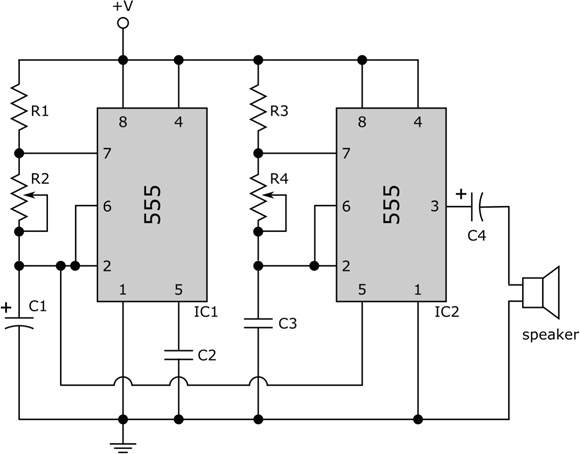
FIGURE 17-6: A police-type siren made from two 555 timer ICs.
Scoping out the 555 siren parts list
To start alarming your friends, gather these parts to build the circuit:
- 9-volt battery (with battery clip)
- IC1, IC2: LM555 timer IC
- R1, R3: 2.2 kΩ resistors (red-red-red)
- R2: 50 kΩ potentiometer
- R4: 100 kΩ potentiometer
- C1: 47 μF electrolytic (polarized) capacitor
- C2: 0.01 μF disc (nonpolarized) capacitor
- C3: 0.1 μF disc (nonpolarized) capacitor
- C4: 4.7 μF electrolytic or tantalum (polarized) capacitor
- Speaker: 8Ω, 0.5 W speaker
How your warbler works
This circuit (refer to Figure 17-6) uses two 555 timer chips. You rig both chips to act as astable multivibrators; that is, they constantly change their output from low to high to low to high — over and over again. The two timers run at different frequencies. The timer chip on the right in Figure 17-6 is configured as a tone generator, producing an audible frequency at its output pin, pin 3. (Humans can hear frequencies in the range of 20 Hz to 20 kHz, give or take a few frequencies.) If the timer chip on the right were acting alone, you would hear a steady, medium-pitch sound from the speaker connected to its output. But instead, the 555 timer chip on the right is acting in concert with the 555 timer chip on the left.
The timer on the left operates at a lower frequency than the timer on the right and is used to modulate (okay, warble) the signal produced by the timer chip on the right. The signal at pin 2 of the 555 chip on the left is a slowly rising and falling ramp voltage, which you connect to pin 5 of the 555 chip on the right.
Normally, you might expect to see the signal at pin 3 of the 555 chip on the left feeding into the 555 chip on the right to trigger the second chip. As discussed in Chapter 11, pin 3 of a 555 chip is where you find the up-and-down output pulse for which 555 timers are famous. For this warbler, you get a more interesting sound by using a different signal — that at pin 2 — to trigger the second 555 chip. The signal at pin 2 of the 555 chip on the left rises and falls slowly as capacitor C1 charges and discharges. (Chapter 7 explains just how a capacitor charges and discharges; this rising and falling capacitor voltage triggers the up-and-down pulse waveform that the 555 timer outputs at pin 3, which you’re not using.) By feeding this capacitor voltage (at pin 2 of the 555 chip on the left) into the control pin (pin 5) of the 555 chip on the right, you override the internal trigger circuitry of the second chip, using a varying trigger signal instead, which helps make your warbler warble.
By adjusting the two potentiometers, R2 and R4, you change the pitch and speed of the siren. You can produce all sorts of siren and other weird sound effects by adjusting these two potentiometers. You can operate this circuit at any voltage between 5 V and about 15 V. To power the gadget, use an easy-to-find 9 V battery (included in the parts list in the preceding section).
Building an Audio Amp with Volume Control
Give your electronics projects a big mouth with a little amplifier designed around parts that are inexpensive and easy to find at most electronics suppliers, such as the LM386 power amplifier IC. This amp boosts the volume from microphones, tone generators, and many other signal sources.
Figure 17-7 shows the schematic for this project, which consists of just 10 parts and a battery. You can operate the amplifier at voltages between 5 V and about 15 V. A 9 V battery does the trick.
Here’s a rundown of the parts you need for this project:
- 9-volt battery (with battery clip)
- IC1: LM386 power amplifier
- R1: 10 kΩ potentiometer (optional)
- R2: 10 Ω resistor (brown-black-orange)
- C1: 10 μF electrolytic (polarized) capacitor (optional)
- C2: 0.1 μF disc (nonpolarized) capacitor
- C3, C6: 10 μF electrolytic (polarized) capacitor
- C4: 220 μF electrolytic (polarized) capacitor
- C5: 0.047 μF disc (nonpolarized) capacitor
- Speaker: 8 Ω, 0.5 W speaker

FIGURE 17-7: Schematic of the audio amplifier.
Just connect a signal source (for instance, a RadioShack condenser microphone, part 270-092, which requires a DC power source) across the inputs, making sure to connect the ground of the signal source to the common ground of the amplifier circuit. The LM386 does most of the work for you in this little circuit. Here’s what the other parts in this circuit do:
- C1 is an optional decoupling capacitor that prevents DC from passing from an earlier stage (for instance, if you use a tone generator or other device as the input signal source). The parts list says to use a 10 μF capacitor for C1, but you may try values as low as 0.1 μF (or try eliminating C1 and observe what happens).
- R1 is an optional potentiometer that you can use to control the volume. (You connect the wiper to pin 3 of the LM386, with one end terminal to C1 and the other end terminal to common ground. If you don’t want volume control, leave out R1 and connect the negative side of C1 to pin 3 of the LM386.)
- C2 and C6 are bypass capacitors that isolate the LM386 internal circuitry from any power supply noise, hum, or spikes.
- Capacitor C3 boosts the gain of the LM386 from 20 (without C3) to about 200. (Note that this information is straight off the datasheet for the LM386.)
- Capacitor C4 filters out the DC component of the LM386 output so that only the audio signal reaches the speaker.
- The resistor-capacitor pair, R2-C5, prevents high-frequency oscillations.
This simple circuit puts out a whole lotta sound in a small and portable package. And the better the microphone and speaker, the better the sound!
Try connecting your portable music player to the input of this audio amp. Get an old set of earbuds and do the following: Cut off one of the earbuds, strip the insulation off the wires, and identify the signal and ground wires. Then connect signal and ground across the amplifier inputs, insert the earbud plug into your music player’s jack, and enjoy the sound!
If you want to witness the effects of noise on a sensitive circuit, remove capacitors C2 and C6 (but do not replace them with wires or anything else) and try out the amplifier. You will probably hear lots of crackling.
Creating Light Chasers
If you were a fan of the Knight Rider television series that aired in the ’80s, you remember the sequential light chaser that the KITT Car sported in front. In this section, I show you two versions of the light chaser, each of which uses just two inexpensive ICs and a handful of other parts. You may want to choose one circuit or the other to build. Light Chaser 1 is a little easier to understand. Light Chaser 2 adds a layer of complexity to increase the cool factor.
The parts lists for the two circuits are nearly the same. The main parts list, which includes labels that reference the schematics shown in Figures 17-8 and 17-9, for both circuits is as follows:
- 9-volt battery (with battery clip)
- IC1: LM555 timer IC
- IC2: 4017 CMOS decade counter IC
- R1: 1 MΩ potentiometer
- R2: 47 kΩ resistor (yellow-violet-orange)
- R3: 330 Ω resistor (orange-orange-brown)
- C1: 0.1 μF disc (nonpolarized) capacitor
- C2: 0.01 μF disc (nonpolarized) capacitor

FIGURE 17-8: Schematic for Light Chaser 1.
In addition to the main parts list, Light Chaser 1 uses these parts:
- LED1–LED10: LED (any size and any color)
In addition to the main parts list, Light Chaser 2 uses these parts:
- LED1–LED6: LED (any size and any color)
- D1–D8: 1N4148 diode
Building Light Chaser 1
The schematic for Light Chaser 1 is shown in Figure 17-8. For this design, each of 10 LEDs will light up in succession (that is, following the pattern 1-2-3-4-5-6-7-8-9-10), and the pattern will repeat itself continuously as long as the circuit has power.
 The 4017 decade counter and other CMOS chips are very sensitive to static electricity, and you can easily fry the part if you aren't careful. Make sure you take special precautions, such as wearing an antistatic wrist strap (as described in Chapter 13), before handling the 4017 CMOS IC.
Controlling the lights
The circuit for Light Chaser 1 in Figure 17-8 has two sections:
- The brains: A 555 timer IC makes up the first section, on the left of the schematic. You wire this chip to function as an astable multivibrator (see Chapter 11 for details). The 555 produces a series of pulses on its output pin (pin 3); you determine the speed of the pulses by dialing potentiometer R1.
- The body: The second section, on the right of the schematic, contains a 4017 CMOS decade counter chip with LEDs connected to each of its 10 output pins. As I explain in Chapter 11, pins 1–7 and pins 9–11 on the 4017 chip go from low to high one at a time (but not in the same order as the pin numbers) when a trigger signal is connected to pin 14. Resistor R3 limits the current passing through whichever LED is activated at any given time.
- The connection: The LEDs are switched when the 4017 receives a pulse (on pin 14) from the 555 output (pin 3). You wire the 4017 so it repeats the 1-to-10 sequence, over and over again, for as long as the circuit has power. By adjusting the pot (R1), you can change the speed of the lighting sequence.
Arranging the LEDs
You can build Light Chaser 1 on a solderless breadboard to try it out. If you plan to make it into a permanent circuit, give some thought to the arrangement of the ten LEDs. For example, to achieve different lighting effects, you can try the following:
- Put all the LEDs in a row, in sequence: The lights chase each other up (or down) over and over again.
- Put all the LEDs in a row, but alternate the sequence left and right: Wire the LEDs so the sequence starts from the outside and works its way inward.
- Place the LEDs in a circle so the LEDs sequence clockwise or counterclockwise: This light pattern looks like a roulette wheel.
- Arrange the LEDs in a heart shape: You can use this arrangement to make a unique Valentine's Day present.
Building Light Chaser 2
Figure 17-9 shows another way to build a light chaser. The left side of Light Chaser 2 is the same as the left side of Light Chaser 1, so the brains of both circuits operate in the same way. The right side of Light Chaser 2 is set up so that the LEDs light up sequentially from LED1 through LED6 and then back down to LED1. The lighting sequence follows this repeating pattern: 1-2-3-4-5-6-5-4-3-2. By adjusting the pot (R1), you can change the speed of this bidirectional lighting sequence.
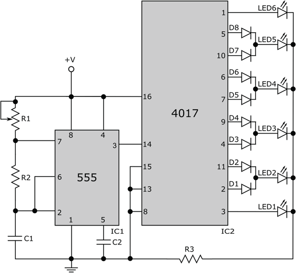
FIGURE 17-9: Schematic for Light Chaser 2.
Note that each of the middle LEDs (LED2–LED5) is connected to two output pins on the 4017 decade counter IC, with a diode between each output pin and the LED. By connecting two output pins to one LED, you enable that LED to light up twice during each count from 0 to 9. You need to include a diode at each output pin to prevent current from flowing back into the 4017 chip. (Chapter 9 explains that diodes operate like one-way valves for current.) For instance, when 4017 pin 5 goes high, current flows from pin 5 through D8 and LED5 (lighting it up), but diode D7 prevents any of that current from flowing back into the 4017 chip through pin 10.
Red Light, Green Light, 1-2-3!
In this section, I show you how to use a 555 timer chip and the 4017 decade counter (once again) to build a simulated green-yellow-red traffic signal. The schematic for the traffic signal is shown in Figure 17-10. Here are the parts you need to build this circuit:
- 9-volt battery (with battery clip)
- IC1: LM555 timer IC
- IC2: 4017 CMOS decade counter IC
- R1: 100 kΩ potentiometer
- R2: 22 kΩ resistor (red-red-orange)
- R3: 330 Ω resistor orange-orange-brown)
- C1: 100 μF electrolytic (polarized) capacitor
- C2: 0.01 μF disc (nonpolarized) capacitor
- LED1: green LED (any size)
- LED2: yellow LED (any size)
- LED3: red LED (any size)
- D1–D10: 1N4148 diode
Diode D5 is not necessary in the circuit shown in Figure 17-10 However, you need diode D5 for some of the tweaks to the design of this circuit I describe later, so you might as well include D5 from the get-go.
The 555 timer chip is used in astable mode to generate a low-frequency square-wave pulse on output pin 3. Note that the value of capacitor C1 is 100 μF — much larger than the C1 value used to control the light chaser circuits in the previous section. The larger the capacitance, the longer it takes to charge the capacitor, and the longer it takes to trigger the 555 chip via pin 2. So the 555 timer output (pin 3) oscillates at a much slower rate than in the light chaser circuits.
By varying the resistance of the potentiometer (R1), you control the timing cycle, but because this pot is smaller than the pot used in the light chaser circuits, you can’t vary the timing quite as much. The full duration of the timing cycle (that is, the time it takes to complete one up-and-down pulse on pin 3 of the 555 timer IC) is designed to range from about 3 seconds to about 10 seconds.

FIGURE 17-10: Schematic for a three-light traffic signal.
Each timing pulse from the 555 chip triggers the decade counter to count, so the 10 outputs of the decade counter go high one at a time every 3 to 10 seconds (depending on the value of R1). Because the first four outputs of the 4017 chip (pins 3, 2, 4, and 7, in that order) are connected (through diodes) to the green LED (LED1), the green LED will light up and remain lit during the first four pulses from the 555 timer chip. The fifth output of the 4017 chip (pin 10) is connected to the yellow LED (LED2), so it will light up for the duration of the fifth timing pulse. Because the sixth through tenth outputs (pins 1, 5, 6, 9, and 11, in that order) of the 4017 chip are tied (through diodes) to the red LED (LED3), the red LED will light up and stay lit for the sixth through tenth timing pulses. Then, the cycle will repeat. (See Figure 17-11.)
Here are some ways in which you can tweak your traffic light design:
- Change the duration of the yellow and red lights: Disconnect the cathode (negative side) of diode D6 from LED3, and then connect it (that is, the cathode of diode D6) to LED2. Now the yellow LED will stay lit for two (instead of one) pulses, and the red LED will stay lit for four (instead of five) pulses.

FIGURE 17-11: The pulse train from the 555 timer chip triggers the 4017 decade counter to activate the green, yellow, and red LEDs according to a designed timing sequence.
- Add another yellow state: In the UK, traffic lights transition from green to yellow to red to yellow to green. To create this sequence, disconnect the cathode of diode D10 from LED3, and then connect that cathode to LED2. Now the last pulse in the 10-pulse train will activate the yellow LED, creating the timing sequence used in the UK.
- Change the speed of the overall timing sequence: Replace C1 with a 47 μF capacitor. The entire timing sequence should be roughly half of what it used to be. Or try using different values for R2 or a different potentiometer for R1. (Refer to Chapter 11 for timing equations.)
- Create a blinking red light (these are popular in New Jersey): Remove the yellow and green LEDs (LED1 and LED2) so that you're essentially disconnecting 4017 output pins 2, 3, 4, 7, and 10. Replace C1 with a 4.7 μF capacitor. Your red light blinker should cycle on and off every 0.5 to 5 seconds (depending on the value of the pot, R1). (Of course, this is overkill. You don’t need the 4017 decade counter to do this; you just need a 555 timer IC and some resistors and capacitors.)
- Replace the pot (R1) with a fixed resistor: If you’re happy with a specific timing sequence and want to build a permanent circuit, there’s no need to use a bulky potentiometer.
Maybe you may know some kids who would love to have a traffic signal to use while they’re playing with toy cars and trucks, riding their Big Wheels in your driveway, or playing “Red Light, Green Light, 1-2-3!” with a bunch of friends. You can test the circuit on a solderless breadboard, tweak the design to suit the needs of your young customers, and then build a permanent circuit and enclose it in a shiny box that has three holes for the LEDs and a hook or stand for mounting. (If you do create such a project, remember to include an on/off switch for your battery.)