
Chapter 7
Getting Charged Up about Capacitors
IN THIS CHAPTER
![]() Storing electrical energy in capacitors
Storing electrical energy in capacitors
![]() Charging and discharging capacitors
Charging and discharging capacitors
![]() Saying “no” to DC and “yes” to AC
Saying “no” to DC and “yes” to AC
![]() Creating the dynamic duo: capacitors and resistors
Creating the dynamic duo: capacitors and resistors
![]() Blocking, filtering, smoothing, and delaying signals
Blocking, filtering, smoothing, and delaying signals
If resistors are the most popular electronic component, capacitors are a close second. Skilled at storing electrical energy, capacitors are important contributors to all sorts of electronic circuits — and your life would be a lot duller without them.
Capacitors make it possible to change the shape (the pattern over time) of electrical signals carried by current — a task resistors alone cannot perform. Although they’re not as straightforward to understand as resistors, capacitors are essential ingredients in many of the electronic and industrial systems you enjoy today, such as radio receivers, computer memory devices, and automobile airbag-deployment systems, so it’s well worth investing your time and brain power in understanding how capacitors operate.
This chapter looks at what capacitors are made of, how they store electrical energy, and how circuits use that energy. You get to watch a capacitor charge, store energy, and later release its energy. Then you find out how capacitors work closely with resistors to perform useful functions. Finally, I showcase the various uses of capacitors in electronic circuits — proving beyond a shadow of a doubt that capacitors are worth getting charged up about.
Capacitors: Reservoirs for Electrical Energy
When you’re thirsty for water, you can generally get a drink in two ways: by catching water that originated from a source and flows out of pipes when you turn on the tap, or by getting water from a storage container, such as a water cooler. You can think about electrical energy in a similar vein: You can get electrical energy directly from a source (such as a battery or a generator), or you can get it from a device that stores electrical energy — a capacitor.
Just as you fill a water cooler by connecting it to a water source, you fill a capacitor with electrical energy by connecting it to a source of electrical energy. And just as water stored in a water cooler remains even after the source is removed, so too the electrical energy stored in a capacitor remains even after the source is removed. In each case, the stuff (water or electrical energy) stored in the device stays there until something comes along and taps into it — whether it’s a thirsty consumer or an electronic component in need of electrical energy.
A capacitor is a two-terminal electronic device that stores electrical energy transferred from a voltage source. (See Figure 7-1.) If you remove the voltage source and electrically isolate the capacitor (so that it isn't connected in a complete circuit), it holds onto the stored electrical energy. If you connect it to other components in a complete circuit, it will release some or all of the stored energy. A capacitor is made from two metal plates separated by an insulator, which is known as a dielectric.
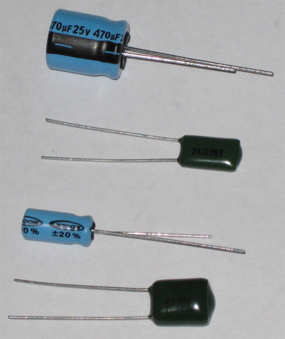
FIGURE 7-1: Capacitors come in a variety of shapes and sizes.
Charging and Discharging Capacitors
If you supply a DC voltage to a circuit containing a capacitor in series with a light bulb (as shown in Figure 7-2), current flow cannot be sustained because there’s no complete conductive path across the plates. In other words, capacitors block DC current. However, electrons do move around this little circuit — temporarily — in an interesting way.

FIGURE 7-2: When a battery is placed in a circuit with a capacitor, the capacitor charges. A charged capacitor stores electrical energy, much like a battery.
Remember that the negative terminal of a battery has a surplus of electrons. So in the circuit shown in Figure 7-2, the surplus electrons begin to move away from the battery toward one side of the capacitor. After they reach the capacitor, they’re stopped in their tracks, with no conductive path to follow across the capacitor. The result is an excess of electrons on that plate.
At the same time, the positive terminal of the battery attracts electrons from the other capacitor plate, so they begin to move. As they pass through the light bulb, they light it (but only for a split second, which I explain in the next paragraph). A net positive charge (due to a deficiency of electrons) is produced on that plate. With a net negative charge on one plate, and a net positive charge on the other plate, the result is a voltage difference across the two plates. This voltage difference represents the electrical energy stored in the capacitor.
The battery keeps pushing electrons onto one plate (and pulling electrons off the other plate) until the voltage drop across the capacitor plates is equal to the battery voltage. At this equilibrium point, there is no voltage differential between the battery and the capacitor, so there’s no push for electrons to flow from the battery to the capacitor. The capacitor stops charging, and electrons stop moving through the circuit — and the light bulb goes out.
When the voltage drop across the plates is equal to the battery voltage, the capacitor is said to be fully charged. (It’s really the capacitor plates that are charged; the capacitor as a whole has no net charge.) Even if the battery remains connected, the capacitor will no longer charge because there is no voltage differential between the battery and the capacitor. If you remove the battery from the circuit, current will not flow and the charge will remain on the capacitor plates. The capacitor looks like a voltage source, as it holds the charge, storing electrical energy.
 The larger the battery voltage you apply to a capacitor, the larger the charge that builds up on each plate, and the larger the voltage drop across the capacitor — up to a point. Capacitors have physical limitations: They can handle only so much voltage before the dielectric between the plates is overcome by the amount of electrical energy in the cap and begins to give up electrons, resulting in current arcing across the plates. You can read more about this in “Keeping an eye on the working voltage,” later in this chapter.
If you replace the battery with a simple wire, you provide a path through the bulb for the surplus electrons on one plate to follow to the other (electron-deficient) plate. The capacitor plates discharge through the light bulb, lighting it up again briefly — even without a battery in the circuit — until the charge on both plates is neutralized. The electrical energy that had been stored in the capacitor is consumed by the light bulb. When the capacitor is discharged (again, it’s really the plates that discharge), no more current will flow.
A capacitor can store electrical energy for hours on end. You’d be wise to make sure a capacitor is discharged before handling it, lest it discharges through you. To discharge a capacitor, carefully place a small incandescent bulb across its terminals, using insulated alligator clips (refer to Chapter 2) to make the connection. If the bulb lights up, you know the capacitor was charged, and the light should dim and go out in a few seconds as the capacitor discharges. If you don’t have a bulb handy, place a 1 MΩ 1 W resistor across the terminals and wait at least 30 seconds. (Refer to Chapter 16 for details.)
Watching a capacitor charge
The circuit shown in Figure 7-3 enables you to observe a capacitor charging and discharging right before your very eyes. The capacitor is symbolized by a straight line facing a curved line.

FIGURE 7-3: This circuit enables you to watch a capacitor charging and discharging.
You need these parts to build the circuit:
- One 9-volt battery with battery clip
- One 470 μF electrolytic capacitor
- One 2.2 kΩ 1/4 W resistor (red-red-red)
- Two light-emitting diodes (LEDs), any size, any colors you have on hand
- One single-pole, double-throw (SPDT) switch
- Two or three jumper wires
- One solderless breadboard
Chapter 2 tells you where to find the necessary parts. I walk you through the circuit setup in this section, but if you want to know more before you begin, refer to Chapter 9 for the lowdown on LEDs and Chapter 15 for detailed information about constructing circuits using a solderless breadboard.
Using Figure 7-4 as your guide, set up the circuit by following these steps:
Insert the SPDT switch vertically across any three rows in an inner column of the left-of-center section of your breadboard.
In one position (labeled charge in Figure 7-3), this changeover switch will connect the 9 V battery to the circuit, allowing the capacitor to charge up. In the other position (labeled discharge in Figure 7-3), the switch will disconnect the battery and replace it with a wire, so that the capacitor can discharge.
- Insert a small jumper wire between the positive power rail and the lower end terminal of the SPDT switch.
Insert a jumper wire between the upper end terminal of the switch and the negative power rail.
I used two small jumper wires and internal breadboard connections to connect the switch to the negative power rail (refer to Figure 7-4), but you can use one longer wire to connect the switch terminal directly to the negative power rail.
Position the switch slider towards the upper end terminal.
This discharge position is shown in Figure 7-4.
Insert the 2.2 kΩ resistor into the breadboard.
Connect one side (either one will do) of the resistor to a hole in the same row as the center terminal of the SPDT switch. Connect the other side of the resistor to a hole in an open row (for neatness, make this connection in the same column as the connection for the first side of the resistor).
Insert the 470 μF electrolytic capacitor into the breadboard.
 A 470 μF electrolytic capacitor is polarized, so it matters which way you insert the capacitor. The capacitor should have a minus sign (–) or arrow indicating the negative terminal. If it doesn’t, check the length of the leads; the shorter lead is on the negative side.
Connect the positive side to the side of the resistor not connected to the switch by inserting the cap lead into a hole in the same row as the resistor lead. Connect the negative side of the cap to a hole in the right-of-center section of the breadboard. Be sure to check the orientation of the capacitor because if you insert it the wrong way, you may damage — or even blow up — the capacitor.
Insert the LEDs in the breadboard in parallel with each other but flipped in orientation.
LEDs are polarized, so it matters which way you orient them. Current flows from the positive side to the negative side but not vice versa (refer to Chapter 9 for details). The negative side of an LED has a shorter lead.Insert the positive side of LED1 in the same row as the negative side of the capacitor. Connect the negative side of LED1 to the negative power rail. Insert the negative side of LED2 into the same row as the negative cap lead and the positive side of LED2 into the negative power rail.
Connect the 9-volt battery.
Connect the negative battery terminal to the negative power rail. Connect the positive battery terminal to the positive power rail.

FIGURE 7-4: Setting up the capacitor charging/discharging circuit.
After you have the circuit set up, you are ready to observe the capacitor charging and discharging.
Keeping an eye on the LEDs, move the slider on the switch to the charge position (towards the lower end terminal). Did LED1 light? Did it stay lit? (It should light immediately, and then grow dimmer until it goes out, in roughly 5 seconds.)
Then, move the slider on the switch back to the discharge position (towards the upper end terminal). Did LED2 light, then grow dimmer and go out after about 5 seconds?
With the switch in the charge position, the battery is connected to the circuit and current flows as the capacitor charges. LED1 lights temporarily, as current flows through it, for as long as it takes the capacitor to charge. After the capacitor stops charging, current no longer flows and LED1 goes out. Note that LED2 is oriented “backwards” so current does not pass through it as the capacitor charges.
With the switch in the discharge position, the battery is replaced by a wire (or, rather, two jumper wires and an internal connection in the breadboard, which together are the equivalent of a single wire connection). The capacitor discharges and current flows through the resistor and LED2, which lights as long as the capacitor is discharging. After the capacitor stops discharging, current stops flowing and LED2 goes out.
You can flip the switch back and forth as much as you like to observe the LEDs lighting and dimming as the capacitor charges and discharges.
The resistor protects the LEDs by limiting the current that flows through them (refer to Chapter 5 for details). The resistor also slows down the capacitor’s charging/discharging process so that you can observe the LEDs lighting. By carefully selecting the resistor and capacitor values, you can control the charge/discharge timing, as you see in the section titled “Teaming Up with Resistors,” later in this chapter.
Opposing voltage change
Because it takes time for charges to build on the capacitor plates when a DC voltage is applied, and it takes time for the charge to leave the plates after the DC voltage is removed, capacitors are said to “oppose voltage change.” This just means that if you suddenly change the voltage applied to a capacitor, it can’t react right away; the voltage across the capacitor changes more slowly than the voltage you applied.
Think about being in your car, stopped at a red light. When the light turns green, you get your car moving again, building speed until you reach the speed limit. It takes time to get to that speed, just like it takes time for a capacitor to get to a certain voltage level. If you switch on a battery across a resistor, however, the voltage across the resistor changes almost instantaneously.
It takes some time for the capacitor voltage to “catch up” to the source voltage. That isn't a bad thing; many circuits use capacitors because it takes time to charge them. This is the crux of the reason why capacitors can change the shape (pattern) of electrical signals.
Giving alternating current a pass
Although capacitors cannot pass direct current (DC) — except temporarily, as you saw in the preceding section — because of the dielectric providing a barrier to electron flow, they can pass alternating current (AC).
Suppose you apply an AC voltage source across a capacitor. Remember that an AC voltage source varies up and down, rising from 0 volts to its peak voltage, then falling back through 0 volts and down to its negative peak voltage, then rising back through 0 volts to its peak voltage, and so on. Imagine being an atom on one of the capacitor plates and looking at the AC source terminal nearest you. Sometimes you feel a force pulling your electrons in one direction, and other times you feel a force pulling your electrons in the other direction. In each case, the strength of the force will vary over time as the source voltage varies in intensity. You and the other atoms on the capacitor plate will alternate between giving up electrons and receiving electrons as the source voltage swings up and down.
What’s really happening is that as the AC source voltage rises from 0 volts to its peak voltage, the capacitor charges, just as it does when you apply a DC voltage. When the supply voltage is at its peak, the capacitor may or may not be fully charged (it depends on a bunch of factors, such as the size of the capacitor plates). Then the source voltage starts to decrease from its peak down to 0 volts. As it does, at some point, the source voltage becomes lower than the capacitor voltage. When this happens, the capacitor starts to discharge through the AC source. Then the source voltage reverses polarity and the capacitor discharges all the way. As the source voltage keeps heading down toward its negative peak voltage, charges start to build up in reverse on the capacitor plates: The plate that previously held more negative charges now holds positive charges, and the plate that previously held more positive charges now holds more negative charges. As the source voltage rises from its negative peak, the capacitor again discharges through the AC source, but in the direction opposite to that of its original discharge, and the cycle repeats. This continuous charge/discharge cycle can occur thousands — even millions — of times per second, as the capacitor tries to keep up, so to speak, with the ups and downs of the AC source.
 Because the AC source is constantly changing direction, the capacitor goes through a continuous cycle of charging, discharging, and recharging. As a result, electrical charges move back and forth through the circuit, and even though virtually no current flows across the dielectric (except a small leakage current), the effect is the same as if current were flowing through the capacitor. These amazing capacitors are said to pass alternating current (AC) even though they block direct current (DC).
If you add a light bulb to your capacitor circuit powered by an AC voltage source, the bulb will light and will stay lit as long as the AC source is connected. Current alternates its direction through the bulb, but the bulb doesn’t care which way current flows through it. (Not so for an LED, which cares very much which way current flows.) Although no current ever passes through the capacitor, the charging/discharging action of the capacitor creates the effect of current flowing back and forth through the circuit.
Discovering Uses for Capacitors
Capacitors are put to good use in most electronic circuits you encounter every day. The key capabilities of capacitors — storing electrical energy, blocking DC current, and varying opposition to current depending on applied frequency — are commonly exploited by circuit designers to set the stage for extremely useful functionality in electronic circuits.
Here are some of the ways capacitors are used in circuits:
Storing electrical energy: Many devices use capacitors to store energy temporarily for later use. Uninterruptible power supplies (UPSs) and alarm clocks keep charged capacitors on hand in case there's a power failure. The energy stored in the capacitor is released the moment the charging circuit is disconnected (which it will be if the power goes out!).
Cameras use capacitors for temporary storage of the energy used to generate the flash, and many electronic devices use capacitors to supply energy while the batteries are being changed. Car audio systems commonly use capacitors to supply energy when the amplifier needs more than the car’s electrical system can give. Without a capacitor in your system, every time you hear a heavy bass note, your lights would dim!
Preventing DC current from passing between circuit stages: When connected in series with a signal source (such as a microphone), capacitors block DC current but pass AC current. This is known as capacitive coupling or AC coupling, and when used this way, the capacitor is known as a coupling capacitor.
Multistage audio systems commonly use this functionality between stages so that only the AC portion of the audio signal — the part that carries the encoded sound information — from one stage is passed to the next stage. Any DC current used to power components in a previous stage is removed before the audio signal is amplified.
- Smoothing out voltage: Power supplies that convert AC to DC, such as your cellphone charger, often take advantage of the fact that capacitors don’t react quickly to sudden changes in voltage. These devices use large electrolytic capacitors to smooth out varying DC supplies. These smoothing capacitors keep the output voltage at a relatively constant level by discharging through the load when the DC supply falls below a certain level. This is a classic example of using a capacitor to store electrical energy until you need it: When the DC supply can’t maintain the voltage, the capacitor gives up some of its stored energy to take up the slack.
- Creating timers: Because it takes time to charge and discharge a capacitor, capacitors are often used in timing circuits to create ticks and tocks when the voltage rises above or falls below a certain level. The timing of the ticking and tocking can be controlled through the selection of the capacitor and other circuit components. (For details, see the section “Teaming Up with Resistors,” later in the chapter.)
Tuning in (or out) frequencies: Capacitors are often used to help select or reject certain electrical signals — which are time-varying electric currents that carry encoded information — depending on their frequency.
For instance, a tuning circuit in a radio-receiver system relies on capacitors and other components to allow the signal from just one radio station at a time to pass through to the amplifier stage, while blocking signals from all other radio stations. Each radio station is assigned a specific broadcast frequency, and it's the radio builder’s job to design circuits that tune in target frequencies. Because capacitors behave differently for different signal frequencies, they are a key component of these tuning circuits. The net effect is a kind of electronic filtering.
Characterizing Capacitors
Capacitors can be built in lots of ways by using different materials for the plates and dielectric and by varying the size of the plates. The particular makeup of a capacitor determines its characteristics and influences its behavior in a circuit.
Defining capacitance
Capacitance is the capability of a body to store an electric charge. The same term — capacitance — is used to describe just how much charge a capacitor can store on either one of its plates. The higher the capacitance, the more charge the capacitor can store at any one time.
The capacitance of any given capacitor depends on three things: the surface area of the metal plates, the thickness of the dielectric between the plates, and the type of dielectric used (more about dielectrics later in this section).
You don’t need to know how to calculate capacitance (and, yes, there is a scary-looking formula), because any capacitor worth its salt will come with a documented capacitance value. It just helps to understand that how much charge a capacitor’s plates can hold depends on how the capacitor is made.
Capacitance is measured in units called farads. One farad (abbreviated F) is defined as the capacitance needed to get one amp of current to flow when the voltage changes at a rate of one volt per second. Don’t worry about the details of the definition; just know that one farad is a humongous amount of capacitance. You’re more likely to run across capacitors with much smaller capacitance values — hovering in the microfarad (μF) or picofarad (pF) range. A microfarad is a millionth of a farad, or 0.000001 farad, and a picofarad is a millionth of a millionth of a farad, or 0.000000000001 farad.
Here are some examples:
- A 10 μF capacitor is 10 millionths of a farad.
- A 1 μF capacitor is 1 millionth of a farad.
- A 100 pF capacitor is 100 millionths of a millionth of a farad, or you could say it is 100 millionths of a microfarad. Whew!
Larger capacitors (1 F or more) are used for system energy storage, and smaller capacitors are used in a variety of applications, as shown in Table 7-1.
TABLE 7-1 Capacitor Characteristics
Type |
Typical Range |
Application |
Ceramic |
1 pF to 2.2 μF |
Filtering, bypass |
Mica |
1 pF to 1 μF |
Timing, oscillator, precision circuits |
Metalized foil |
0.01 to 100 μF |
DC blocking, power supply, filtering |
Polyester (Mylar) |
0.001 to 100 μF |
Coupling, bypass |
Polypropylene |
100 pF to 50 μF |
Switching power supply |
Polystyrene |
10 pF to 10 μF |
Timing, tuning circuits |
Tantalum (electrolytic) |
0.001 to 1,000 μF |
Bypass, coupling, DC blocking |
Aluminum electrolytic |
10 to 220,000 μF |
Filtering, coupling, bypass, smoothing |
Most capacitors are inexact beasts. The actual capacitance of the capacitor can vary quite a bit from the nominal capacitance. Manufacturing variations cause this problem; capacitor makers aren’t just out to confuse you. Fortunately, the inexactness is seldom an issue in home-brewed circuits. Still, you need to know about these variations so that if a circuit calls for a higher-precision capacitor, you know what to buy. As with resistors, capacitors are rated by their tolerance, which is expressed as a percentage.
Keeping an eye on the working voltage
The working voltage, sometimes abbreviated as WV, is the highest voltage that the manufacturer recommends placing across a capacitor safely. If you exceed the working voltage, you may damage the dielectric, which could result in current arcing between the plates, like a lightning strike during a storm. You could short out your capacitor and allow all sorts of unwanted current to flow — and maybe even damage nearby components.
Capacitors designed for DC circuits are typically rated for a WV of no more than 16 V to 35 V. That’s plenty for DC circuits that are powered by sources ranging from 3.3 V to 12 V. If you build circuits that use higher voltages, be sure to select a capacitor that has a WV of at least 10% to 15% more than the supply voltage in your circuit, just to be on the safe side.
Choosing the right dielectric for the job
Designers of electronic circuitry specify capacitors for a project by the dielectric material in them. Some materials are better in certain applications and are inappropriate for other applications. For instance, electrolytic capacitors can handle large currents but perform reliably only for signal frequencies of less than 100 kHz, so they are commonly used in audio amplifiers and power supply circuits. Mica capacitors, however, exhibit exceptional frequency characteristics and are often used in radio frequency (RF) transmitter circuits.
The most common dielectric materials are aluminum electrolytic, tantalum electrolytic, ceramic, mica, polypropylene, polyester (or Mylar), and polystyrene. If a circuit diagram calls for a capacitor of a certain type, be sure you get one that matches.
Refer to Table 7-1 for a list of the most common capacitor types, their typical value range, and common applications.
Sizing up capacitor packaging
Capacitors come in a variety of shapes and sizes (refer to Figure 7-1). Aluminum electrolytic and paper capacitors commonly come in a cylindrical shape. Tantalum electrolytic, ceramic, mica, and polystyrene capacitors have a more bulbous shape because they typically get dipped into an epoxy or plastic bath to form their outside skin. However, not all capacitors of any particular type (such as mica or Mylar) get manufactured the same way, so you can't always tell the component by its cover.
Your parts supplier may label capacitors according to the way their leads are arranged: axially or radially. Axial leads extend from each end of a cylindrically shaped capacitor, along its axis; radial leads extend from one end of a capacitor and are parallel to each other (until you bend them for use in a circuit).
If you go searching for capacitors inside your tablet or laptop, you may not recognize some of them. That’s because many of the capacitors in your PC don’t have any leads! Surface-mount packages for capacitors are extremely small and are designed to be soldered directly to printed circuit boards (PCBs). Since the 1980s, high-volume manufacturing processes have been using surface-mount technology (SMT) to connect capacitors and other components directly to the surface of PCBs, saving space and improving circuit performance.
Being positive about capacitor polarity
Some larger-value electrolytic capacitors (1 μF and up) are polarized — meaning that the positive terminal must be kept at a higher voltage than the negative terminal, so it matters which way you insert the capacitor into your circuit. Polarized capacitors are designed for use in DC circuits.
Many polarized capacitors sport a minus (–) sign or a large arrow pointing toward the negative terminal. For radial capacitors, the negative lead is often shorter than the positive lead.
If a capacitor is polarized, you really, really need to make sure to install it in the circuit with the proper orientation. If you reverse the leads, say, by connecting the + side to the ground rail in your circuit, you may cause the dielectric inside the capacitor to break down, which could effectively short-circuit the capacitor. Reversing the leads may damage other components in your circuit (by sending too much current their way), and your capacitor may even explode.
Reading into capacitor values
Some capacitors have their values printed directly on them, either in farads or portions of a farad. You usually find this to be the case with larger capacitors because there is enough real estate for printing the capacitance and working voltage.
Most smaller capacitors (such as 0.1 μF or 0.01 μF mica disc capacitors) use a three-digit marking system to indicate capacitance. Most folks find the numbering system easy to use. But there’s a catch! (There’s always a catch.) The system is based on picofarads, not microfarads. A number using this marking system, such as 103, means 10, followed by three zeros, as in 10,000, for a total of 10,000 picofarads. Some capacitors are printed with a two-digit number, which is simply its value in picofarads. For instance, a value of 22 means 22 picofarads. No third digit means no zeros to tag on to the end.
For values over 1,000 picofarads, your parts supplier will most likely list the capacitor in microfarads, even if the markings on it indicate picofarads. To convert the picofarad value on the capacitor into microfarads, just move the decimal point six places to the left. So a capacitor marked with a 103 (say, the example in the preceding paragraph) has a value of 10,000 pF or 0.01 μF.
Suppose you’re building a circuit that calls for a 0.1 μF disc capacitor. You can convert microfarads into picofarads to figure out what marking to look for on the capacitor package. Just move the decimal point six places to the right, and you get 100,000 pF. Because the three-digit marking consists of the first two digits of your pF value (10) followed by the additional number of zeros (4), you’ll need a mica disc capacitor labeled 104.
You can use Table 7-2 as a reference guide to common capacitor markings that use this numbering system.
Another, less-often-used numbering system uses both numbers and letters, like this: 4R1. The placement of the letter R tells you the position of the decimal point: 4R1 is really 4.1. This numbering system doesn't indicate the units of measure, however, which can be either microfarads or picofarads.
You can test capacitance with a capacitor meter or a multimeter with a capacitance input (refer to Chapter 16 for details). Most meters require that you plug the capacitor directly into the test instrument because the capacitance can increase with longer leads, making the reading less accurate.
TABLE 7-2 Capacitor Value Reference
Marking |
Value |
nn (a number from 01 to 99) |
nn pF |
101 |
100 pF |
102 |
0.001 μF |
103 |
0.01 μF |
104 |
0.1 μF |
221 |
220 pF |
222 |
0.0022 μF |
223 |
0.022 μF |
224 |
0.22 μF |
331 |
330 pF |
332 |
0.0033 μF |
333 |
0.033 μF |
334 |
0.33 μF |
471 |
470 pF |
472 |
0.0047 μF |
473 |
0.047 μF |
474 |
0.47 μF |
On many capacitors, a single-letter code indicates the tolerance. You may find that letter placed by itself on the body of the capacitor or placed after the three-digit mark, like this: 103Z.
Here the letter Z denotes a tolerance of +80% to –20%. This tolerance means that the capacitor, rated at 0.01 μF, may have an actual value that’s as much as 80% higher or 20% lower than the stated value. Table 7-3 lists the meanings of common code letters used to indicate capacitor tolerance. Note that the letters B, C, and D represent tolerances expressed in absolute capacitance values, rather than percentages. These three letters are used on only very small (pF range) capacitors.
TABLE 7-3 Capacitor Tolerance Markings
Code |
Tolerance |
B |
±0.1 pF |
C |
±0.25 pF |
D |
±0.5 pF |
F |
±1% |
G |
±2% |
J |
±5% |
K |
±10% |
M |
±20% |
P |
+100%, –0% |
Z |
+80%, –20% |
Varying capacitance
Variable capacitors allow you to adjust capacitance to suit your circuit’s needs. The most common type of variable capacitor is the air dielectric, which is found frequently in the tuning controls of AM radios. Smaller-variable capacitors are often used in radio receivers and transmitters, and they work in circuits that use quartz crystals to provide an accurate reference signal. The value of such variable capacitors typically falls in the 5 pF to 500 pF range.
Mechanically controlled variable capacitors work by changing the distance between the capacitor plates or by changing the amount of overlap between the surfaces of the two plates. A specially designed diode (a semiconductor device, discussed in Chapter 9) can function as an electronically controlled variable capacitor; such devices are known as varactors or varicaps — and you can change their capacitance by changing the DC voltage you apply to them.
Chances are, you interact with variable capacitors more than you would with a spouse. Variable capacitors are behind many touch-sensitive devices, such as certain smartphone screens, computer keyboard keys, control panels on many appliances and in some elevators, and the buttons on your favorite remote control. One type of microphone uses a variable capacitor to convert sound into electrical signals, with the diaphragm of the mic acting as a movable capacitor plate. Sound fluctuations make the diaphragm vibrate, which varies the capacitance, producing voltage fluctuations. This device is known as a condenser microphone, so-named because capacitors used to be called condensers.
Interpreting capacitor symbols
Figure 7-5 shows the circuit symbols for different types of capacitors. There are two commonly used capacitor circuit symbols: one with two parallel lines (representing the capacitor plates) and the other with one line and one curve. The curved side represents the more negative side of a polarized capacitor; however, some folks use the two types of symbols interchangeably. Usually, if a circuit has a polarized capacitor, you'll see a plus sign (+) on one side of the capacitor symbol, showing you how to orient the capacitor in the circuit. An arrow through either type of symbol represents a variable capacitor.

FIGURE 7-5: Circuit symbols for capacitors.
Combining Capacitors
You can combine capacitors in series, parallel, or a combination of both to get whatever value of capacitance you need. But as you’ll see, the rules for combining capacitors are different from the rules for combining resistors.
Capacitors in parallel
Figure 7-6 shows two capacitors in parallel, with the common connection points labeled A and B. Note that point A is connected to one plate of capacitor C1 and one plate of capacitor C2. Electrically speaking, point A is connected to a metal plate that is the size of the two plates combined. Likewise for point B, which is connected to both the other plate of capacitor C1 and the other plate of capacitor C2. The larger the surface area of a capacitor plate, the larger the capacitance.

FIGURE 7-6: Capacitors in parallel add up.
Capacitors in parallel add up: Each metal plate of one capacitor is tied electrically to one metal plate of the parallel capacitor. Each pair of plates behaves as a single larger plate with a higher capacitance (refer to Figure 7-6).
The equivalent capacitance of a set of capacitors in parallel is
C1, C2, C3, and so forth represent the values of the capacitors, and Cparallel represents the total equivalent capacitance.
For the capacitors in Figure 7-6, the total capacitance is
If you place the capacitors in Figure 7-6 in a working circuit, the voltage across each capacitor would be the same, and current flowing in to point A would split up to travel through each capacitor and then join together again at point B.
Capacitors in series
Capacitors placed in series work against each other, reducing the effective capacitance in the same way that resistors in parallel reduce the overall resistance. The calculation looks like this:
C1 and C2 are the values of the individual capacitors, and Cseries is the equivalent capacitance. The total capacitance (in μF) of a 100 μF capacitor in series with a 220 μF capacitor, as shown in Figure 7-7, is
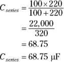
You can temporarily ignore the μ part of μF while you’re performing the calculation just shown — as long as all the capacitance values are in μF and you remember that the resulting total capacitance is also in μF.
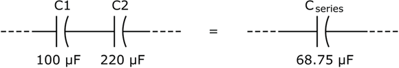
FIGURE 7-7: Capacitors in series work against each other, reducing overall capacitance.
The equivalent capacitance of a set of capacitors in series is
As for any components in series, the current running through each capacitor in series is the same, but the voltage dropped across each capacitor may be different.
Teaming Up with Resistors
Capacitors are often found working hand in hand with resistors in electronic circuits, combining their talent for storing electrical energy with a resistor’s control of electron flow. Put these two capabilities together and you can control how fast electrons fill (or charge) a capacitor — and how fast those electrons empty out (or discharge) from a capacitor. This dynamic duo is so popular that circuits containing both resistors and capacitors are known by a handy nickname: RC circuits.
Timing is everything
Take a look at the RC circuit in Figure 7-8. The battery will charge the capacitor through the resistor when the switch is closed.
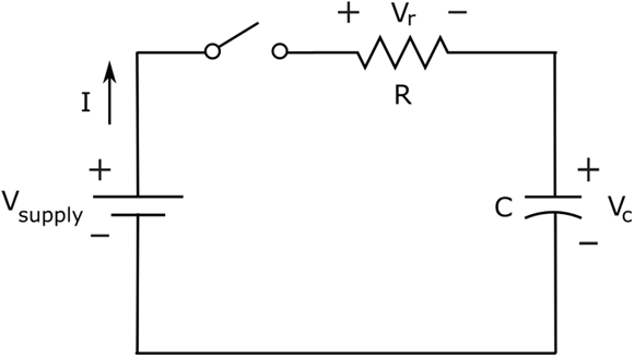
FIGURE 7-8: The capacitor charges until its voltage equals the supply voltage.
Assuming the capacitor was discharged to begin with, the initial voltage across the capacitor, Vc, is zero. When you close the switch, current starts to flow and charges start to build up on the capacitor plates. Ohm’s Law (refer to Chapter 6) tells you that the charging current, I, is determined by the voltage across the resistor, Vr, and the value of the resistor, R, as follows:
And because the voltage drops equal the voltage rises around the circuit, you know that the resistor voltage is the difference between the supply voltage, Vsupply, and the capacitor voltage, Vc:
Using those two facts, you can analyze what is going on in this circuit over time, as follows:
- Initially: Because the capacitor voltage is initially zero, the resistor voltage is initially equal to the supply voltage.
- Charging: As the capacitor begins to charge, it develops a voltage, so the resistor voltage begins to fall, which in turn reduces the charging current. The capacitor continues to charge, but at a slower rate because the charging current has decreased. As Vc continues to increase, Vr continues to decrease, so the current continues to decrease.
- Fully charged: When the capacitor is fully charged, current stops flowing, the voltage drop across the resistor is zero, and the voltage drop across the capacitor is equal to the supply voltage.
If you remove the battery and replace it with a wire so that the circuit consists of just the resistor and the capacitor, the capacitor will discharge through the resistor. This time, the voltage across the resistor is equal to the voltage across the capacitor (![]() ), so the current is Vc/R. Here’s what happens:
), so the current is Vc/R. Here’s what happens:
- Initially: Because the capacitor is fully charged, its voltage is initially Vsupply. Because
 , the resistor voltage is initially Vsupply, so the current jumps up immediately to Vsupply /R. This means the capacitor is shuffling charges from one plate to the other pretty quickly.
 - Discharging: As charges begin to flow from one capacitor plate to the other, the capacitor voltage (and so Vr) starts to drop, resulting in a lower current. The capacitor continues to discharge, but at a slower rate. As Vc (and so Vr) continues to decrease, so does the current.
- Fully discharged: When the capacitor is fully discharged, current stops flowing, and no voltage is dropped across either the resistor or the capacitor.
The waveform in Figure 7-9 shows how, when a constant voltage is applied and then removed from the circuit, the capacitor voltage changes over time as the capacitor charges and discharges through the resistor.

FIGURE 7-9: The voltage across a capacitor changes over time as the capacitor charges and discharges.
How fast the capacitor charges (and discharges) depends on the resistance and capacitance of the RC circuit. The larger the resistance, the smaller the current that flows for the same supply voltage — and the longer it takes the capacitor to charge. A smaller resistance allows more current to flow, charging the capacitor faster.
Likewise, the larger the capacitance, the more charges it takes to fill the capacitor plates, so the longer it takes to charge the capacitor. During the discharge cycle, a larger resistor slows down the electrons more as they move from one plate to the other, increasing the discharge time, and a larger capacitor holds more charge, taking longer to discharge.
Calculating RC time constants
By choosing the values of the capacitor and the resistor carefully, you can adjust a capacitor’s charge and discharge time. As it turns out, your choice of resistance, R, and capacitance, C, defines the time it takes to charge and discharge your chosen capacitor through your chosen resistor. If you multiply R (in ohms) by C (in farads), you get what is known as the RC time constant of your RC circuit, symbolized by T. And that makes another handy formula:
A capacitor charges and discharges almost completely after five times its RC time constant, or 5RC (which means 5×R×C). After time has passed that’s equivalent to one time constant, a discharged capacitor will charge to roughly two-thirds its capacity — and a charged capacitor will discharge nearly two-thirds of the way.
For instance, suppose you choose a 2 MΩ resistor and a 15 μF capacitor for the circuit in Figure 7-7. You calculate the RC time constant as follows:

Now you know that it will take about 150 seconds (or 2½ minutes) to fully charge or discharge the capacitor. If you’d like a shorter charge/discharge cycle time, you can reduce the value you choose for the resistor or the capacitor (or both). Suppose that you have only a 15 μF capacitor, and you want to charge it in five seconds. You can figure out what resistor you need to make this happen as follows:
- Find the RC time constant: You know that it takes five times the RC time constant to fully charge the capacitor, and you want to fully charge your capacitor in five seconds. That means that
 seconds, so
  second.
 - Calculate R: If
 second, and C is 15 μF, then you know that
  , which is approximately 66,667 Ω or 67 kΩ.
Varying the RC time constant
To see that you really can control the time it takes to charge and discharge a capacitor, you can build the circuit shown in Figure 7-10 and use your multimeter to observe the voltage changes across the capacitor. You can also observe the capacitor holding its charge (that is, storing electrical energy).
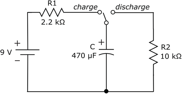
FIGURE 7-10: By choosing different resistance values, you can alter the charge time and discharge time of a capacitor.
The circuit in Figure 7-10 is really two circuits in one. The changeover switch alternates between positions labeled charge and discharge, creating two circuit options:
- Charging circuit: When the switch is in the charge position, the circuit consists of the battery, resistor R1, and the capacitor, C. Resistor R2 is not connected to the circuit.
- Discharging circuit: When the switch is in the discharge position, the capacitor is connected to resistor R2 in a complete circuit. The battery and resistor R1 are disconnected from the circuit (they are open).
To build this circuit, you need the following parts:
- One 9-volt battery with battery clip
- One 470 μF electrolytic capacitor
- One 2.2 kΩ resistor (red-red-red)
- One 10 kΩ resistor (brown-black-orange)
- One jumper wire (which will play the role of the changeover switch)
- One solderless breadboard
Set up the circuit using Figure 7-11 as your guide. Make sure that you place one end of the jumper wire into your breadboard so that it’s electrically connected to the positive side of the capacitor. Then you can use the other end to connect the capacitor to R1 (to complete the charging circuit) or to R2 (to complete the discharging circuit). You can also leave the other end of the jumper wire unconnected (as it is in Figure 7-11), which I suggest you do later in this section. You’ll see why soon.
To watch the capacitor charge, hold its charge, and then discharge, follow these steps:
Set your multimeter to DC volts with a range of 10 V and connect it across the capacitor.
Connect the red multimeter lead to the positive side of the cap and the black multimeter lead to the negative side of the cap (see Figure 7-11).

FIGURE 7-11: Circuit setup for observing different RC time constants for charging and discharging a capacitor.
Charge the capacitor.
Connect the changeover switch to the charge position by placing the free end of the jumper wire into a hole in the same row as the unconnected side of R1. Observe the voltage reading on your meter. You should see the meter reading rise to approximately 9 V as the capacitor charges through resistor R1. It should take about 5 seconds for the capacitor to charge completely.
Put the capacitor in a holding pattern.
Remove the end of the jumper wire that you connected in Step 2 and just let it hang. Observe the voltage reading on your meter. Your meter should continue to read 9 V or thereabouts. (You may see the reading decrease a tiny bit, as the capacitor discharges slowly through the internal resistance of your meter.) The capacitor is holding its charge (really, storing electrical energy), even without the battery connected.
Let the capacitor discharge.
Connect the changeover switch to the discharge position by placing the free end of the jumper wire into a hole in the same row as the unconnected side of R2. Observe the voltage reading on your meter. You should see the reading decrease, as the capacitor discharges through resistor R2 to 0 V. It should take roughly 25 seconds for the capacitor to fully discharge.
In the preceding section (“Calculating RC time constants”), you find out that a capacitor in a simple RC circuit reaches nearly its full charge at approximately five times the RC time constant, T. T is simply the value of the resistance (in ohms) times the value of the capacitance (in farads). So you can calculate the time it takes to charge and discharge the capacitor in your circuit as follows:
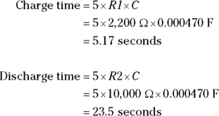
Do those charge/discharge times seem close to what you observed? Repeat the charging and discharging experiment using a timer, and see if your calculations seem about right.
If you want to explore further, try replacing R1 and R2 with different resistances or use a different capacitor. Then calculate the charge/discharge times you expect to see and measure the actual times as you charge and discharge the capacitor. You’ll find that the RC time constant doesn’t disappoint!