
Chapter 8
Identifying with Inductors
IN THIS CHAPTER
![]() Inducing currents in coils with a changing magnetic field
Inducing currents in coils with a changing magnetic field
![]() Opposing changes in current with an inductor
Opposing changes in current with an inductor
![]() Using inductors in filter circuits
Using inductors in filter circuits
![]() Resonating with RLC circuits
Resonating with RLC circuits
![]() Making frequencies crystal-clear
Making frequencies crystal-clear
![]() Coupling magnetic flux to transfer energy between circuits
Coupling magnetic flux to transfer energy between circuits
Many of the best inventions in the world, including penicillin, sticky notes, champagne, and the pacemaker, were the result of pure accidental discovery. One such serendipitous discovery — the interaction between electricity and magnetism — led to the development of two amazingly useful electronic components: the induction coil and the transformer.
The induction coil, or inductor, stores electrical energy in a magnetic field and shapes electrical signals in a different way than does a capacitor. Whether operating alone, in special pairs known as transformers, or as part of a team along with capacitors and resistors, inductors are at the heart of many modern-day conveniences you might not want to live without, including radio systems, television, and the electric power transmission network.
This chapter exposes the relationship between electricity and magnetism and explains how 19th-century scientists purposely exploited that relationship to create inductors and transformers. You get a look at what happens when you try to change the direction of current through an inductor too quickly. Then you explore how inductors are used in circuits and why crystals ring at just one frequency. Finally, you get a handle on how transformers transfer electrical energy from one circuit to another — without any direct contact between the circuits.
Kissing Cousins: Magnetism and Electricity
Magnetism and electricity were once thought to be two separate phenomena, until a 19th-century scientist named Hans Christian Ørsted discovered that a compass needle moved away from magnetic north when current supplied by a nearby battery was switched on and off. Ørsted’s keen observation led to lots of research and experimentation, ultimately confirming the fact that electricity and magnetism are closely related. After several years (and many more accidental discoveries), Michael Faraday and other 19th-century scientists figured out how to capitalize on the phenomenon known as electromagnetism to create the world’s first electromechanical devices. Today’s power transformers, electromagnetic generators, and many industrial motors are based on the principles of electromagnetism.
This section looks at how electricity and magnetism interact.
Drawing the (flux) lines with magnets
Just as electricity involves a force (voltage) between two electrical charges, magnetism involves a force between two magnetic poles. If you’ve ever performed the classic grade-school science experiment in which you place a magnet on a surface and toss a bunch of iron filings near the magnet, you’ve seen the effects of magnetic force. Remember what happened to the filings? They settled into curved linear paths from the north pole of the magnet to its south pole. Those filings showed you the magnetic lines of force — also known as flux lines — within the magnetic field created by the magnet. You may have seen more filings closer to the magnet because that’s where the magnetic field is strongest. Figure 8-1 shows the pattern produced by invisible lines of flux around a magnet.
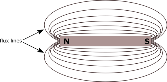
FIGURE 8-1: Magnetic lines of force exist in parallel flux lines from a magnet’s north pole to its south pole.
Magnetic flux is just a way to represent the strength and direction of a magnetic field. To understand magnetic lines of flux, think about the effects of air on a sailboat’s sail. The stronger the wind and the larger the sail, the greater the force of air on the sail. But if the sail is oriented parallel to the direction of wind flow, air slips by the sail and even a strong wind will not move the sail. The effect of the wind is greatest when it hits the sail head-on — that is, when the surface of the sail is perpendicular to the direction of wind flow. If you try to represent the strength and direction of the wind and the orientation of the sail in a diagram, you might draw arrows showing the force of the wind extending through the surface of the sail. Likewise, lines of magnetic flux illustrate the strength and orientation of a magnetic field, showing you how the force of the magnetic field will act on an object placed within the field. Objects placed in the magnetic field will be maximally affected by the force of the magnetic field if they are oriented perpendicular to the flux lines.
Producing a magnetic field with electricity
 As Ørsted discovered, electrical current running through a wire produces a weak magnetic field surrounding the wire. This is why the compass needle moved when the compass was close to Ørsted’s circuit. Stop the current from flowing, and the magnetic field disappears. This temporary magnet is electronically controllable — that is, you can turn the magnet on and off by switching current on and off — and it’s known as an electromagnet.
With the current on, the lines of force encircle the wire and are spaced evenly along the length of the wire, as shown in Figure 8-2. Picture a roll of paper towels with a wire running through its exact center. If you pass current through the wire, invisible flux lines will wrap around the wire along the surface of the roll, and along similar rings around the wire at various distances from the wire. The strength of the magnetic force decreases as the flux lines get farther away from the wire. If you wind the current-carrying wire into a uniform coil of wire, the flux lines align and reinforce each other: You’ve strengthened the magnetic field.
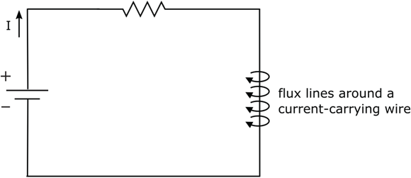
FIGURE 8-2: Current flowing through a wire produces a weak magnetic field around the wire.
Inducing current with a magnet
Hmmm … if electricity running through a wire produces a magnetic field, what happens if you place a closed loop of wire near a permanent magnet? Actually, nothing happens — unless you move the magnet. A moving magnetic field will induce a voltage across the ends of the wire, causing current to flow through the wire. Electromagnetic induction seems to make current magically appear — without any direct contact with the wire. The strength of the current depends on a lot of things, such as the strength of the magnet, the number of flux lines intercepted by the wire, the angle at which the wire cuts across flux lines, and the speed of the magnet’s motion. You can increase your chances of inducing a strong current by wrapping the wire into a coil and placing the magnet through the center (core) of the coil. The more turns of wire you wrap, the stronger the current will be.
Suppose you place a strong permanent magnet in the center of a coil of wire connected as in Figure 8-3. (Note that the multimeter and the wire form a complete path.) If you move the magnet up, current is induced in the wire and flows in one direction. If you move the magnet down, current is also induced, but it flows in the other direction. By moving the magnet up and down repeatedly, you can produce an alternating current (AC) in the wire. Alternatively, you can move the wire up and down around the magnet, and the same thing will happen. As long as there is relative motion between the wire and the magnet, current will be induced in the wire.
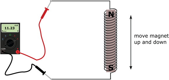
FIGURE 8-3: Moving a magnet inside a coil of wire induces a current in the wire.
 You can witness electromagnetic induction firsthand by using a relatively strong bar magnet, a length (at least 12 inches) of 22 gauge (or thinner) wire, a pencil, and your multimeter. Strip the insulation off the ends of the wire and wrap the wire in tight loops around the pencil, as shown in Figure 8-4, leaving the stripped ends accessible. With your multimeter set to measure milliamps, connect your meter leads to the wire. You’ve completed a path for current to flow, but because there is no power source, no current flows. Next, place the magnet right next to the wire. Still no current, right? Finally, move the magnet back and forth along the wire and observe the multimeter display. You should see a tiny current reading (mine was a few hundredths of a milliamp) alternating between positive and negative.
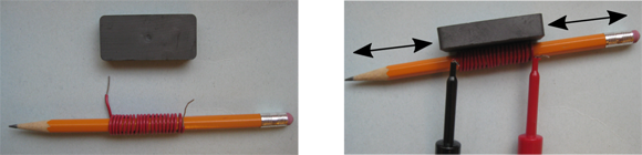
FIGURE 8-4: Moving a magnet near a coil of wire induces a current in the wire.
Many power plants generate AC by rotating conductive coils inside a strong horseshoe-shaped magnet. The coils are attached to a rotating turbine, which turns as water or steam applies pressure to its fins. As the coils make one full rotation inside the magnet, the magnet pulls electrons first in one direction and then in the other direction, producing alternating current.
Introducing the Inductor: A Coil with a Magnetic Personality
An inductor is a passive electronic component made from a coil of wire wrapped around a core — which could be air, iron, or ferrite (a brittle material made from iron). Iron-based core materials increase the strength of the magnetic field induced by current several hundred times. Inductors are sometimes known as coils, chokes, electromagnets, and solenoids, depending on how they’re used in circuits. The circuit symbol for an inductor is shown in Figure 8-5.
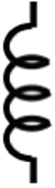
FIGURE 8-5: Circuit symbol for an inductor.
If you pass current through an inductor, you create a magnetic field around the wire. If you change the current, increasing it or decreasing it, the magnetic flux around the coil changes, and a voltage is induced across the inductor. That voltage, sometimes called back voltage, causes a current flow that opposes the main current. This property of inductors is known as self-inductance, or simply inductance.
Measuring inductance
Inductance, symbolized by L, is measured in units called henrys (named for Joseph Henry, a New Yorker who liked to play with magnets and discovered the property of self-inductance). An inductance of one henry (abbreviated H) will induce one volt when the current changes its rate of flow by one ampere per second. One henry is much too large for everyday electronics, so you’re more likely to hear about millihenrys (mH), because inductance measured in thousandths of a henry is more commonplace. You’ll also run across microhenrys (μH), which are millionths of a henry.
Opposing current changes
In Figure 8-6, a DC voltage is applied to a resistor in series with an inductor. If there were no inductor in the circuit, a current equal to Vsupply/R would flow instantaneously as soon as the DC voltage was switched on. However, introducing an inductor affects what happens to the current flowing in the circuit.

FIGURE 8-6: An inductor delays changes in current.
When the DC voltage is first switched on, the current that starts to flow induces a magnetic field around the coils of the inductor. As the current increases (which it’s trying to do instantaneously), the strength of the magnetic field increases proportionally. Because the magnetic field is changing, it induces a back voltage that in turn induces a current in the coiled wire in the opposite direction to that of the current already flowing from the voltage source. The inductor seems to be trying to prevent the source current from changing too quickly; the effect is that the current doesn’t increase instantaneously. This is why inductors are said to oppose changes in current.
The current induced in the coil reduces the strength of the expanding magnetic field a bit. As the source current keeps rising, the magnetic field continues to expand (but more and more slowly), and current opposing the source current continues to be induced (but it gets smaller and smaller). The cycle continues, until finally the overall current settles down to a steady DC. When current reaches a steady level, the magnetic field no longer changes — and the inductor ceases to affect the current in the circuit.
The overall effect is that it takes a finite amount of time for the current flowing through the inductor to reach a steady DC value. (The specific amount of time it takes depends on a few things, such as the characteristics of the inductor and the size of the resistor in the circuit. See the next section, “Calculating the RL time constant.”) When this happens, the current flows freely through the inductor, which acts like a simple wire (commonly referred to as a short circuit, or simply a short), so VL is nearly 0 V (a tiny voltage is dropped across the inductor due to the resistance of the coil’s wire) and the steady-state current is determined by the source voltage and the resistor according to Ohm’s Law ![]() .
.
If you then remove the DC voltage source and connect the resistor across the inductor, current will flow for a short period of time, with the inductor again opposing the sudden drop in current, until finally the current settles down to zero and the magnetic field disappears.
 From an energy perspective, when you apply a DC source to an inductor, it stores electrical energy in a magnetic field. When you remove the DC source and connect a resistor across the inductor, the energy is transferred to the resistor, where it dissipates as heat. Inductors store electrical energy in magnetic fields. A real inductor — as opposed to a theoretical ideal inductor — exhibits a certain amount of resistance and capacitance in addition to inductance, due to the physical properties of its windings and core material as well as the nature of magnetic fields. Consequently, an inductor (unlike a capacitor) can't retain electrical energy for very long because energy is lost through heat dissipation.
To help you understand inductors, think about water flowing through a pipe with a turbine in it. When you first apply water pressure, the fins of the turbine obstruct the flow, applying back pressure on the water. As the fins start to turn, they apply less back pressure, so the water flows more easily. If you suddenly remove the water pressure, the fins will keep turning for a while, pulling water along with them, until eventually the fins stop turning and the water stops flowing.
Don’t worry about the ins and outs of induced currents, expanding and contracting magnetic fields, and the like. Just remember a few things about inductors:
- An inductor opposes (resists) changes in current.
- An inductor acts like an open circuit when DC is first applied — that is, no current flows right away, and the entire source voltage is dropped across the inductor.
- An inductor eventually acts like a short in DC circuits — that is, when all the magnetic-field magic settles down, the voltage is zero, and the inductor allows the full DC current to pass through.
Calculating the RL time constant
You can calculate the amount of time (in seconds) it takes for the current flowing through an inductor in a resistor-inductor circuit to reach a steady DC value. To do this, you use the RL time constant, 003A4, which tells you how long it takes for the inductor to conduct roughly two-thirds of the steady DC current that results from a voltage applied across the resistor-inductor series combination. The formula looks like this:
Just as the RC time constant in RC circuits (which you can read about in Chapter 7) gives you an idea of how long it takes a capacitor to charge to its full capacity, so the RL time constant helps you figure out how long it will take for an inductor to fully conduct a DC current: Direct current settles down to a steady value after roughly five RL time constants.
Keeping up with alternating current (or not!)
When you apply an AC voltage to a circuit containing an inductor, the inductor fights against any changes in the source current. If you keep varying the supply voltage up and down at a very high frequency, the inductor will keep opposing the sudden changes in current. At the extreme high end of the frequency spectrum, no current flows at all because the inductor simply can't react quickly enough to the change in current.
Picture yourself standing between two very tempting dessert platters. You want to go for each of them, but can’t decide which to try first. You start out running toward one, but quickly change your mind and turn around and starting running toward the other. Then you change your mind again, so you turn and start racing toward the first one, and so forth. The faster you change your mind, the more you stay put in the middle — not getting anywhere (or any dessert). Those tempting desserts make you act like the electrons in an inductor when a high-frequency signal is applied to the circuit: Neither you nor the electrons make any progress.
Behaving differently depending on frequency
Like capacitors, inductors in an AC circuit act differently depending on the frequency of the voltage applied to them. Because the current passing through an inductor is affected by frequency, the voltage drops across the inductor and other components in the circuit are also affected by frequency. This frequency-dependent behavior forms the basis for useful functions, such as filters, which are circuits that allow some frequencies to pass through to another circuit stage while blocking other frequencies. When you adjust the bass and treble settings on your stereo system, you're using filters.
Here are some common types of filters:
- Low-pass filters are circuits that allow lower frequencies to pass from input to output while blocking frequencies above a particular cutoff frequency.
- High-pass filters are circuits that allow higher frequency signals to pass while blocking frequencies below the cutoff frequency.
- Band-pass filters are circuits that allow a band of frequencies — between a lower cutoff frequency and an upper cutoff frequency — to pass.
- Band-stop (or band-rejection) filters are circuits that allow every frequency except a specific band of frequencies to pass. You might use such a filter to filter out unwanted hum from a 60 Hz power line — as long as you know the frequency range of the hum.
Because inductors pass DC and block more and more AC as frequency increases, they are natural low-pass filters. In Chapter 7, you find out that capacitors block DC signals and allow AC signals to pass, so (as you might guess) they are natural high-pass filters. In electronic filter design — which is a complex topic beyond the scope of this book — components are carefully selected to precisely control which frequencies are allowed to pass through to the output.
Inductors are sort of the alter egos of capacitors. Capacitors oppose voltage changes; inductors oppose current changes. Capacitors block DC and pass more and more AC as frequency increases; inductors pass DC and block more and more AC as frequency increases.
Uses for Inductors
Inductors are used primarily in tuned circuits, to select or reject signals of specific frequencies, and to block (or choke) high-frequency signals, such as eliminating radio frequency (RF) interference in cable transmissions. In audio applications, inductors are also commonly used to remove the 60 Hz hum known as noise (often created by nearby power lines). Here’s a list that explains some of the amazing things a simple coil of wire can do:
- Filtering and tuning: Like capacitors, inductors can be used to help select or reject certain electrical signals depending upon their frequency. Inductors are often used to tune in target frequencies in radio receiver systems.
- AC motors: In an AC induction motor, two pairs of coils are energized by an AC power supply (50 or 60 Hz), setting up a magnetic field that then induces a current in a rotor placed in the center of the magnetic field. That current then creates another magnetic field that opposes the original magnetic field, causing the rotor to spin. Induction motors are commonly used in fans and household appliances.
- Blocking AC: A choke is an inductor used to prevent a signal from passing through it to another part of a circuit. Chokes are often used in radio transmission systems to prevent the transmitted signal (an AC waveform) from shorting out through the power supply. By blocking the signal from traveling through a path to ground, a choke enables the signal to follow its intended path to the antenna, where it can be transmitted.
- Contactless sensors: Many traffic-light sensors use an inductor to trigger the light to change. Embedded in the street several yards before the intersection is an inductive loop consisting of several turns of a gigantic coil, roughly six feet in diameter. This loop is connected to a circuit that controls the traffic signal. As your car passes over the loop, the steel underbody of your car changes the magnetic flux of the loop. The circuit detects this change — and gives you the green light. Metal detectors use inductors in a similar way to pick up the presence of magnetic or metallic objects.
- Smoothing out current: Inductors can be used to reduce current swings (ripple) in a power supply. As the current changes, the magnetic flux around the coil changes and a back voltage is induced across the inductor, causing a current flow that opposes the main current.
Using Inductors in Circuits
The wire that makes up an inductor is often insulated to prevent unintended short circuits between the turns. Inductors may also be shielded, or encased in a nonferrous metal can (typically brass or aluminum), to prevent the magnetic lines of flux from infiltrating the neighborhood of other components in a circuit. You use a shielded inductor when you don’t want to induce voltages or currents in other circuit elements. You use an unshielded inductor (or coil) when you do want to affect other circuit elements. I discuss the use of unshielded coils in circuits in the later section “Influencing the Coil Next Door: Transformers.”
Reading inductance values
The value of an inductor is typically marked on its package using the same color-coding technique used for resistors, which you can read about in Chapter 5. You can often find the value of larger inductors printed directly on the components. Smaller-value inductors look a lot like low-wattage resistors; such inductors and resistors even have similar color-coding marks. Larger-value inductors come in a variety of sizes and shapes each offering trade-offs in terms of performance, cost, and other factors.
Inductors can be either fixed or variable. With either type, a length of wire is wound around a core. The number of turns of the wire, the core material, the wire’s diameter, and length of the coil all determine the numerical value of the inductor. Fixed inductors have a constant value; variable inductors have adjustable values. The core of an inductor can be made of air, iron ferrite, or any number of other materials (including your car). Air and ferrite are the most common core materials.
Combining shielded inductors
Chances are, you won’t use inductors in the basic electronic circuits you set up, but you may run across circuit diagrams for power supplies and other devices that include multiple inductors. Just in case you do, you should know how to calculate the equivalent inductance of combinations of shielded inductors so you can get a clear picture of how the circuit operates.
Inductors in series add up, just as resistors do:
Like resistors, inductors in parallel combine by adding the reciprocals of each individual inductance, and then taking the reciprocal of that sum. (You may remember from math class that the reciprocal is the multiplicative inverse of a number, or the number that you multiply by so that the result equals 1. So for any integer x, 1/x is its reciprocal.)
Another way to express the preceding equation is
If you have just two inductors in parallel, you can simplify this equation as follows:
Tuning in to Radio Broadcasts
Inductors are natural low-pass filters and capacitors are natural high-pass filters, so what happens when you put the two in the same circuit? As you might guess, inductors and capacitors are often used together in tuning circuits, to tune in a specific radio station’s broadcast frequency.
Resonating with RLC circuits
Look at the RLC circuit in Figure 8-7. Now imagine what happens to the current, i, flowing through the circuit as you vary the frequency of the input signal, vin. Because the capacitor blocks DC and allows more and more alternating current (AC) to flow as frequency increases, low-frequency input signals tend to get squelched. Because the inductor passes DC and blocks more and more AC as frequency increases, high-frequency input signals are also squelched. What happens to the in-between frequencies? Well, some current is allowed to pass through, with the most current flowing when the input signal is at one specific frequency, known as the resonant frequency.
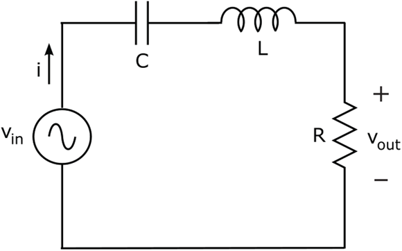
FIGURE 8-7: An RLC circuit has a resonant frequency, at which the maximum current flows.
The value of the resonant frequency, fo, depends on the values of the inductance (L) and the capacitance (C), as follows:
The circuit is said to resonate at that particular frequency, and so is known as a resonant circuit. Figure 8-8 shows a frequency plot of the current passing through the circuit; note that the current is highest at the resonant frequency.
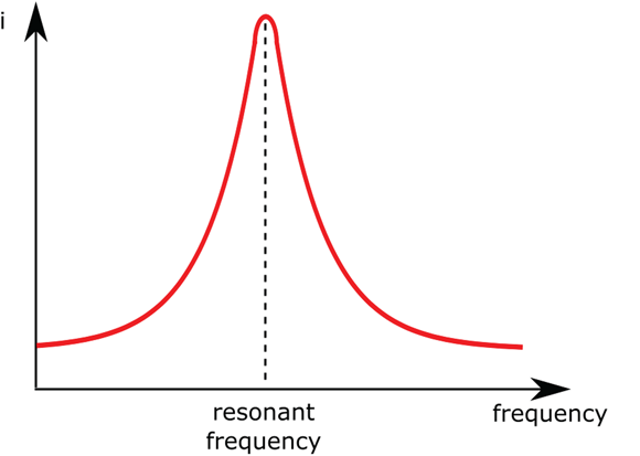
FIGURE 8-8: The current in a series RLC circuit is highest at the resonant frequency.
Analog radio receivers use RLC circuits to allow just one frequency to pass through the circuit. This process is known as tuning in to the frequency; used this way, the circuit is known as a tuning circuit. A variable capacitor is used to adjust the resonant frequency, so you can tune in different stations broadcasting at different frequencies. The knob that allows the capacitance to be changed is attached to the tuning-control knob on your radio.
A graphic equalizer uses a series of tuning circuits to separate an audio signal into several frequency bands. The slide controls on the equalizer allow you to adjust the gain (amplification) of each frequency band independently. In a later circuit stage, the individual bands are recombined into one audio signal — customized according to your taste — that is sent to your speakers.
By shifting components around a bit, you can create a variety of filter configurations. For instance, by placing the resistor, inductor, and capacitor in parallel with each other, you create a circuit that produces the minimum current at the resonant frequency. This sort of resonant circuit tunes out that frequency, allowing all others to pass, and is used to create band-stop filters. You might find such a circuit filtering out the 60 Hz hum that electronic equipment sometimes picks up from a nearby power line.
Ensuring rock-solid resonance with crystals
If you slice a quartz crystal in just the right way, mount two leads to it, and enclose it in a hermetically sealed package, you’ve created a single component that acts like an RLC combo in an RLC circuit, resonating at a particular frequency. Quartz crystals, or simply crystals, are used in circuits to generate an electrical signal at a very precise frequency. Figure 8-9 shows the circuit symbol for a crystal, which is labeled XTAL in schematics.

FIGURE 8-9: Circuit symbol for a crystal.
Crystals work because of something called the piezoelectric effect: If you apply a voltage in just the right way across a quartz crystal, it vibrates at a specific frequency, known as the resonant frequency. If you then remove the applied voltage, the crystal continues to vibrate until it settles back to its previous shape. As it vibrates, it generates a voltage at the resonant frequency.
You may be familiar with piezoelectric guitar pickups, which use crystals to convert the mechanical vibrations generated by guitar strings into electrical signals, which are then amplified. And if you predate compact disc (CD) technology, you may be interested to know that phonograph needles relied on the piezoelectric effect to convert the ups and downs of a vinyl record track into electrical energy.
The frequency at which a crystal resonates depends on its thickness and size, and you can find crystals with resonant frequencies ranging from a few tens of kilohertz to tens of megahertz. Crystals are more precise and more reliable than combinations of capacitors and inductors, but there’s a catch: They’re usually more expensive. You will find crystals used in circuits called oscillators to generate electric signals at a very precise frequency. Oscillators are responsible for the ticks and tocks that control quartz wristwatches and digital integrated circuits (which I discuss in Chapter 11), and for controlling the accuracy of radio equipment.
A quartz crystal is accurate to within roughly 0.001% of its stated resonant frequency. (That’s why they’re worth paying some extra bucks for!) You may also hear of ceramic resonators, which work the same way but cost less and are not as accurate as quartz. Ceramic resonators have a 0.5% frequency tolerance — meaning that the actual resonant frequency can vary by as much as 0.5% above or below its stated resonant frequency — and are used in many consumer-electronics devices, such as TVs, cameras, and toys.
Influencing the Coil Next Door: Transformers
Inductors used in tuning circuits are shielded so that the magnetic field they produce doesn’t interact with other circuit components. Unshielded coils are sometimes placed close to one another for the express purpose of allowing their magnetic fields to interact. In this section, I describe how unshielded coils interact — and how you can exploit their interaction to do some useful things with an electronic device known as a transformer.
Letting unshielded coils interact
When you place two unshielded coils near each other, the varying magnetic field created as a result of passing AC through one coil induces a voltage in that coil as well as in the other coil. Mutual inductance is the term used to describe the effect of inducing a voltage in another coil, while self-inductance refers to the effect of inducing a voltage in the same coil that produced the varying magnetic field in the first place. The closer the coils, the stronger the interaction. Mutual inductance can add to or oppose the self-inductance of each coil, depending on how you match up the north and south poles of the inductors.
If you have an unshielded coil in one circuit, and place it close to an unshielded coil in another circuit, the coils will interact. By passing a current through one coil, you will cause a voltage to be induced in the neighboring coil — even though it is in a separate, unconnected circuit. This is known as transformer action.
A transformer is an electronic device that consists of two coils wound around the same core material in such a way that the mutual inductance is maximized. Current passing through one coil, known as the primary, induces a voltage in the other coil, known as the secondary. The job of a transformer is to transfer electrical energy from one circuit to another.
The circuit symbols for an air-core transformer and solid-core transformer, respectively, are shown in Figure 8-10.
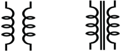
FIGURE 8-10: Circuit symbols for an air-core transformer and a solid-core transformer.
Isolating circuits from a power source
If the number of turns of wire in the primary winding of a transformer is the same as the number of turns in the secondary winding, theoretically, all of the voltage across the primary will be induced across the secondary. This is known as a 1:1 transformer, because there is a 1:1 (read “one-to-one”) relationship between the two coils. (In reality, no transformer is perfect, or lossless, and some of the electrical energy gets lost in the translation.)
A 1:1 transformer is also known as an isolation transformer, and is commonly used to electrically separate two circuits while allowing AC power or an AC signal from one to feed into the other. The first circuit typically contains the power source, and the second circuit contains the load. (You find out in Chapter 1 that the load is the destination for the electrical energy, or the thing you ultimately want to perform work on, such as a speaker diaphragm.) You may want to isolate circuits to reduce the risk of electrical shocks or to prevent one circuit from interfering with the other.
Stepping up, stepping down voltages
If the number of turns in the primary winding of a transformer is not the same as the number of turns in the secondary winding, the voltage induced in the secondary will be different from the voltage across the primary. The two voltages will be proportional to each other, with the proportion determined by the ratio of the number of turns in the secondary to the number of turns in the primary, as follows:
In this equation, VS is the voltage induced in the secondary, VP is the voltage across the primary, NS is the number of turns in the secondary, and NP is the number of turns in the primary.
Say, for instance, that the secondary consists of 200 turns of wire — twice as many as the primary, which consists of 100 turns of wire. If you apply an AC voltage with a peak value of 50 V to the primary, the peak voltage induced across the secondary will be 100 V, or twice the value of the peak voltage across the primary. This type of transformer is known as a step-up transformer, because it steps up the voltage from the primary to the secondary.
If, instead, the secondary consists of 50 turns of wire, and the primary consists of 100 turns, the same AC signal applied to the same primary has a different result: The peak voltage across the secondary would be 25 V, or half the primary’s voltage. This is known as a step-down transformer, for obvious reasons.
In each case, the power applied to the primary winding is transferred to the secondary. Because power is the product of voltage and current ![]() , the current induced in the secondary winding is inversely proportional to the voltage induced in the secondary. So a step-up transformer steps up the voltage while stepping down the current; a step-down transformer steps down the voltage while stepping up the current.
, the current induced in the secondary winding is inversely proportional to the voltage induced in the secondary. So a step-up transformer steps up the voltage while stepping down the current; a step-down transformer steps down the voltage while stepping up the current.
Step-up and step-down transformers are used in electrical power-transmission systems. Electricity generated at a power plant is stepped up to voltages of 110 kV ![]() or more, transported over long distances to a substation, and then stepped down to lower voltages for distribution to customers.
or more, transported over long distances to a substation, and then stepped down to lower voltages for distribution to customers.