
Chapter 5
Meeting Up with Resistance
IN THIS CHAPTER
![]() Using resistance to your advantage
Using resistance to your advantage
![]() Varying the amount of resistance
Varying the amount of resistance
![]() Creating just the right amount of resistance
Creating just the right amount of resistance
![]() Realizing why LEDs need resistors
Realizing why LEDs need resistors
If you toss a marble into a sandbox, the marble won’t go very far. But if you toss a marble onto the surface of a large frozen lake, the marble will enjoy a nice little ride before it eventually comes to a stop. A mechanical force called friction stops that marble on either surface — it’s just that the sand provides more friction than the ice.
Resistance in electronics is a lot like friction in mechanical systems: It puts the brakes on electrons (those microscopic moving particles that make up electric current) as they move through materials.
In this chapter, you take a look at exactly what resistance is, where you can find resistance (everywhere), and how you can use it to your advantage by selecting resistors (components that provide controlled amounts of resistance) for your electronic circuits. Then you discover how to combine resistors to control current in your circuits. Next, you build and explore a few circuits using resistors and light-emitting diodes (LEDs). Finally, you discover just how important resistors are — and what happens when a critical resistor goes AWOL.
Resisting the Flow of Current
Resistance is a measure of an object’s opposition to the flow of electrons. This may sound like a bad thing, but it’s actually useful. Resistance is what makes it possible to generate heat and light, restrict the flow of electric current when necessary, and ensure that the correct voltage is supplied to a device. For instance, as electrons travel through the filament of an incandescent light bulb, they meet so much resistance that they slow down a lot. As they fight their way through the filament, the atoms of the filament bump into each other furiously, generating heat — which produces the glow that you see from your light bulb.
Everything — even the best conductors — exhibits a certain amount of resistance to the flow of electrons. (Well, actually, certain materials, called superconductors, can conduct current with zero electrical resistance — but only if you cool them down to extremely low temperatures. You won’t encounter them in conventional electronics.) The higher the resistance, the more restricted the flow of current.
So what determines how much resistance an object has? Resistance depends on several factors:
- Material: Some materials allow their electrons to roam freely, whereas others hold on tight to their electrons. Just how strongly a specific material opposes the flow of electrons determines its resistivity. Resistivity is a property of a material that reflects its chemical structure. Conductors have relatively low resistivity, whereas insulators have relatively high resistivity.
- Cross-sectional area: Resistance varies inversely with cross-sectional area; the larger the diameter, the easier it is for electrons to move — that is, the lower the resistance to their movement. Think of water flowing through a pipe: The wider the pipe, the easier the water flows. Along the same lines, a copper wire with a large diameter has lower resistance than a copper wire with a small diameter.
- Length: The longer the material, the more resistance it has because electrons have more opportunities to bump into other particles along the way. In other words, resistance varies directly with length.
- Temperature: For most materials, the higher the temperature, the higher the resistance. Higher temperatures mean that the particles inside have more energy, so they bump into each other a lot more, slowing down the flow of electrons. One notable exception to this is a type of resistor called a thermistor: Increase the temperature of a thermistor, and it lowers its resistance in a predictable way. (You can imagine how useful that characteristic is in temperature-sensing circuits.) You can read about thermistors in Chapter 12.
 You use the symbol R to represent resistance in an electronic circuit. Sometimes you’ll see a subscript next to a resistance, for instance, Rbulb. That just means that Rbulb represents the resistance of the light bulb (or whatever part of the circuit the subscript refers to). Resistance is measured in units called ohms (pronounced “omes”), abbreviated with the Greek letter omega (Ω). The higher the ohm value, the higher the resistance.
 A single ohm is so small a unit of resistance that you’re likely to see resistance measured in larger quantities, such as kilohms (kilo + ohm), which is thousands of ohms and is abbreviated kΩ, or megohms (mega + ohm), which is millions of ohms and is abbreviated MΩ. So 1 kΩ = 1,000 Ω and 1 MΩ = 1,000,000 Ω.
Resistors: Passive Yet Powerful
Resistors are passive electronic components that are specially designed to provide controlled amounts of resistance (for instance, 470 Ω or 1 kΩ). (Refer to Figure 5-1.)

FIGURE 5-1: Resistors come in a variety of sizes and resistance values.
Although a resistor won’t boost current or control its direction (because it’s passive), you'll find it to be a powerful little device because it enables you to put the brakes on current flow in a controlled way. By carefully choosing and arranging resistors in different parts of your circuit, you can control just how much — or how little — current each part of your circuit gets.
What are resistors used for?
Resistors are among the most popular electronic components around because they’re simple yet versatile. One of the most common uses of a resistor is to limit the amount of current in part of a circuit. However, resistors can also be used to control the amount of voltage provided to part of a circuit and to help create timing circuits.
Limiting current
The circuit in Figure 5-2 shows a 6-volt battery supplying current to a light-emitting diode (LED) through a resistor (shown as a zigzag). LEDs (like many other electronic parts) eat up current like a kid eats candy: They try to gobble up as much as you give them. But LEDs run into a problem — they burn themselves out if they draw too much current. The resistor in the circuit serves the useful function of limiting the amount of current sent to the LED (the way a good parent restricts the intake of candy).
Too much current can destroy many sensitive electronic components — such as transistors (which I discuss in Chapter 10) and integrated circuits (which I discuss in Chapter 11). By putting a resistor at the input to a sensitive part, you limit the current that reaches the part. (But if you use too high a resistance, say 1 MΩ, which is 1,000,000 ohms, you’ll limit the current so much you won’t see the light, although it’s there!) This simple technique can save you a lot of time and money that you would otherwise lose fixing accidental blow-ups of your circuits.
You can observe how resistors limit current by setting up the circuit shown in Figure 5-2 and trying out resistors of different values. In the “Reading into fixed resistors” section, later in the chapter, I tell you how to decode the stripes on a resistor to determine its value. For now, I tell you what the ones you need look like.
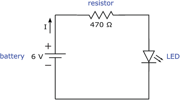
FIGURE 5-2: The resistor limits the amount of current, I, flowing into sensitive components, such as the light-emitting diode (LED) in this circuit.
Here’s what you use to build the LED-resistor circuit:
- Four 1.5-volt AA batteries
- One four-battery holder (for AA batteries)
- One battery clip
- One 470 Ω resistor (identified by yellow-violet-brown stripes and then a fourth stripe which may be gold, silver, black, brown, or red)
- One 4.7 kΩ resistor (yellow-violet-red and any color for the fourth stripe)
- One 10 kΩ resistor (brown-black-orange and any color for the fourth stripe)
- One 47 kΩ resistor (yellow-violet-orange and any color for the fourth stripe)
- One LED (any size, any color)
- Three insulated alligator clips or one solderless breadboard
Use alligator clips or a solderless breadboard to set up the circuit (see Figure 5-3), starting with the 470 Ω resistor. Remember to orient the LED correctly, connecting the shorter lead of the LED to the negative battery terminal. Don’t worry about the orientation of the resistor; either way is fine. Note how brightly the LED shines. Then remove the resistor and replace it with the other resistors, one at a time, increasing the amount of resistance each time. Did you notice that the LED shines less brightly each time? That’s because higher resistances restrict current more, and the less current an LED receives, the less brightly it shines.
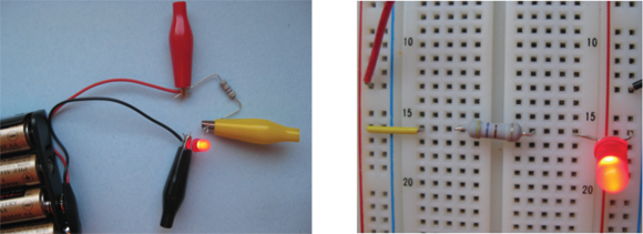
FIGURE 5-3: Two ways to set up the resistor-LED circuit.
Figure 5-4 shows a parallel circuit (described in Chapter 4) in which each branch contains a different value of resistance. For higher values of resistance, the current that passes through that branch is restricted more, so the LED in that branch emits less light.

FIGURE 5-4: Higher values of resistance restrict current more, resulting in less light emitted from the LEDs.
Reducing voltage
Resistors can be used also to reduce the voltage supplied to different parts of a circuit. Say, for instance, you have a 9-volt power supply but you need to provide 5 volts to power a particular integrated circuit you’re using. You can set up a circuit, such as the one shown in Figure 5-5, to divide the voltage in a way that provides 5 V at the output. Then — voilà — you can use the output voltage, Vout, of this voltage divider as the supply voltage for your integrated circuit. (You find details of how this works in Chapter 6.)
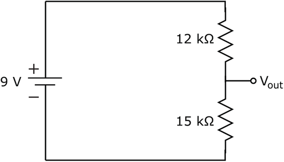
FIGURE 5-5: Use two resistors to create a voltage divider, a common technique for producing different voltages for different parts of a circuit.
To observe the voltage divider in action, set up the circuit shown in Figure 5-6 by using the following parts:
- One 9-volt battery
- One battery clip
- One 12 kΩ resistor (brown-red-orange and any color for the fourth stripe)
- One 15 kΩ resistor (brown-green-orange and any color for the fourth stripe)
- Three insulated alligator clips or one solderless breadboard

FIGURE 5-6: Two ways to build the voltage divider circuit.
Next, use your multimeter set to volts DC to measure the voltage across the battery and across the 15 kΩ resistor, as shown in Figure 5-7. My measurements show that the actual battery voltage is 9.24 V and Vout (the voltage across the 15 kΩ resistor) is 5.15 V.
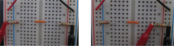
FIGURE 5-7: Measure the total voltage supplied by the battery (left) and the voltage across the 15 kΩ resistor (right).
Controlling timing cycles
You can also put a resistor to work with another popular component — a capacitor, which I discuss in Chapter 7 — to create predictable up and down voltage swings. You’ll find the resistor-capacitor combo helps you create a kind of hourglass timer, which comes in handy for circuits that have time dependencies (for instance, a three-way traffic light). I show how the dynamic duo of resistor and capacitor operates in Chapter 7.
Choosing a type of resistor: Fixed or variable
Resistors come in two basic flavors: fixed and variable. Both types are commonly used in electronic circuits. Here’s the lowdown on each type and why you would choose one or the other:
- A fixed resistor supplies a constant, factory-determined resistance. You use it when you want to restrict current to within a certain range or divide voltage in a particular way. Circuits with LEDs use fixed resistors to limit the current, thus protecting the LED from damage.
- A variable resistor, commonly called a potentiometer (pot for short), allows you to adjust the resistance from virtually zero ohms to a factory-determined maximum value. You use a potentiometer when you want to vary the amount of current or voltage you’re supplying to part of your circuit. A few examples of where you might find potentiometers are light-dimmer switches, volume controls for audio systems, and position sensors, although digital controls have largely replaced potentiometers in consumer electronics.
In this section, you take a closer look at fixed and variable resistors. Figure 5-8 shows the circuit symbols that are commonly used to represent fixed resistors, potentiometers, and another type of variable resistor called a rheostat. (See the sidebar “Recognizing rheostats,” later in this chapter.) The zigzag pattern should remind you that resistors make it more difficult for current to pass through, just as a kink in a hose makes it more difficult for water to pass through.

FIGURE 5-8: Circuit symbols for a fixed resistor (left), potentiometer (center), and rheostat (right).
Fixed resistors
Fixed resistors are designed to have a specific resistance, but the actual resistance of any given resistor may vary (up or down) from its nominal value by some percentage, known as the resistor’s tolerance.
Say you choose a 1,000 Ω resistor that has a 5% tolerance. The actual resistance it provides could be anywhere from 950 Ω to 1,050 Ω (because 5% of 1,000 is 50). You might say that the resistance is 1,000 Ω, give or take 5%.
I used my multimeter set to ohms to measure the actual resistance of five 1 k Ω, 5% tolerance resistors. These were the readings: 985 Ω, 980 Ω, 984 Ω, 981 Ω, and 988 Ω.
There are two categories of fixed resistors:
- Standard-precision resistors can vary anywhere from 2% to (gulp) 20% of their nominal values. Markings on the resistor package will tell you just how far off the actual resistance may be (for instance, ±2%, ±5%, ±10%, or ±20%). You use standard-precision resistors in most hobby projects because (more often than not) you’re using resistors to limit current or divide voltages to within an acceptable range. Resistors with 5% or 10% tolerance are commonly used in electronic circuits.
- High-precision resistors come within just 1% of their nominal value. You use these in circuits where you need extreme accuracy, as in a precision timing or voltage reference circuit.
Fixed resistors often come in a cylindrical package with two leads sticking out (refer to Figure 5-1) so you can connect them to other circuit elements. (see the “Identifying resistors on circuit boards” sidebar for exceptions.) Feel free to insert fixed resistors either way in your circuits — there’s no left or right, up or down, or to or from when it comes to these little two-terminal devices.
Most fixed resistors are color-coded with their nominal value and tolerance (see the “Reading into fixed resistors” section), but some resistors have their values stamped right onto the tiny package, along with a bunch of other letters and numbers guaranteed to cause confusion. If you aren’t sure of the value of a specific resistor, pull out your multimeter, set it to measure resistance in ohms, and place its probes across the resistor (either way), as shown in Figure 5-9. Make sure your resistor is not wired into a circuit when you measure its resistance; otherwise, you won’t get an accurate reading.
Circuit designs usually tell you the safe resistor tolerance to use, whether for each individual resistor or for all the resistors in the circuit. Look for a notation in the parts list or as a footnote in the circuit diagram. If the schematic doesn’t state a tolerance, you can assume it’s okay to use standard-tolerance resistors (±5% or ±10%).
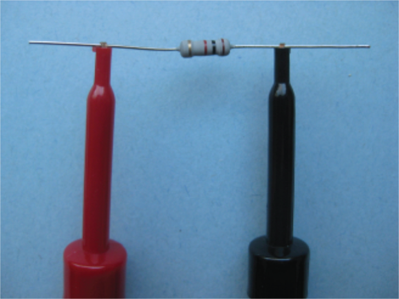
FIGURE 5-9: Use your multimeter set on ohms to measure the actual resistance of a fixed resistor.
Reading into fixed resistors
The attractive rainbow colors adorning most fixed resistors serve a purpose beyond catching your eye. Color-coding identifies the nominal value and tolerance of most resistors; the others are drab and boring, and have their values stamped on them. The color code starts near the edge of one side of the resistor and consists of several stripes, or bands, of color. Each color represents a number, and the position of the band indicates how you use that number.
Standard-precision resistors use four color bands: The first three bands indicate the nominal value of the resistor, and the fourth indicates the tolerance. Using Table 5-1, you can decipher the nominal value and tolerance of a standard-precision resistor as follows:
- The first band gives you the first digit.
- The second band gives you the second digit.
- The third band gives you the multiplier as the number of zeros to tack on to the end of the first two digits — except if the band is gold or silver.
- If the third band is gold, take the first two digits and divide by 10.
- If the third band is silver, take the first two digits and divide by 100.
- The fourth band tells you the tolerance, as shown in the fourth column of Table 5-1. If there is no fourth band, you can assume the tolerance is ±20%.
You get the nominal value of the resistance in ohms by putting the first two digits together (side by side) and applying the multiplier.
TABLE 5-1 Resistor Color Coding
Color |
Band 1 (First Digit) |
Band 2 (Second Digit) |
Band 3 (Multiplier, or Number of Zeros) |
Band 4 (Tolerance) |
Black |
0 |
0 |
100 = 1 (no zeros) |
±20% |
Brown |
1 |
1 |
101 = 10 (1 zero) |
±1% |
Red |
2 |
2 |
102 = 100 (2 zeros) |
±2% |
Orange |
3 |
3 |
103 = 1,000 (3 zeros) |
±3% |
Yellow |
4 |
4 |
104 = 10,000 (4 zeros) |
±4% |
Green |
5 |
5 |
105 = 100,000 (5 zeros) |
– |
Blue |
6 |
6 |
106 = 1,000,000 (6 zeros) |
– |
Violet |
7 |
7 |
107 = 10,000,000 (7 zeros) |
– |
Gray |
8 |
8 |
108 = 100,000,000 (8 zeros) |
– |
White |
9 |
9 |
109 = 1,000,000,000 (9 zeros) |
– |
Gold |
– |
0.1 (divide by 10) |
±5% |
|
Silver |
– |
0.01 (divide by 100) |
±10% |
Take a look at a couple of examples:
- Red-red-yellow-gold: A resistor with red (2), red (2), yellow (4 zeros), and gold (±5%) bands (see Figure 5-10, top) provides a nominal resistance of 220,000 Ω, or 220 kΩ, which could vary up or down by as much as 5% of that value. So it could have a resistance of anywhere between 209 kΩ and 231 kΩ.
- Brown-black-gold-silver: A resistor with brown (1), black (0), gold (0.1), and silver (±10%) bands (see Figure 5-10, bottom) provides a resistance of 10 × 0.1, or 1 Ω, which could vary by up to 10% of that value. So the actual resistance could be anywhere from 0.9 Ω to 1.1 Ω.
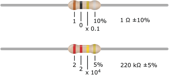
FIGURE 5-10: Decode the resistor’s stripe pattern to determine the resistance.
A resistor with five bands of color is a high-precision resistor. The first three bands of color give you the first three digits, the fourth band gives you the multiplier, and the fifth band represents the tolerance (typically ±1%).
Colors vary greatly on resistor packaging, and some resistors don’t use the color code at all, so you’d be wise to verify the actual resistance by using a multimeter set to ohms.
Variable resistors (potentiometers)
Potentiometers, or pots, allow you to adjust resistance continuously. Pots are three-terminal devices, meaning that they provide three places to connect to the outside world. (See Figure 5-11.) Between the two outermost terminals is a fixed resistance — the maximum value of the pot. Between the center terminal and either end terminal is an amount of resistance that varies depending on the position of a rotatable shaft or other control mechanism on the outside of the pot.

FIGURE 5-11: You vary the resistance of these 10 kΩ dial pots by rotating a shaft.
Inside a potentiometer is a resistance track with connections at both ends and a wiper that moves along the track. (See Figure 5-12.) Each end of the resistance track is electrically connected to one of the two end terminals on the outside of the pot, which is why the resistance between the two end terminals is fixed and equal to the maximum value of the pot.
The wiper inside the pot is electrically connected to the center terminal and mechanically connected to a shaft, slide, or screw, depending on the type of potentiometer. As you move the wiper, the resistance between the center terminal and one end terminal varies from 0 (zero) up to the maximum value, while the resistance between the center terminal and the other end terminal varies from the maximum value down to 0 (zero). Not surprisingly, the sum of the two variable resistances always equals the fixed maximum resistance (that is, the resistance between the two end terminals).

FIGURE 5-12: A potentiometer has a wiper that moves along a resistance track.
Most often, potentiometers are marked with their maximum value — 10 kΩ, 50 kΩ, 100 kΩ, 1 MΩ, and so forth — and they don’t always include the little ohm symbol (Ω). For example, with a 50 k pot, you can dial up any resistance from 0 to 50,000 Ω.
Potentiometers are available in various packages known as dial pots, slide pots, and trim pots:
- Dial pots contain rotary resistance tracks and are controlled by turning a shaft or knob. Commonly used in electronics projects, dial pots are designed to be mounted through a hole cut in a case that houses a circuit, with the knob accessible from outside the case. Dial pots are popular for adjusting volume in sound circuits.
- Slide pots contain a linear resistance track and are controlled by moving a slide along the track. You see them on stereo equipment (for instance, faders) and some dimmer switches.
- Trim pots (also known as preset pots) are smaller, are designed to be mounted on a circuit board, and provide a screw for adjusting resistance. They are typically used to fine-tune a circuit — for instance, to set the sensitivity of a light-sensitive circuit — rather than to allow for variations (such as volume adjustments) during the operation of a circuit.
 If you use a potentiometer in a circuit, bear in mind that if the wiper is dialed down all the way, you have zero resistance, and you aren't limiting current with this device. It's common practice to insert a fixed resistor in series with a potentiometer as a safety net to limit current. You just choose a value for the fixed resistor so it works with your variable resistor to produce the range of resistance you need. (Look for details about figuring out the total resistance of multiple resistors in series in the “Combining Resistors” section, later in this chapter.)
Note that the range on the potentiometer is approximate. If the potentiometer lacks markings, use a multimeter (set to ohms) to figure out the component’s value. You can also use a multimeter to measure the variable resistance between the center terminal and either end terminal. (Chapter 16 explains in detail how to test resistances using a multimeter.)
The circuit symbol commonly used to represent a potentiometer (refer to Figure 5-8, center) consists of a zigzag pattern representing the resistance and an arrow representing the wiper.
Rating resistors according to power
Quiz time! What do you get when you let too many electrons pass through a resistor at the same time? If you answered “a charred mess and no money-back guarantee,” you’re right! Whenever electrons flow through something with resistance, they generate heat — and the more electrons, the higher the heat.
Electronic components (such as resistors) can stand only so much heat (just how much depends on the size and type of component) before they have a meltdown. Because heat is a form of energy, and power is a measure of the energy consumed over a period of time, you can use the power rating of an electronic component to tell you how many watts (what? Watts, abbreviated W, are units of electric power) a component can safely handle.
All resistors (including potentiometers) come with power ratings. Standard, run-of-the-mill fixed resistors can handle 1/8 W or 1/4 W, but you can easily find 1/2 W and 1 W resistors — and some are even flameproof. (Does that make you nervous about building circuits?) Of course, you won’t see the power rating indicated on the resistor itself (that would make it too easy), so you have to figure it out by the size of the resistor (the bigger the resistor, the more power it can handle) or get it from the manufacturer or your parts supplier.
So how do you use the power rating to choose a particular resistor for your circuit? You estimate the peak power that your resistor will be expected to handle, and choose a power rating that meets or exceeds it. Power is calculated as follows:
V represents the voltage (in volts, abbreviated V) measured across the resistor and I represents the current (in amps, abbreviated A) flowing through the resistor. For example, suppose the voltage is 5 V and you want to pass 25 mA (milliamps) of current through the resistor. To calculate the power, first you convert 25 mA to 0.025 A (remember, milliamps are thousandths of an amp). Then you multiply 5 by 0.025, and you get 0.125 W, or 1/8 W. So you know that a 1/8 W resistor may be okay, but you can be sure that a 1/4 W resistor will take the heat just fine in your circuit.
For most hobby electronics projects, 1/4 W or 1/8 W resistors are fine. You need high-wattage resistors for high-load applications, where loads, such as a motor or a lamp control, require higher-than-hobby-level currents to operate. High-wattage resistors take many forms, but you can bet they are bigger and bulkier than your average resistor. Resistors with power ratings over 5 W are wrapped in epoxy (or another waterproof and flameproof coating) and have a rectangular, rather than cylindrical, shape. A high-wattage resistor may even include its own metal heat sink, with fins that conduct heat away from the resistor.
Combining Resistors
When you start shopping for resistors, you’ll find that you can’t always get exactly what you want. It would be impractical for manufacturers to make resistors with every possible value of resistance. Instead, they make resistors with a limited set of resistance values, and you work around it (as you’re about to see). For instance, you can search far and wide for a 25 kΩ resistor, but you may never find it; however, 22 kΩ resistors are as common as the day is long! The trick is to figure out how to get the resistance you need using standard available parts.
As it turns out, you can combine resistors in various ways to create an equivalent resistance value that will come pretty darn close to whatever resistance you need. And because standard precision resistors are accurate to 5%–10% of their nominal value anyway, combining resistors works out just fine.
There are certain “rules” for combining resistances, which I cover in this section. Use these rules not only to help you choose off-the-shelf resistors for your own circuits, but also as a key part of your effort to analyze other people’s electronic circuits. For instance, if you know that a light bulb has a certain amount of resistance, and you place a resistor in series with the bulb to limit the current, you’ll need to know what the total resistance of the two components is before you can calculate the current passing through them.
Resistors in series
When you combine two or more resistors (or resistances) in series, you connect them end to end (as shown in Figure 5-13), so that the same current passes sequentially through each resistor. By doing this, you restrict the current somewhat with the first resistor, you restrict it even more with the next resistor, and so forth. So the effect of the series combination is an increase in the overall resistance.
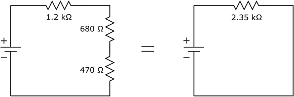
FIGURE 5-13: The combined resistance of two or more resistors in series is the sum of the individual resistances.
To calculate the combined (equivalent) resistance of multiple resistors in series, you simply add the values of the individual resistances. You can extend this rule to any number of resistances in series:
R1, R2, R3, and so forth represent the values of the resistors, and Rseries represents the total equivalent resistance. Remember that the same current flows through all resistors connected in series and that all the resistors contribute to the overall restriction of the current.
You can apply this concept of equivalent resistance to help you select resistors for a specific circuit need. For example, suppose you need a 25 kΩ resistor, but cannot find a standard resistor with that value. You can combine two standards resistors — a 22 kΩ resistor and a 3.3 kΩ resistor — in series to get 25.3 kΩ of resistance. That’s less than 2% different from the 25 kΩ you seek — well within typical resistor tolerance levels (which are 5%–10%).
Be careful with your units of measurement when you add resistance values. For example, suppose you connect the following resistors in series: 1.2 kΩ, 680 Ω, and 470 Ω. (Refer to Figure 5-13.) Before you add the resistances, you need to convert the values to the same units, for instance, ohms. In this case, the total resistance, Rseries, is calculated as follows:

The combined resistance will always be greater than any individual resistances. This fact comes in handy when you’re designing circuits. For example, if you want to limit current going into a light bulb but don’t know the resistance of the bulb, you can place a resistor in series with the bulb and be secure in the knowledge that the total resistance to current flow is at least as much as the value of the resistor you added. For circuits that use variable resistors (such as a light-dimmer circuit), putting a fixed resistor in series with the variable resistor guarantees that the current will be limited even if the pot is dialed down to zero ohms. (The lowdown on how to calculate just what the current will be for a given voltage/resistance combo appears later in this chapter.)
See for yourself how a small series resistor can save an LED. Set up the circuit shown in Figure 5-14, left, using the following parts:
- One 9-volt battery
- One battery clip
- One 470 Ω resistor (yellow-violet-brown)
- One 10 kΩ potentiometer
- Four alligator clips
- One LED, any size, any color
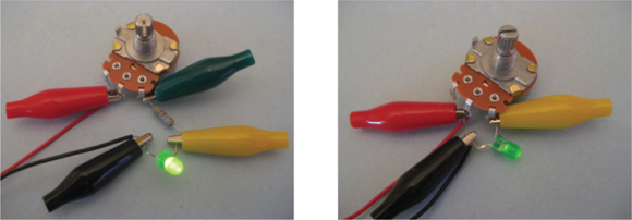
FIGURE 5-14: A resistor in series with a potentiometer ensures that current to the LED is restricted even if the pot is dialed down to zero ohms. Without that resistor, the LED is toast.
Be sure to connect the center and one end terminal of the potentiometer into the circuit, leaving the other terminal unconnected, and to orient the LED correctly, so that its shorter lead is connected to the negative battery terminal.
Rotate the shaft of the potentiometer and observe what happens to the LED. You should see the light vary in intensity from fairly bright to very dim (or vice versa) as you adjust the resistance of the pot.
With the potentiometer shaft positioned somewhere in the middle of its range, remove the 470 Ω resistor and connect the LED directly to the potentiometer, as shown in Figure 5-14, right. Now rotate the shaft slowly in the direction that makes the light grow brighter. Rotate it all the way to the end and observe what happens to the LED. As you dial the pot down to 0 Ω, you should see the LED get brighter and brighter until finally it stops shining completely. With no resistance to limit current, the LED could burn out. (If it does, you should throw it away because it won’t work anymore.)
Resistors in parallel
When you combine two resistors in parallel, you connect both sets of ends together (see Figure 5-15) so each resistor has the same voltage. By doing so, you provide two different paths for current to flow. Even though each resistor is restricting current flow through one circuit path, there’s still another path that can draw additional current. From the perspective of the source voltage, the effect of arranging resistors in parallel is a decrease in the overall resistance.

FIGURE 5-15: The combined resistance of two or more resistors in parallel is always lower than any of the individual resistances.
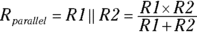
To calculate the equivalent resistance, Rparallel, of two resistors in parallel, you use the following formula:
where R1 and R2 are the values of the individual resistors.
You may remember that the line separating the numerator and the denominator in a fraction represents division, so another way to think of this formula is like this:
In the example in Figure 5-14, two 2 kΩ resistors are placed in parallel. The equivalent resistance is as follows:

In this example, because the two resistors have equal resistance, connecting them in parallel results in an equivalent resistance of half the value of either one. The result is that each resistor draws half the supply current. If two resistors of unequal value are placed in parallel, more current will flow through the path with the lower resistance than the path with the higher resistance.
If your circuit calls for a resistor with a somewhat higher power rating, say 1 W, but you have only 1/2 W resistors on hand, you can combine two 1/2 W resistors in parallel instead. Just select resistor values that combine to create the resistance you need. Because each one draws half the current that a single resistor would draw, it dissipates half the power (remember that power = voltage × current).
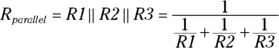
If you combine more than one resistor in parallel, the math gets a little more complicated:
The ellipsis at the end of the denominator indicates that you keep adding the reciprocals of the resistances for as many resistors as you have in parallel.
For multiple resistances in parallel, the amount of current flowing through any given branch is inversely proportional to the resistance in that branch. In practical terms, the higher the resistance, the less current goes that way; the lower the resistance, the more current goes that way. Just like water, electric current favors the path of least resistance.
As a shorthand in electronic equations, you may see the symbol || used to represent the formula for resistors in parallel. For example:
- or
Combining series and parallel resistors
Many circuits combine series resistors and parallel resistors in various ways to restrict current in some parts of the circuit while splitting current in other parts of the circuit. In some cases, you can calculate equivalent resistance by combining the equations for resistors in series and resistors in parallel.
For instance, in Figure 5-16, resistor R2 (3.3 kΩ) is in parallel with resistor R3 (3.3 kΩ), and that parallel combination is in series with resistor R1 (1 kΩ). You can calculate the total resistance (in kΩ) as follows:
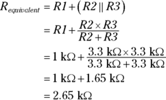

FIGURE 5-16: Many circuits include a combination of parallel and series resistances.
In this circuit, the current supplied by the battery is limited by the total resistance of the circuit, which is 2.65 kΩ. Supply current flows from the positive battery terminal through resistor R1, splits — with half flowing through resistor R2 and half flowing through resistor R3 (because those resistances are the same) — and then combines again to flow into the negative battery terminal.
Circuits often have more complex combinations of resistances than simple series or parallel relationships, and figuring out equivalent resistances isn’t always easy. You have to use matrix mathematics to analyze them, and because this book isn’t a math book, I'm not going to detour to explore the complexities of matrix math.