
Chapter 9
Diving into Diodes
IN THIS CHAPTER
![]() Peeking inside a semiconductor
Peeking inside a semiconductor
![]() Fusing two semiconductors to make a diode
Fusing two semiconductors to make a diode
![]() Letting current flow this way but not that way
Letting current flow this way but not that way
Semiconductors are at the heart of nearly every major electronic system that exists today, from the programmable pacemaker to your smartphone to the space shuttle. It’s amazing to think that teeny-tiny semiconductor devices are responsible for triggering enormous advances in modern medicine, space exploration, industrial automation, home entertainment systems, communications, and a slew of other industries.
The simplest type of semiconductor device, called a diode, can be made to conduct or block electric current and to allow current to flow in one direction but not the other — depending on how you control it electrically.
This chapter explains what semiconductors are, how to make them conduct current, and how to combine two semiconductors to create a diode. Then you get an eyewitness view of the valve-like behavior of diodes — and take a look at how to exploit that behavior to accomplish amazing things in circuits.
Are We Conducting or Aren’t We?
Somewhere between insulators and conductors are materials that can’t seem to make up their minds about whether to hold on to their electrons or let them roam freely. These semiconductors behave like conductors under some conditions and like insulators under other conditions, giving them unique capabilities.
With a device made from semiconductor materials, such as silicon or germanium, you can precisely control the flow of electrical charge carriers in one area of the device by adjusting a voltage in another area of the device. For instance, by adjusting the voltage across a two-terminal semiconductor diode (see Figure 9-1), you can allow current to flow in one direction while blocking its flow in the other direction, just like a check valve.

FIGURE 9-1: Diodes are two-terminal semiconductor devices similar in size and shape to resistors.
Sizing up semiconductors
The atoms of semiconductor materials align themselves in a structured way, forming a regular, three-dimensional pattern — a crystal — as shown in Figure 9-2. Atoms in the crystal are held together by a special bond, called a covalent bond, with each atom sharing its outermost electrons (known as valence electrons) with its neighbors.

FIGURE 9-2: Silicon and other semiconductor materials contain strong covalent bonds that hold the atoms together in a crystalline structure. (Only the outermost electrons are shown.)
It’s precisely because of this unique bonding and sharing of electrons that the semiconductor crystal acts like an insulator most of the time. Each atom thinks it has more valence electrons than it really has, and those electrons stay close to home. (This behavior is very different from a typical conductor atom, which often has just one valence electron that thinks it is free to roam around.)
Creating N-types and P-types
A pure semiconductor can be altered to change its electrical properties. The exact explanation of this process, which is called doping (relax; it has nothing to do with steroids), involves some fascinating physics that I won’t go into it here. But the bottom line is this: Doping creates variants of semiconductor materials that (depending on the specific type of doping) either have more electrons or fewer electrons than the pure semiconductor material. These variants follow:
- N-type semiconductors have more electrons, which are treated like outsiders, unable to muscle in to the covalent bonds. N-types get their name from these spurned electrons (negative charge carriers), which move around within the crystal.
- P-type semiconductors have fewer electrons, leaving holes in the crystalline structure where the electrons used to be. Holes don’t stay still long because neighboring electrons tend to occupy them, leaving new holes elsewhere, which are quickly occupied by more electrons, leaving more holes, and so on. The net result is that these holes appear to be moving within the crystal. Because holes represent an absence of electrons, you can think of them as positive charges. P-types are so named because of these positive charge carriers.
The doping process increases the conductivity of the semiconductors. If you apply a voltage source across either an N-type or a P-type semiconductor, electrons move through the material from the more negative voltage toward the more positive voltage. (For P-type semiconductors, this action is described as a movement of holes from the more positive voltage toward the more negative voltage.) In other words, N-type and P-type semiconductors are acting like conductors, allowing current to flow in response to an applied voltage.
Joining N-types and P-types to create components
Here’s where things get interesting: When you fuse together an N-type and a P-type semiconductor, current can flow through the resulting pn-junction — but only in one direction.
Whether or not a current flows depends on which way you apply the voltage. If you connect the positive terminal of a battery to the P-type material and the negative terminal to the N-type material, current will flow (as long as the applied voltage exceeds a certain minimum and doesn’t exceed a certain maximum). But if you reverse the battery, current will not flow (unless you apply a very large voltage).
Exactly how these N-type and P-type semiconductors are combined determines what sort of semiconductor device they become — and how they allow current to flow (or not) when voltage is applied. The pn-junction is the foundation for solid-state electronics, which involves electronic devices made of solid, non-moving materials, rather than the vacuum tubes of yore. Semiconductors have replaced the majority of vacuum tubes in electronics.
Forming a Junction Diode
A semiconductor diode is a two-terminal electronic device that consists of a single pn-junction. (See Figure 9-3.) Diodes act like one-way valves, allowing current to flow in only one direction when a voltage is applied to them. This capability is sometimes referred to as the rectifying property.

FIGURE 9-3: A diode is made up of a single pn-junction.
 You refer to the P-side of the pn-junction in a diode as the anode and the N-side as the cathode. For most diodes, if you apply a more positive voltage to the anode and a more negative voltage to the cathode, current will flow from the anode to the cathode. If you reverse the voltage, the diode will not conduct current. (Zener diodes are an exception; for details, flip ahead in this chapter to “Regulating voltage with Zener diodes.”)
 In electronics, current refers to conventional current — which is just the opposite of real electron flow. So when you say that (conventional) current flows from the anode to the cathode, the electrons are moving from the cathode to the anode.
You can think of the junction within a diode as a hill and the current as a ball you are trying to move from one side of the hill to the other: Pushing the ball down the hill (from anode to cathode) is easy, but pushing the ball up the hill (from cathode to anode) is difficult.
Diodes are cylindrical, like resistors, but aren’t quite as colorful as resistors. Most diodes sport a stripe or other mark at one end, signifying the cathode (refer to Figure 9-1). In the circuit symbols shown in Figure 9-4, the anode is on the left (broad end of the arrowhead) and the cathode is on the right. For standard diodes and LEDs, the arrowhead is pointing in the direction of (conventional) current flow. (Current flows the other way in Zener diodes.)

FIGURE 9-4: Circuit symbols for different types of semiconductor diodes.
Biasing the diode
When you bias a diode, you apply a voltage, known as the bias voltage, across the diode (from anode to cathode) so that the diode either allows current to flow from anode to cathode or blocks current from flowing. A standard diode has two basic operating modes:
Forward-bias (conducting): When a high enough positive voltage is applied from anode to cathode, the diode turns on (conducts current).
This minimum turn-on voltage is known as the forward voltage, and its value depends on the type of diode. A typical silicon diode has a forward voltage of about 0.6 V to 0.7 V, whereas forward voltages for light-emitting diodes (LEDs) range from about 1.5 V to 4.6 V (depending on the color). (Check the ratings on the particular diodes you use in circuits.)
When the diode is forward-biased, current, known as forward current, flows easily across the pn-junction from anode to cathode. You can increase the amount of current flowing through the diode (up to the maximum current it can safely handle), but the forward voltage drop won’t vary that much.
Reverse-bias (nonconducting): When a reverse voltage (a negative voltage from anode to cathode) is applied across the diode, current is prohibited from flowing. (Actually, a small amount of current, in the μA range, will flow.)
If the reverse-biased voltage exceeds a certain level (usually 50 V or more), the diode breaks down and reverse current starts flowing from cathode to anode. The reverse voltage at which the diode breaks down is known as the peak reverse voltage (PRV), or peak inverse voltage (PIV).
Figure 9-5 shows a forward-biased diode allowing current to flow through a lamp and a reverse-biased diode prohibiting current from flowing.

FIGURE 9-5: The battery on the left forward-biases the diode, allowing current to flow. Reversing the battery (right) reverse-biases the diode, preventing current from flowing.
 You usually don’t purposely reverse-bias a diode (except if you’re using a Zener diode, which I describe in the section, “Regulating voltage with Zener diodes,” later in this chapter). You may accidentally reverse-bias a diode by orienting it incorrectly in a circuit (see the section “Which end is up?” later in this chapter), but don’t worry: You won’t harm the diode and you can simply reorient it. (But if you exceed the PRV, you may allow too much reverse current to flow, which can damage other circuit components.)
If no voltage or a low voltage (less than the forward voltage) is applied across a diode, it is unbiased. (That doesn’t mean the diode lacks prejudice; it just means that you haven’t taken action on the diode yet.)
In electronics, the term bias refers to a steady DC voltage or current applied to an electronic device or circuit to get it to operate a certain way. Devices such as transistors (which I cover in Chapter 10) and diodes are nonlinear devices. That is, the relationship between voltage and current in these devices is not constant; it varies across different ranges of voltages and current. Diodes and transistors are not like resistors, which exhibit a linear (constant) relationship between voltage and current.
Conducting current through a diode
After current starts flowing through a diode, the forward voltage drop across the diode remains fairly constant — even if you increase the forward current. For instance, most silicon diodes have a forward voltage of between 0.6 V and 0.7 V over a wide range of forward currents. If you’re analyzing a circuit that contains a silicon diode (such as the circuit on the left in Figure 9-5), you can assume that the voltage drop across the diode is about 0.7 V — even if you increase the source voltage from 6 V to 9 V. Increasing the source voltage increases the current through the circuit, but the diode voltage drop remains the same, so the increased source voltage is dropped across the lamp.
 Of course, every electronic component has its limits. If you increase the current through a diode too much, you’ll generate a lot of heat in the diode. At some point, the pn-junction will be damaged from all that heat, so you have to be careful not to turn up the source voltage too high.
Rating your diode
Most diodes don’t have values like resistors and capacitors. A diode simply does its thing in controlling the on/off flow of electrons, without altering the shape or size of the electron flow. But that doesn’t mean all diodes are the same. Standard diodes are rated according to two main criteria: peak reverse voltage (PRV) and current. These criteria guide you to choosing the right diode for a particular circuit, as follows:
- The PRV rating tells you the maximum reverse voltage the diode can handle before breaking down. For example, if the diode is rated at 100 V, you shouldn’t use it in a circuit that applies more than 100 V to the diode. (Circuit designers build in considerable headroom above the PRV rating to accommodate voltage spikes and other conditions. For instance, it’s common practice to use a 1,000 V PRV rectifier diode in power supply circuits running on 120 VAC.)
- The current rating tells you the maximum forward current the diode can withstand without sustaining damage. A diode rated for 3 A can’t safely conduct more than 3 A without overheating and failing.
Identifying with diodes
Most diodes originating in North America are identified by five- or six-digit codes that are part of an industry-standard identification system. The first two digits are always 1N for diodes; the 1 specifies the number of pn-junctions, the N signifies semiconductor, and the remaining three or four digits indicate specific features of the diode. A classic example is the series of rectifier diodes identified as 1N40xx, where xx could be 00, 01, and so forth through 08. They are rated at 1 amp with PRV ratings ranging from 50 to 1,000 V, depending on the xx number. For instance, the 1N4001 rectifier diode is rated at 1 A and 50 V, and the 1N4007 is rated at 1 A and 1,000 V. Diodes in the 1N54xx series have a 3-A rating with PRV ratings from 50 to 1,000 V. You can readily find such information in any catalog of electronic components or cross-reference book of diode data, generally found online. (A cross-reference book tells you what parts can be substituted for other parts, in case a part specified in a circuit diagram is not available from your chosen source.)
Just to make things interesting (not to mention confusing), some diodes use the same color-coding scheme on their packaging as resistors, but instead of translating the code into a value (such as resistance), the color code simply gives you the semiconductor identification number for the diode. For instance, the color sequence “brown-orange-red” indicates the numerical sequence “1-3-2” so the diode is a 1N132 germanium diode. (Refer to the resistor color code chart in Chapter 5.)
Which end is up?
When you use a diode in a circuit, it’s extremely important to orient the diode the right way (more about that in a minute). The stripe or other mark on the diode package corresponds to the line segment in the circuit symbol for a diode: Both indicate the cathode, or negative terminal, of the diode.
You can also determine which end is what by measuring the resistance of the diode (before you insert it in your circuit) with an ohmmeter or multimeter (which I discuss in Chapter 16). The diode has a low resistance when it’s forward-biased, and a high resistance when it’s reverse-biased. By applying the positive lead of your meter to the anode and the negative lead to the cathode, your meter is essentially forward-biasing the diode (because when used to measure resistance, a multimeter applies a small voltage across its leads). You can measure the resistance twice, applying the leads first one way and then the other way. The lower measurement result indicates the forward-biased condition.
Diodes are like one-way valves, allowing current to flow in one direction only. If you insert a diode backward in a circuit, either your circuit won’t work because no current will flow or you may damage some components if you exceed the peak reverse voltage (PRV) and allow current to flow in reverse — which can damage components such as electrolytic capacitors. Always note the orientation of the diode when you use it in a circuit, double-checking to make sure you have it right!
Using Diodes in Circuits
You’ll find several different flavors of semiconductor diodes designed for various applications in electronic circuits.
Rectifying AC
Figure 9-6 shows a circuit with a silicon diode, a resistor, and an AC power source. Note the orientation of the diode in the circuit: Its anode (positive end) is connected to the power source. The diode conducts current when it’s forward-biased, but not if it’s reverse-biased. When the AC source is positive (and provides at least 0.7 V to forward-bias the silicon diode), the diode conducts current; when the AC source is less than 0.7 V, the diode does not conduct current. The output voltage is a clipped version of the input voltage; only the portion of the input signal that is greater than 0.7 V passes through to output.

FIGURE 9-6: The diode in this circuit clips off the lower portion of the AC source voltage.
If the diode orientation is reversed in the circuit, the opposite happens. Only the negative part of the input voltage is passed through to the output:
- When the input voltage is positive, the diode is reverse-biased and no current flows.
- When the input is sufficiently negative (at least –0.7 V), the diode is forward-biased and current flows.
Diodes used this way — to convert AC current into varying DC current (it’s DC because the current is flowing in one direction only, but it isn't a constant current) — are called rectifier diodes, or just rectifiers. Rectifier diodes are designed to handle currents ranging from several hundred milliamps to a few amps — much higher strengths than general-purpose signal diodes are designed to handle (those currents go up to only about 100 mA). You’ll see rectifiers used in two major ways:
- Half-wave rectification: Using a single rectifier diode to clip an AC signal is known as half-wave rectification because it converts half the AC signal into DC.
Full-wave rectification: By arranging four diodes in a circuit known as a bridge rectifier, you can convert both the ups and the downs (relative to 0 V) of an AC voltage into just ups (see Figure 9-7). This full-wave rectifier is the first stage of circuitry in a linear power supply, which converts AC power into a steady DC power supply.
Bridge rectifiers are so popular, you can purchase them as a single four-terminal part, with two leads for the AC input and two leads for the DC output.

FIGURE 9-7: In a bridge rectifier, four diodes transform an AC voltage or current into a purely DC voltage or current.
Regulating voltage with Zener diodes
Zener diodes are special diodes that are meant to break down. They are really just heavily doped diodes that break down at much lower voltages than standard diodes. When you reverse-bias a Zener diode, and the voltage across it reaches or exceeds its breakdown voltage, the Zener diode suddenly starts conducting current backward through the diode (from cathode to anode). As you continue to increase the reverse-biased voltage beyond the breakdown point, the Zener continues to conduct more and more current — while maintaining a steady voltage drop.
Keep in mind these two important ratings for Zener diodes:
- The breakdown voltage, commonly called the Zener voltage, is the reverse-biased voltage that causes the diode to break down and conduct current. Breakdown voltages, which are controlled by the semiconductor doping process, range from 2.4 V to hundreds of volts.
- The power rating tells you the maximum power (voltage × current) the Zener diode can handle. (Even diodes designed to break down can really break down if you exceed their power ratings.)
To see the circuit symbol for a Zener diode, refer to Figure 9-4.
Because Zener diodes are so good at maintaining a constant reverse-biased voltage, even as current varies, they’re used to regulate voltage in circuits. In the circuit in Figure 9-8, for example, a 9 V DC supply is being used to power a load, and a Zener diode is placed so that the DC supply exceeds the breakdown voltage of 6.8 V. (Note that this voltage is reverse-biasing the diode.) Because the load is in parallel with the Zener diode, the voltage drop across the load is the same as the Zener voltage, which is 6.8 V. The remaining supply voltage is dropped across the resistor (which is there to limit the current through the diode so the power rating is not exceeded).

FIGURE 9-8: The Zener diode stabilizes the voltage drop across the load in this circuit.
Here’s the important thing: If the supply voltage varies up or down around its nominal 9 V value, the current in the circuit will fluctuate but the voltage across the load will remain the same: a constant 6.8 V. The Zener diode allows current fluctuations while stabilizing the voltage, whereas the resistor voltage varies as the current fluctuates.
Seeing the light with LEDs
All diodes release energy in the form of light when forward-biased. The light released by standard silicon diodes is in the infrared range, which is not visible to the human eye. Infrared light-emitting diodes (IR LEDs) are commonly used in remote-control devices to send secret (well, okay, invisible) messages to other electronic devices, such as your TV or DVD player.
Diodes known as visible LEDs (or just LEDs) are specially made to emit copious amounts of visible light. By varying the semiconductor materials used, diodes can be engineered to emit light in many colors, including red, orange, yellow, green, blue, white, and even pink. (The 2014 Nobel Prize in Physics was awarded to researchers Akasaki, Amano, and Nakamura for their invention of the blue LED in the 1990s.) Bi-color and tri-color LEDs contain two or three different diodes in one package.
Refer to Figure 9-4 for two commonly used circuit symbols for an LED. Note that the outward-pointing arrows represent the visible light emitted by the diode.
The diode in an LED is housed in a plastic bulb designed to focus the light in a particular direction. The lead connected to the cathode is shorter than the lead connected to the anode. Compared to standard incandescent light bulbs, LEDs are more durable and efficient, run cooler, achieve full brightness much faster, and last much longer. LEDs are commonly used as indicator lights, task lights, and holiday lights, and in automobile headlights, displays (such as alarm clocks), and high-definition TVs.
Figure 9-9 shows a single-color LED. The shorter lead is usually attached to the cathode (negative side). You can also identify the cathode by looking through the plastic housing: The larger metal plate inside is the cathode and the smaller plate is the anode. (Nice to know — especially after you’ve clipped the leads.)

FIGURE 9-9: The cathode (negative side) of a typical single-color LED is attached to the larger metal plate inside the plastic housing and to the shorter lead (until you clip the leads).
LEDs carry the same specifications as standard diodes, but they usually have fairly low current and PRV ratings. A typical LED has a PRV rating of about 5 V with a maximum current rating of under 50 mA. If more current passes through an LED than its maximum rating specifies, the LED burns up like a marshmallow in a campfire. Forward voltages vary, depending on the type of LED; they range from 1.5 V for IR LEDs up to 3.4 V for blue LEDs. Red, yellow, and green LEDs typically have a forward voltage of about 2.0 V. Be sure to check the specifications of any LEDs you use in circuits.
The maximum current rating for an LED is usually referred to as the maximum forward current, which is different from another LED rating, known as the peak current or pulse current. The peak or pulse current, which is higher than the maximum forward current, is the absolute maximum current that you can pass through the LED for a very short period of time. Here, short means short — on the order of milliseconds. If you confuse forward current with peak current, you may wreck your LED.
You should never connect an LED directly to a power source, or you may fry the LED instantly. Instead, use a resistor in series with the LED to limit the forward current. For instance, in the circuit in Figure 9-10, a 9-volt battery is used to power a red LED. The LED has a forward voltage drop of 2.0 V and a maximum current rating of 24 mA. The voltage drop across the resistor is the difference between the source voltage and the LED forward voltage, or ![]() . The question is, how big should the resistor be to limit the current to 24 mA (that’s 0.024 A) or less when the voltage dropped across the resistor is 7 V? You apply Ohm’s Law (which I discuss in Chapter 6) to calculate the minimum value of resistance required to keep the current below the maximum current rating as follows:
. The question is, how big should the resistor be to limit the current to 24 mA (that’s 0.024 A) or less when the voltage dropped across the resistor is 7 V? You apply Ohm’s Law (which I discuss in Chapter 6) to calculate the minimum value of resistance required to keep the current below the maximum current rating as follows:
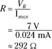

FIGURE 9-10: Be sure to insert a resistor in series with an LED to limit current to the LED.
Chances are you won’t find a resistor with the exact value you calculated, so choose a standard resistor with a higher value (such as 330 Ω or 390 Ω) to limit the current a bit more. If you choose a lower value (such as 270 Ω), the current will exceed the maximum current rating.
Turning on an LED
The circuit in Figure 9-11 is designed to demonstrate the on/off operation of an LED, and how increasing current strengthens the light emitted by the diode.
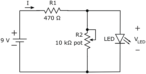
FIGURE 9-11: Use this circuit to turn an LED on and off, and to vary the intensity of the light.
Here’s what you need to build this circuit:
- One 9-volt battery and battery clip
- One 470 Ω 1/4 W (minimum) resistor (yellow-violet-brown)
- One 10 kΩ potentiometer with attached lead wires
- One red, yellow, or green LED (any size)
- At least one jumper wire
- One solderless breadboard
You can witness the LED turning on when the voltage across it reaches its forward voltage by using a multimeter. Here’s how you do it:
Zero the 10 kΩ pot.
Set your multimeter to ohms and place its leads across the potentiometer. Make sure you tie two of the leads together when you do this. Turn the pot knob all the way to one end or the other until you get a reading of 0 Ω (or just about 0 Ω).
Build the circuit, using Figure 9-12 as your guide.
Keep the same two pot leads together so that the pot is providing 0 ohms of resistance to the circuit. Make sure you orient the LED properly, with the cathode (negative side) connected to the negative battery terminal. (Remember that the cathode has a shorter lead and a larger plate inside the plastic housing.)
Set your multimeter to DC volts with a range of 10 V and place the leads across the LED (red lead at anode; black lead at cathode).
Is the LED lit? What voltage reading do you get? The LED voltage should be just a few millivolts, which is not enough to turn on the diode.
Dial the pot up slowly, keeping your eye on the LED. When the LED turns on, stop dialing the pot.
Observe the reading on the multimeter. Is the LED voltage close to 2 V?
Continue to dial the pot up as you watch the LED.
What is happening to the light? (It should be glowing brighter.)
Dial the pot all the way up to 10 kΩ and observe the intensity of the LED. Note the voltage reading on your multimeter.
Did the LED voltage change much as the light intensity increased?

FIGURE 9-12: By turning the pot’s knob, you vary the voltage across the LED. When the LED voltage exceeds about 2 V, the LED turns on.
To understand why the LED was off when the pot was set to 0 Ω and then turned on as you increased the pot resistance, consider the circuit if you remove the LED. The circuit is a voltage divider (described in Chapter 6), and the voltage across the pot (resistor R2) — which is the same as the LED voltage — is given by a ratio of resistance times the supply voltage:

If the resistance of the potentiometer is 0 Ω, the voltage across the LED is 0 V. As you increase R2 (that is, the resistance of the pot), the voltage across the LED increases. When R2 reaches a certain point, the voltage across the LED rises enough to turn on the LED. VLED climbs to about 2.0 V when R2 rises to about 134 Ω. (Plug in 134 for R2 in the preceding equation and see for yourself!)
Of course, your particular LED may turn on at a slightly different voltage, say in the range of 1.7 V to 2.2 V. If you measure the resistance of the pot (after removing it from the circuit) at the point at which your LED turns on, you may see a somewhat lower or higher resistance than 134 Ω.
You can also observe the current flowing through the LED by following these steps:
- Break the circuit between the cathode (negative side) of the LED and the negative battery terminal.
Set your multimeter to DC amps and insert it in series where you broke the circuit.
Make sure the red lead of your multimeter is connected to the cathode of the LED and the black lead of your multimeter is connected to the negative battery terminal so that you are measuring positive current flow.
Start with the pot turned all the way down to 0 Ω. As you dial the pot up, observe the current reading.
Note the reading when the LED first turns on. Then continue to dial the pot up and observe the current readings. You should see the current increase to over 14 mA as the light intensifies.
If you have two multimeters, try measuring the voltage across the LED with one multimeter (set to DC volts) and the current flowing through the LED with the other multimeter (set to DC amps) simultaneously. You should notice that the LED turns on when its voltage approaches 2.0 V, with just a tiny current passing through it at this point. As you increase the current through the LED, the light brightens but the voltage across it remains fairly steady.
Other uses of diodes
Among the many other uses of diodes in electronic circuits are the following:
- Overvoltage protection: Diodes placed in parallel with a piece of sensitive electronic equipment protect the equipment from large voltage spikes. The diode is placed backward so that it’s normally reverse-biased, acting like an open circuit and not playing any part in the normal operation of the circuit. However, under abnormal circuit conditions, if a large voltage spike occurs, the diode becomes forward-biased — which limits the voltage across the sensitive component and shunts excess current to ground to prevent harm to the component. (The diode may not be so lucky.)
- Construction of logic gates: Diodes are the building blocks of specialized circuits known as logic circuits, which process signals consisting solely of two voltage levels that are used to represent binary information (such as on/off, high/low, or 1/0) in digital systems. I discuss logic a bit more in Chapter 11.
- Current steering: Diodes are sometimes used in uninterruptible power supplies (UPSs) to prevent current from being drawn out of a backup battery under normal circumstances, while allowing current to be drawn from the battery during a power outage.