
Chapter 6
Obeying Ohm’s Law
IN THIS CHAPTER
![]() Understanding how current, voltage, and resistance are governed by Ohm’s Law
Understanding how current, voltage, and resistance are governed by Ohm’s Law
![]() Practicing Ohm’s Law by analyzing circuits
Practicing Ohm’s Law by analyzing circuits
![]() Using power as your guide in choosing circuit components
Using power as your guide in choosing circuit components
An intimate relationship exists between voltage (the electrical force that pushes electrons) and current in components that have resistance. That relationship is summed up nicely in a simple equation with an authoritative name: Ohm’s Law. In this chapter, you put Ohm’s Law to work to find out what’s going on in some basic circuits. Then you get a look at the role of Ohm’s Law and related power calculations in the design of electronic circuits.
Defining Ohm’s Law
One of the most important concepts to understand in electronics is the relationship between voltage, current, and resistance in a circuit, summarized in a simple equation known as Ohm’s Law. When you understand this equation thoroughly, you'll be well on your way to analyzing circuits that other people have designed, as well as successfully designing your own circuits. Before diving into Ohm’s Law, it may help to take a quick look at the ebbs and flows of current.
Driving current through a resistance
If you place a voltage source across an electronic component that has measurable resistance (such as a light bulb or a resistor), the force of the voltage will push electrons through the component. The movement of gobs of electrons is what constitutes electric current. By applying a greater voltage, you exert a stronger force on the electrons, which creates a stronger flow of electrons — a larger current — through the resistance. The stronger the force (voltage V), the stronger the flow of electrons (current I).
This is analogous to water flowing through a pipe of a certain diameter. If you exert a certain water pressure on the water in the pipe, the current will flow at a certain rate. If you increase the water pressure, the current will flow faster through that same pipe, and if you decrease the water pressure, the current will flow slower through the pipe.
It’s constantly proportional!
The relationship between voltage (V) and current (I) in a component with resistance (R) was discovered in the early 1800s by Georg Ohm (does his name sound familiar?). He figured out that for components with a fixed resistance, voltage and current vary in the same way: Double the voltage, and the current is doubled; halve the voltage, and the current is halved. He summed up this relationship quite nicely in the simple mathematical equation that bears his name: Ohm’s Law.
 Ohm’s Law states that voltage equals current multiplied by resistance, or
What this really means is that the voltage (V), measured across a component with a fixed resistance, is equal to the current (I) flowing through the component multiplied by the value of the resistance (R).
For example, in the simple circuit in Figure 6-1, a 9-volt battery applied across a 1 kΩ resistor produces a current of 9 mA (which is 0.009 A) through the circuit:
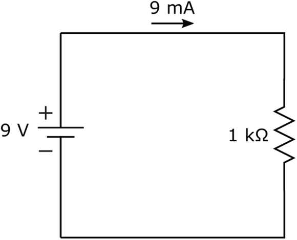
FIGURE 6-1: A voltage of 9 V applied to a resistor of 1 kΩ produces a current of 9 mA.
Ohm’s Law is so important in electronics that you’d be wise to repeat it over and over again, like a mantra, until you’ve mastered it! To help you remember, think of Ohm’s Law as a Very Important Rule.
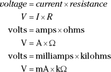
 When using Ohm’s Law, watch your units of measurement carefully. Make sure that you convert any kilos and millis before you get out your calculator. If you think of Ohm’s Law as
 ![]() , you’ll be okay. And if you’re brave, you can also use
, you’ll be okay. And if you’re brave, you can also use ![]() , which works just as well (because the millis cancel out the kilos).
, which works just as well (because the millis cancel out the kilos).
 But if you aren't careful and you mix units, you may be in for a shock! For instance, a lamp with a resistance of 100 Ω passes a current of 50 mA. If you forget to convert milliamps to amps, you’ll multiply 100 by 50 to get 5,000 V as the voltage across the lamp! Ouch! The correct way to perform the calculation is to convert 50 mA to 0.05 A, and then multiply by 100 Ω, to get 5 V. Much better!
Ohm’s Law is so important (did I say that already?) that I’ve created the following list to help you remember how to use it:
There’s a reason Georg Ohm has his name associated with resistance values as well as the law. The definition of an ohm, or unit of resistance, came from Georg Ohm’s work. The ohm is defined as the resistance between two points on a conductor when one volt, applied across those points, produces one amp of current through the conductor. I just thought you might like to know that. (Good that Georg’s last name wasn’t Wojciehowicz!)
One law, three equations
Remember your high-school algebra? Remember how you can rearrange the terms of an equation containing variables (such as the familiar x and y) to solve for one variable, as long as you know the values of the other variables? Well, the same rules apply to Ohm’s Law. You can rearrange its terms to create two more equations, for a total of three equations from that one law!
These three equations all say the same thing but in different ways. You can use them to calculate one quantity when you know the other two. Which one you use at any given time depends on what you’re trying to do. For example:
- To calculate an unknown voltage, multiply the current times the resistance (
 ). For instance, if you have a 2 mA current running through a 2 kΩ resistor, the voltage across the resistor is
  (or
(or  )
)  .
. - To calculate an unknown current, take the voltage and divide it by the resistance (
 ). For example, if 9 V is applied across a 1 kΩ resistor, the current is
  .
. - To calculate an unknown resistance, take the voltage and divide it by the current (
 ). For instance, if you have 3.5 V across an unknown resistor with 10 mA of current running through it, the resistance is
  .
.
Using Ohm’s Law to Analyze Circuits
When you have a good handle on Ohm’s Law, you’ll be ready to put it into practice. Ohm’s Law is like a master key, unlocking the secrets to electronic circuits. Use it to understand circuit behavior and to track down problems within a circuit (for instance, why the light isn’t shining, the buzzer isn’t buzzing, or the resistor isn’t resisting because it melted). You can also use it to design circuits and choose the right parts for use in your circuits. I get to these topics in a later section of this chapter. In this section, I discuss how to apply Ohm’s Law to analyze circuits.
Calculating current through a component
In the simple circuit you saw in Figure 6-1, a 9-volt battery is applied across a 1 kΩ resistor. You calculate the current through the resistor as follows:
If you add a 220 Ω resistor in series with the 1 kΩ, as shown in Figure 6-2, you’re restricting the current even more.
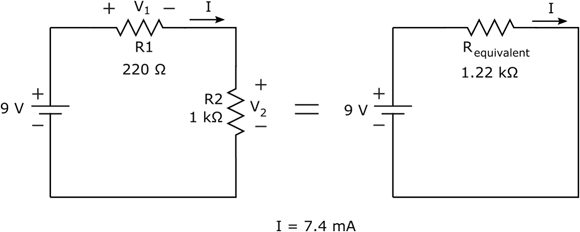
FIGURE 6-2: To calculate the current through this circuit, determine the equivalent resistance and apply Ohm’s Law.
To calculate the current flowing through the circuit, you need to determine the total resistance that the 9-volt battery is facing in the circuit. Because the resistors are in series, the resistances add up, for a total equivalent resistance of 1.22 kΩ. You use this equivalent resistance to calculate the new current, as follows:
By adding the extra resistor, you’ve reduced the current in your circuit from 9 mA to 7.4 mA.
That double squiggle symbol (≈) in the equation just given means “is approximately equal to,” and I used that because I rounded off the current to the nearest tenth of a milliamp. It’s usually okay to round off the tinier parts of values in electronics — unless you’re working on the electronics that control a subatomic particle smasher or other high-precision industrial device.
Calculating voltage across a component
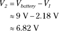
In the circuit that was shown in Figure 6-1, the voltage across the resistor is simply the voltage supplied by the battery: 9 V. That’s because the resistor is the only circuit element other than the battery. Adding a second resistor in series (refer to Figure 6-2) changes the voltage picture. Now some of the battery voltage is dropped across the 220 Ω resistor (R1), and the rest of the battery voltage is dropped across the 1 kΩ resistor (R2). I labeled these voltages V1 and V2, respectively.
To figure out how much voltage is dropped across each resistor, you use Ohm’s Law for each individual resistor. You know the value of each resistor, and you now know the current flowing through each resistor. Remember that current (I) is the battery voltage (9 V) divided by the total resistance (R1 + R2, or 1.22 kΩ), or approximately 7.4 mA. Now you can apply Ohm’s Law to each resistor to calculate its voltage drop:

Note that if you add the voltage drops across the two resistors, you get 9 volts, which is the total voltage supplied by the battery. That isn't a coincidence; the battery is supplying voltage to the two resistors in the circuit, and the supply voltage is divided between the resistors proportionally, according to the values of the resistors. This type of circuit is known as a voltage divider.
 There’s a quicker way to calculate either of the “divided voltages” (V1 or V2) in Figure 6-2. You know that the current passing through the circuit can be expressed as
You also know that:
and
To calculate V1, for example, you can substitute the expression for I shown above, and you get
You can rearrange the terms, without changing the equation, to get
Similarly, the equation for V2 is
By plugging in the values of R1, R2, and Vbattery, you get ![]() and
and ![]() , just as calculated earlier.
, just as calculated earlier.
The following general equation is commonly used for the voltage across a resistor (R1) in a voltage divider circuit:
Many electronic systems use voltage dividers to bring down a supply voltage to a lower level, after which they feed that reduced voltage into the input of another part of the overall system that requires that lower voltage.
In Chapter 5, you see an example of a voltage divider that reduces a 9-volt supply to 5 volts using 15 kΩ and 12 kΩ resistors. You can use the voltage divider equation to calculate the output voltage, Vout, of that voltage divider circuit, which is shown in Figure 6-3, as follows:
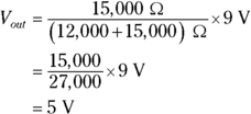
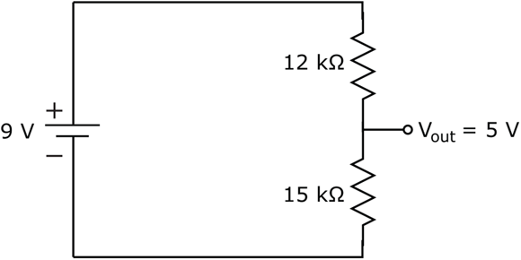
FIGURE 6-3: This voltage divider circuit reduces the 9-volt supply to 5 volts at Vout.
The circuit in Figure 6-3 divides a 9 V supply down to 5 V.
Calculating an unknown resistance
Say you have a large flashlight that you’re running off a 12-volt battery, and you measure a current of 1.3 A through the circuit. (I discuss how to measure current in Chapter 16.) You can calculate the resistance of the incandescent bulb by taking the voltage across the bulb (12 V) and dividing it by the current through the bulb (1.3 A). It’s a pretty quick number-crunch:
Seeing Is Believing: Ohm’s Law Really Works!
Ohm’s Law, which governs all resistive electronic components, is one of the most important principles in electronics. In this section, you can put Ohm’s Law to the test and take your first steps in circuit analysis.
Figure 6-4 shows a series circuit containing a 9 V battery, a 1 kΩ resistor (R1), and a 10 kΩ potentiometer, or variable resistor (R2). You are going to test Ohm’s Law for different values of resistance.

FIGURE 6-4: With a simple series circuit, you can witness Ohm’s Law in action.
To build this circuit, you need the following parts:
- One 9-volt battery
- One battery clip
- One 1 kΩ 1/4 W (minimum) resistor (brown-black-red stripes)
- One 10 kΩ potentiometer
- One solderless breadboard
Refer to Chapter 2 for information on buying these parts and Chapter 5 for details on resistors and potentiometers. You’ll need to attach wires to your potentiometer terminals so that you can connect the pot into your circuit. Refer to Chapter 15 for tips on attaching wires to pots and using a solderless breadboard. Because you will be measuring current, you may want to refer to Chapter 16 for details on how to use a multimeter.
Here are the steps to follow to build the circuit and test Ohm’s Law:
Connect the middle (wiper) lead and one outer (fixed) lead of the potentiometer.
When using a potentiometer (pot) as a two-terminal variable resistor, it's common practice to connect the wiper and one fixed lead together. This way, R2 is the resistance from the combined leads to the other outer (fixed) lead. By dialing the pot, you can vary the resistance of R2 between 0 (zero) Ω and 10 kΩ. For now, simply twist together the ends of the wires coming off the pot terminals.
Zero the pot.
With your multimeter set on ohms, measure the resistance of the pot from the wiper lead to the fixed lead that is not connected to the wiper. Then, dial the pot all the way in one direction or the other until your multimeter reads 0 Ω. This value is the pot resistance you will start with in your circuit.
Build the circuit using Figure 6-5 as your guide.
Note that it doesn’t matter which way you orient the 1 kΩ resistor or the pot (as long as you keep the same two pot leads together as you did when you measured the pot resistance). You can untwist the pot leads and insert them into neighboring holes on the breadboard.
Measure the current flowing through the circuit.
To measure current, you need to break the circuit and insert your multimeter in series with whatever you’re measuring current through. In a series circuit, the current flowing through each component is the same, so you can measure the current anywhere you want in the circuit. For this example, I tell you how to insert your multimeter between the resistor and the pot.
Before you insert your multimeter into the circuit, switch your multimeter to measure DC current in milliamps (a range of 20 mA is fine). Then, move the resistor lead that is connected to the pot to another column in your breadboard (or just leave the disconnected lead hanging). Now you’ve broken the circuit.
Connect the positive multimeter lead to the open side of the 1 kΩ resistor and the negative multimeter lead to the open side of the pot. Note the current reading.
Is this the reading you expect to get by applying Ohm’s Law to your circuit? Remember that because the pot is dialed all the way down to 0 Ω, the total resistance in your circuit — let’s call that Rtotal — is roughly 1 kΩ.
You should expect a current of roughly 9 mA because

 . Any discrepancies are due to variations in the supply voltage, the tolerance of the resistor, and the slight resistance of the multimeter.
Change the pot setting to 10 kΩ and observe the change in current.
With your multimeter still inserted in your circuit, dial the pot all the way to the other end so that its resistance is 10 kΩ. What current reading do you get? Is the actual current what you expected?
You should expect a current of roughly 0.82 mA because Rtotal is now 11 kΩ and
 .
.Change the pot to some intermediate setting and observe the current.
With your multimeter still inserted in your circuit, dial the potentiometer to some position in the middle of its range. Don’t worry about the exact value. What current do you measure now? Write it down.
Measure the resistance of the pot.
Remove the pot from the circuit without repositioning its dial. Remove your multimeter from the circuit, switch it to measure resistance in ohms, and measure the resistance of the potentiometer between the wiper (middle terminal) and the fixed terminal that is not connected to the wiper. If Ohm’s Law really works (which it should), you should find that the following equation is true:

where I is the current you measured in Step 6 and Rpot is the resistance you measured across the potentiometer.
You can experiment as much as you want, varying the pot and measuring the current and the pot resistance to verify that Ohm’s Law really does work.
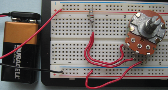
FIGURE 6-5: Your solderless breadboard makes the connections between components in this simple series circuit.
What Is Ohm’s Law Really Good For?
Ohm’s Law also comes in handy when you’re analyzing all kinds of circuits, whether simple or complex. You’ll use it in designing and altering electronic circuits, to make sure you get the right current and voltage to the right places in your circuit. You’ll use Ohm’s Law so much, it will become second nature to you.
Analyzing complex circuits
Ohm’s Law comes in handy when analyzing more complex circuits than the simple light bulb circuit discussed earlier. You often need to incorporate your knowledge of equivalent resistances to apply Ohm’s Law and figure out exactly where current is flowing and how voltages are being dropped throughout your circuit.
Look at the series-parallel circuit shown in Figure 6-6. Say you need to know exactly how much current is flowing through each resistor in the circuit.

FIGURE 6-6: Analyze complex circuits by applying Ohm’s Law and calculating equivalent resistances.
You can calculate the current running through each resistor, step by step, as follows:
Calculate the equivalent resistance of the circuit.
You can find this value by applying the rules for resistors in parallel and resistors in series (refer to Chapter 5 for details), like this:

Calculate the total current supplied by the battery.
Apply Ohm’s Law, using the battery voltage and the equivalent resistance of the circuit:

Calculate the voltage dropped across the parallel resistors.
You can do this calculation either of two ways, and you get pretty much the same result (the slight difference is due to rounding error):
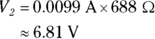
- Apply Ohm’s Law to the parallel resistors. You calculate the equivalent resistance of the two resistors in parallel, and then multiply that by the supply current. The equivalent resistance is 688 Ω, as shown in the first step. So the voltage is
- Apply Ohm’s Law to R1 (the 220 Ω resistor), and subtract its voltage from the supply voltage. The voltage, V1, across R1 is
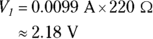
So the voltage, V2, across the parallel resistors is
- Apply Ohm’s Law to the parallel resistors. You calculate the equivalent resistance of the two resistors in parallel, and then multiply that by the supply current. The equivalent resistance is 688 Ω, as shown in the first step. So the voltage is
Finally, calculate the current through each parallel resistor.
To get that result, you apply Ohm’s Law to each resistor, using the voltage you just calculated (V2). Here’s what it looks like:
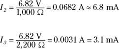
Note that the two branch currents, I2 and I3, add up to the total supply current, I1:
 . That’s a good thing (and a good way to check that you’ve performed your calculations correctly).
Designing and altering circuits
You can use Ohm’s Law to determine what components to use in a circuit design. For instance, you may have a series circuit consisting of a 9 V power supply, a resistor, and an LED, as shown in Figure 6-7.
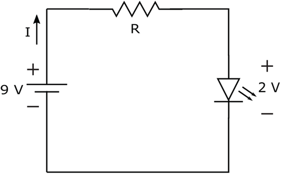
FIGURE 6-7: You can use Ohm’s Law to determine the minimum resistance you need to protect an LED.
As you see in Chapter 9, the voltage drop across an LED remains constant for a certain range of current passing through it, but if you try to pass too much current through the LED, it will burn out. For example, suppose your LED voltage is 2 V and the maximum current it can handle is 20 mA. What resistance should you put in series with the LED to limit the current so it never exceeds 20 mA?
To figure this out, first you have to calculate the voltage drop across the resistor when the LED is on. You already know that the supply voltage is 9 V and the LED eats up 2 V. The only other component in the circuit is the resistor, so you know that it will eat up the remaining supply voltage — all 7 V of it. If you want to limit the current to be no more than 20 mA, you need a resistor that is at least ![]() . Because it’s hard to find a 350 Ω resistor, suppose you choose a commonly available resistor that is close to, but higher in value than, 350 Ω, such as a 390 Ω resistor. The current will be
. Because it’s hard to find a 350 Ω resistor, suppose you choose a commonly available resistor that is close to, but higher in value than, 350 Ω, such as a 390 Ω resistor. The current will be ![]() , or about 18 mA. The LED may burn a little less brightly, but that’s okay.
, or about 18 mA. The LED may burn a little less brightly, but that’s okay.
Ohm’s Law also comes in handy when tweaking an existing circuit. Say your spouse is trying to sleep but you want to read, so you get out your big flashlight. The bulb in your flashlight has a resistance of 9 Ω and is powered by a 6 V battery, so you know that the current in the flashlight circuit is ![]() . Your spouse thinks the light is too bright, so to reduce the brightness (and save your marriage), you want to restrict the current flowing through the bulb a bit. You think that bringing it down to 0.45 A will do the trick, and you know that inserting a resistor in series between the battery and the bulb will restrict the current.
. Your spouse thinks the light is too bright, so to reduce the brightness (and save your marriage), you want to restrict the current flowing through the bulb a bit. You think that bringing it down to 0.45 A will do the trick, and you know that inserting a resistor in series between the battery and the bulb will restrict the current.
But what value of resistance do you need? You can use Ohm’s Law to figure out the resistance value as follows:
- Using the desired new current, calculate the desired voltage drop across the bulb:

Calculate the portion of the supply voltage you’d like to apply across the new resistor.
This voltage is the supply voltage less the voltage across the bulb:

- Calculate the resistor value needed to create that voltage drop given the desired new current:
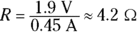
Choose a resistor value that is close to the calculated value, and make sure it can handle the power dissipation:
As you see in the next section, to calculate the power dissipated in an electronic component, you multiply the voltage dropped across the component by the current passing through it. So the power that your 4.2 Ω resistor needs to be able to handle is

Result: Because you won’t find a 4.2 Ω resistor, you can use a 4.7 Ω 1 W resistor to reduce the brightness of the light. Your spouse will sleep soundly; let’s hope the snoring won’t interfere with your reading!
The Power of Joule’s Law
Another scientist hard at work in the early 1800s was the energetic James Prescott Joule. Joule is responsible for coming up with the equation that gives you power values; it’s known as Joule’s Law:
This equation states that the power (in watts) equals the voltage (in volts) across a component times the current (in amps) passing through that component. The nice thing about this equation is that it applies to every electronic component, whether it’s a resistor, a light bulb, a capacitor, or something else. It tells you the rate at which electrical energy is consumed by the component — what that power is.
Using Joule’s Law to choose components
You’ve already seen how to use Joule’s Law to ensure that a resistor is big enough to resist a meltdown in a circuit, but you should know that this equation comes in handy also when you’re selecting other electronic parts.
Lamps, diodes (discussed in Chapter 9), and other components also come with maximum power ratings. If you expect them to perform at power levels higher than their ratings, you’re going to be disappointed when too much power makes them pop and fizzle. When you select the part, you should consider the maximum possible power the part will need to handle in the circuit. You do this by determining the maximum current you’ll be passing through the part and the voltage across the part, and then multiplying those quantities together. Then you choose a part with a power rating that exceeds that estimated maximum power.
Joule and Ohm: perfect together
You can get creative and combine Joule’s Law and Ohm’s Law to derive more useful equations to help you calculate power for resistive components in circuits. For instance, if you substitute I × R for V in Joule’s Law, you get:
That gives you a way to calculate power if you know the current and resistance but not the voltage. Similarly, you can substitute V/R for I in Joule’s Law to get
Using that formula, you can calculate power if you know the voltage and the resistance but not the current.
Joule’s Law and Ohm’s Law are used in combination so often that Georg Ohm sometimes gets the credit for both laws!