Chapter 6. How Traditional Radio Works
Radio waves, prediction and discovery. Electric and magnetic fields, electromagnetic waves. Waves in free space and in waveguides. Ionosphere effect. Wavelength, speed, and frequency. Dipole antenna. Polarization of antenna. Transmitting radio signals. Receiving radio signals. Rectification of waves. Modulation of carrier wave. Amplitude modulation. Microphone as a transducer. Vacuum tubes in early radio. Sidebands in modulated carrier. Suppressed carrier and single-sideband systems. Radio in 1920s and 1930s. Interference between stations. Frequency modulation and Edwin Armstrong. Early receiver block diagrams. Detector or demodulator. Sensitivity and selectivity. TRF receivers. The superhet receiver block. Mixer and intermediate frequency. Automatic gain control (AGC). Cause of fluctuating signal strength. Automatic frequency control (AFC) for FM receivers. Stereo radio principles. Use of a sub-carrier. Pilot tone. Suppressed carrier operation. Block diagrams for stereo radio transmitter (Tx) and receiver (Rx). Phase-sensitive demodulator. Replacement of FM by digital radio. Internet radio
Radio Waves
We use the phrase
radio waves to mean electromagnetic waves that are transmitted across space (not just through air), as distinct from waves conducted along wires or in tubes (
waveguides). The existence of radio waves was predicted by the mathematician Clerk Maxwell in 1864 and later discovered experimentally by Heinrich Hertz in 1887, but no use was made of the waves until early in the twentieth century when Marconi (along with Popov, Tesla, and several others) used them for communications. They have come a long way in a period of about 100 years.
Note
Note
This is a very familiar pattern: a mathematician discovers relations between physical quantities and years later we find that we can make use of these relations. Nations that do not nurture their mathematicians (on the grounds that the work seems pointless), or pretend that ‘maffs' means just simple arithmetic, are doomed to be second rate.
We now know fairly well what happens. When we cause a voltage to exist between any two points in space, the
space itself is distorted, and we refer to the effect as an
electric field. A varying voltage causes a variable distortion which appears to us as magnetism; we say that a
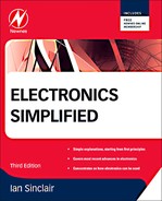
magnetic field exists, meaning that this piece of space causes magnetic effects. This is a changing magnetic field, however, and its effect is to generate another voltage some distance away, which in turn causes a magnetic field and yet another voltage field, and so on. The unique feature of the waves is that the direction of oscillation of the magnetic wave is at right angles to the direction of oscillation of the electric waves (Figure 6.1).
 |
| Figure 6.1 Illustration of how electric and magnetic waves combine to form an electromagnetic wave |
These alternating fields are waves of both electricity and magnetism, called
electromagnetic waves. They travel away from the point where they were generated at a speed of around 300,000,000 meters per second (often written as 3
×
10
8m
s
−1), which is also the speed that has been measured for light, a strong hint that light is itself an electromagnetic wave. No air or any other material is needed to transmit these electromagnetic waves, though they can pass through insulating materials and they can also be conducted along metals and other conducting materials and through tubes called
waveguides. Electromagnetic waves travel in straight lines, they can be reflected, refracted, and focused, and they can also be polarized (see later); all effects that are familiar from our knowledge of how light behaves.
In the early days of radio, all academic experts believed that long-distance communication by electromagnetic waves was impossible because of the curvature of the Earth. They would have known better if they had followed the work of Oliver Heaviside, who worked out that the effect of the radiation from the Sun would be to split atoms of gas in the upper atmosphere (the
ionosphere) and provide a conducting layer that would reflect waves. Heaviside, however, was regarded as an eccentric engineer and was scorned by academics (does that sound familiar?), and much of his work was not published until after his death. Marconi and others disregarded the academics and pressed on with radio contacts over greater and greater distances, culminating in the transatlantic transmission in 1901. Academics then had to rediscover all that Heaviside had done and pretend that they had discovered it themselves. We will come back to the effects of the ionosphere later.
All electromagnetic waves travel at the same speed in space, and the speed is almost the same in air, though slower in denser materials. In addition, these waves have a measurable
wavelength, meaning the distance from the peak of one wave to the peak of the next. As for water waves and sound waves, the speed, frequency, and wavelength are related by the equations:
 with
f meaning frequency in hertz (Hz),
v speed in meters per second (m
s
−1), and
λ wavelength in meters (m). For example, if you generate a signal at 1
MHz, then its wavelength in space is 300,000,000 divided by 1,000,000, which is 300
m. A wave at 100
MHz, such as we use for FM radio, has a wavelength of 300,000,000/100,000,000 which is 3
m. Table 6.1 shows a few examples of frequencies and wavelengths.
with
f meaning frequency in hertz (Hz),
v speed in meters per second (m
s
−1), and
λ wavelength in meters (m). For example, if you generate a signal at 1
MHz, then its wavelength in space is 300,000,000 divided by 1,000,000, which is 300
m. A wave at 100
MHz, such as we use for FM radio, has a wavelength of 300,000,000/100,000,000 which is 3
m. Table 6.1 shows a few examples of frequencies and wavelengths.
Definition
Note
Definition
Radio waves are electromagnetic waves in space (which includes air) traveling at around 300 million meters per second. The frequency of a wave is the number of oscillations per second, and this causes a wave to have a wavelength which is found from speed/frequency.
Note
Electromagnetic waves travel at a lower speed in insulating materials, and also when they travel along wires or in metal tubes. The relationship between wavelength, frequency, and speeds is the same, but waves traveling in insulators or along wires have a shorter wavelength than the same waves in space because of the lower speed.
| Frequency | Wavelength |
|---|---|
| 100 kHz | 3 km |
| 1 MHz | 300 m |
| 5 MHz | 60 m |
| 10 MHz | 30 m |
| 20 MHz | 15 m |
| 50 MHz | 6 m |
| 100 MHz | 3 m |
| 400 MHz | 75 cm |
| 1 GHz | 30 cm |
| 10 GHz | 3 cm |
It is not difficult to generate and launch waves in the frequency range that we use for radio. Anything that produces an alternating voltage will generate the signals, and any piece of wire will allow them to radiate into space. We find, however, that a launching wire, which we call an antenna (aerial in the UK), works best when its length is an even fraction (such as ½ or ¼) of the wavelength of the wave, or several wavelengths long. Lengths of half a wavelength or quarter of a wavelength are particularly useful, and a very efficient system, called a
dipole, has been used for many years. These tuned aerials are not so efficient (and are difficult to construct) for the very long wavelengths, and they really come into their own for wavelengths of a few meters or less. Though we still make considerable use of the very long wavelengths, most of the communications equipment (FM radio, television, mobile phones) that we use nowadays depends on using the short wavelengths. The limitations of short wavelengths for long-distance communications are overcome by using satellites, so allowing a straight-line path for signals to and from the satellite.
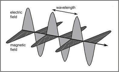
A dipole antenna (Figure 6.2) for a wavelength that you want to use consists of two rod sections, each one-quarter of a wavelength long. If you imagine the inside portions connected to a signal, the voltage on the antenna rods will be in the pattern of a wave, and when the voltage is almost zero at the center it will be a maximum at the ends. This is the type of antenna that is very familiar to us and is used for television and FM radio reception, with the rods cut to the correct quarter-wavelength size for the nearest set of transmitters. The dipole is most efficient for the wave that is exactly of the size, but this is not too critical, particularly if the rods of the dipole are thick. The points where the (
feeder) cable is attached correspond to the points of maximum signal current so that the antenna behaves like a low resistance as far as signals of the tuned frequency are concerned.
 |
| Figure 6.2 Dipole antenna principles. The dashed lines represent the half-wave of signal at the antenna, ensuring the maximum signal current to the feeder line of a receiver (or from the feeder of a transmitter) |
Dipoles are also polarized. Polarization, as far as radio antennae are concerned, means the direction of the
electric field of the wave, and this is often fixed by the design of the transmitting antenna as either vertical or horizontal. If the transmitter uses a vertical dipole, the signal will be vertically polarized, and the receiver antenna should also be vertically polarized. If the transmitter uses horizontal polarization, the receiver antenna should also be horizontally polarized. Different polarization directions are used to reduce interference between transmitters that use the same (or close to the same) frequency, and in some cases because one direction of polarization provides better reception conditions in difficult terrain than the other.
Note
Summary
Note
Where the length of a dipole might be excessive, or if a dipole would be inconvenient (as for a car phone, for example), we can use the upper half of a dipole, often referred to as a
monopole or
whip antenna. The length of a dipole can be reduced by wrapping a wire dipole around a magnetic material, and this applies also to a monopole, as used for mobile phones.
Summary
Radio waves all travel at the same speed in space, and have measurable wavelength and frequency values. These quantities are related, and speed
=
wavelength
×
frequency. Radio waves are of the type called electromagnetic waves, differing in frequency, and including light, infrared and ultraviolet, X-rays, gamma-rays, and many others that were discovered but not originally thought to be electromagnetic. A radio wave is most efficiently radiated from a metal antenna whose length is a suitable fraction of a wavelength, such as half-wave, and reception of radio waves is best when the receiving antenna is also a suitable fraction of a wavelength. For low frequencies with wavelengths of several kilometers, half-wave antennae are impossible, and it is fortunate that half-wave antennae are most needed for waves whose wavelengths are less than a couple of meters. Dipole antennae are polarized, and their direction of polarization should match that of the transmitter.
Transmission and Reception
Early radio transmitters used electrical sparks to generate signals, which were a mixture of many frequencies, mainly in the very high-frequency (VHF)/ultrahigh-frequency (UHF) range, and at a short range these were seen to cause sparks to appear across the two sections of a receiving antenna. More sensitive ways of detecting the received signal soon followed, and a device called a coherer, consisting of metal filings in a glass tube, was used extensively, along with headphones, in the early days of radio as a way of detecting signals that were too feeble to make a spark.
For some time, large land-based transmitters used mechanical generators, alternators, working at about 20
kHz, and with huge long-wire antennae, so that their signals could span the Atlantic. These, and spark generators, were used until radio vacuum tubes were invented around 1906, though spark transmitters were still in use when the Titanic sank in 1912. An interesting point is that her distress signals were picked up in New York by a Marconi radio operator called David Sarnoff (who later founded the Radio Corporation of America when the US government threatened Marconi's with the equivalent of nationalization).
Reception of radio waves is simple enough: make a dipole or a single-wire antenna, and detect the small currents at the center terminals. Detection is a snag, though. At the start of the twentieth century, there was nothing that could amplify a signal at 20
kHz, and devices such as earphones could not respond to such higher frequencies or the much higher frequencies that were generated from sparks. The only way that the presence of the wave could be detected was by what we now call
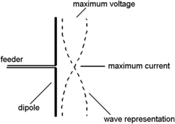
rectification, using some device that would allow the current to flow only one way and then detect the direct current (DC). The coherer with its metal filings was the first attempt to make such a device, but later it was discovered that crystals of the mineral galena (chemically, lead sulfide) could be used. The crystal was placed in a metal holder connected to earphones, and an antenna was connected to a fine wire, called a
cat's whisker, jabbed against the crystal (Figure 6.3).
 |
| Figure 6.3 A crystal set. This vintage radio diagram shows the use of a crystal and a fine wire (cat's whisker) to rectify radio waves into the audio signal. The resulting signals could be heard in earphones. A handle allowed the whisker to be moved on the crystal surface |
When a radio wave hit the antenna, the alternating current flowed only one way through the coherer or the crystal, and the headphones gave a feeble click, which sounded reasonably loud if you happened to be wearing the headphones. If the radio waves had been switched on and off again quickly, the sound in the headphones was a short double-click; if the wave was sustained for longer the gap between clicks was longer. By switching the transmitter on and off using a Morse key, a skilled listener could read the short (dot) and long (dash) intervals between clicks and write down the Morse code message that was being transmitted. This was the basis of radio as we used it right into the 1920s.
Summary
Summary
Anything that can generate electrical oscillations can form the basis of a transmitter, and early designs used sparks, generating a huge mixture of wavelengths. Later designs used mechanical generators for low-frequency waves that required huge antennae. Communication was carried out by using Morse code, switching the signals on and off in the familiar dot and dash patterns.
Neither coherer nor crystal was really satisfactory. The coherer had to be tapped regularly to settle the filings into place, and the cat's whisker had to be moved over the crystal surface to find a ‘sweet spot', a place where the action was most effective. This movement of the cat's whisker often had to be repeated, usually just as you particularly wanted to get the important part of a message.
Modulation
Morse code served radio well and is still useful for emergency purposes because it requires the absolute minimum of equipment and it is the most efficient use of radio; even a low-power long-wave transmitter can have a very long range using Morse. It is not exactly useful for entertainment purposes, however, or for long-distance telephone calls, and though a method of carrying sound signals over radio waves had been demonstrated early on (on Christmas day in 1906), it took a long time to make this a commercial proposition (in 1920, in fact). The use of radio waves to carry the information of sound waves requires what we call
modulation, and in the early days of radio this was always the type we call
amplitude modulation (
AM).
Note
Note
It's an amusing thought that tapping out a message in Morse is still faster than trying to type a text message on a mobile phone, and it uses only a tiny fraction of the bandwidth.
To start with, we have to change the sounds, whether speech or music, into electrical waves, using a type of transducer called a
microphone. Microphones were, thanks to the use of telephones, reasonably familiar devices in 1906 (in the USA at least), so that the only obstacle to broadcasting in these early days was knowing how to make a radio wave of 100
kHz or more carry a wave, the audio signal, of a much lower frequency, about 300
Hz. The simplest answer is to make the amplitude of the radio wave rise and fall in sympathy with the lower (audio) frequency (Figure 6.4). This is what we mean by
amplitude modulation: the amplitude of the carrier wave is controlled by the amplitude of the audio signal.
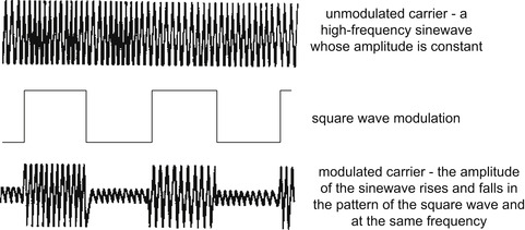 |
| Figure 6.4 Amplitude modulation. The signal, shown here as a square wave, alters the shape of the carrier outline so that the resulting outline (the envelope) has the same shape and frequency as the modulating wave |
Amplitude modulation had been possible even in the early days of spark transmitters, but only with difficulty and using primitive equipment. The use of radio
vacuum tubes, or just ‘tubes', in the USA, made efficient modulation possible, because the vacuum tube (called a valve in the UK) allows a large current to be controlled by a small voltage. In addition, another tube can be used as an oscillator, generating the radio waves and replacing the mechanical or spark type of generators. The first radio station intended for entertainment started operation in November 1920 at Pittsburg, Pennsylvania. The usual way of modulating was to control the DC supply to the output tube of the transmitter, using another tube, and applying the amplified audio signal as the input of this tube.
When a radio wave is modulated in this way, it is no longer a simple sinewave. If we could graph the waveform we would find the type of shape illustrated in Figure 6.4, but there is another effect that is shown only when we graph the signal amplitude against
frequency rather than against time.
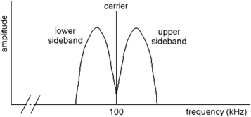
Suppose, for example, that we modulate a 100
kHz radio wave with a 10
kHz sinewave signal. Analyzing the frequencies that are present shows that three main waves now exist. One is at 100
kHz and is the
carrier wave, the wave that is generated by an oscillator. There is also a wave with a frequency of 90
kHz, called the
lower sideband, and one with a frequency of 110
kHz, called the
upper sideband. These sidebands appear only when the carrier is being modulated, and their amplitude is always less than that of the carrier (Figure 6.5). In general, if the carrier frequency is
F and the signal frequency is
f, the sidebands are at
F−
f and
F+
f, so that the total bandwidth of the transmitted wave is from
F−
f to
F+
f, making a bandwidth of 2
f.
 |
| Figure 6.5 Sidebands. A carrier can be represented as a vertical line on a graph of amplitude plotted against frequency. When this carrier is modulated by a sinewave, two more frequencies are present, the upper and lower sidebands. The transmitter must provide the extra power represented by these additional frequencies |
If we modulate the carrier with a signal that consists of a mixture of frequencies up to 10
kHz in bandwidth, the sidebands will show a pattern such as appears in Figure 6.6, showing a spread of sideband frequencies rather than just two single frequencies. In each sideband, the frequencies closest to the carrier frequencies are due to the lower frequencies of the modulating signal, and the frequencies furthest from the carrier frequency are due to the higher frequencies of the modulating signal.
 |
| Figure 6.6 Audio signal sidebands. When the carrier is modulated by a range of frequencies, as it would be for an audio signal, the sidebands cover a range of frequencies that is equal to the audio bandwidth. Both upper and lower sidebands contain the same signal information |
All we need to carry the information is one of these sidebands, so that both the carrier frequency and the other sideband are redundant. There are ways that can be used of eliminating the carrier (
suppressed carrier transmission) and one sideband (
single-sideband transmission) from the transmitted signal, but for entertainment purposes the additional complications at the receiver make these methods undesirable, though both stereo radio and color television make some use of these methods for additional signals (using
sub-carriers; see later). Digital radio is quite another matter, as discussed later.
Summary
Summary
Modulating a radio carrier wave always causes sidebands to appear. For amplitude modulation, the difference between a sideband frequency and the carrier frequency is equal to the modulating frequency. A modulated wave therefore requires a greater bandwidth than an unmodulated wave, and its efficiency is low, because the carrier and one sideband contribute nothing: all of the information is contained in each sideband (so that either sideband can be used to extract the signal at a receiver).
Reception
At the receiving end, vacuum tubes were still a far-off dream for the few people in 1920, mainly amateur enthusiasts, who could get hold of crystals and headphones and rig up an antenna. Some 1000 listeners probably heard the 1920 US presidential election results in this way, and in later years this number multiplied rapidly. Even in controlled and restricted Britain listeners experimented, trying to hear the trial transmissions from the Marconi workshop in Writtle (Essex) and even from continental broadcasts when conditions and geographical position suited. In 1922, a private company, the British Broadcasting Company (BBC), was formed and it set up nine transmitters, each with a distinctive call sign of digits and letters. Table 6.2 shows these nine with opening dates and frequency allocation.
By the 1930s, radio as we know it was a reality. The BBC had been nationalized so that the government could control it and tax it, but in the USA broadcasting remained free in every sense and consequently the USA remained at the front of technical progress. Small tubes became available and were used in receivers, and by the 1930s loudspeakers were normally used in place of headphones so that the whole family could listen in. Amplitude modulation was used for transmissions with frequencies in the medium waveband of about 530
kHz to 1.3
MHz, and the receivers developed from the simple one-tube pattern to multitube types, some of the expensive models featuring an added electronic record-player to make a radiogram. By the late 1930s a few lucky people in the London area could, if they could afford it, buy a combined radio and television receiver (though television was confined to a couple of hours in the evening, and a receiver cost as much as did a small house at that time).
A severe problem with the use of AM and the medium waveband was interference between stations. Medium-wave broadcasts can be picked up over quite long distances, up to 1000 miles (over 600
km), and where two stations used frequencies that were close, they set up an interference that could be heard as a whistle at a receiver tuned to either station. The whistle, in fact, is at the frequency that is the difference between the two transmitted frequencies. For example, if one station transmits at 600
kHz and another at 605
kHz, the whistle is heard at a frequency of 5
kHz. As new radio transmitters were introduced all over the world, it became quite impossible to share out frequencies on the medium waveband, and interference became the common experience for all listeners, particularly after dark when the reflecting layers in the ionosphere moved higher and reflected waves that originated from greater distances.
A way of getting around these problems had been devised by an inventor who, of all that ill-treated fraternity, was the least fortunate. Edwin Armstrong developed
frequency modulation (FM) to eliminate the effects of interference, both artificial and natural, and built a radio station (now a working museum) in the Catskill mountains just outside New York to prove the point. As the name suggests, the low-frequency audio signal is carried by altering the
frequency of the radio signal (Figure 6.7), with the amplitude kept constant. Since interference of all types only alters the amplitude of radio waves, FM can be virtually free from interference unless it is so severe as to reduce the radio wave amplitude to almost zero. FM is used universally today for high-quality broadcasts and for short-range local radio because if two FM transmitters are using almost the same frequency, a receiver will lock on to the stronger transmission, ignoring the other one and with no whistle effects. There is strong resistance to the proposal to turn off FM broadcasts all over Europe because of the poor coverage of digital radio (digital audio broadcasting or DAB) in so many parts of the UK. FM broadcasting in the UK did not start until 1955, though there were some commercial FM transmitters in the USA by 1941.
Summary
Summary
Medium-wave broadcasting became so popular that by the later 1930s there were too many transmitters to permit a reasonable bandwidth to be used by each, and the interference between transmitters that were on adjacent frequencies caused whistling noises in receivers. The solution was to use a different modulation system, FM, and to transmit FM signals using high-frequency carriers, typically in the 100
MHz region.
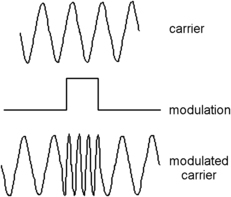 |
| Figure 6.7 Principle of frequency modulation. The amplitude of the carrier remains constant, and the signal alters the frequency of the carrier. The amount of alteration is called the deviation of the carrier. The bandwidth of sidebands created by this type of modulation is larger than that created by amplitude modulation |
Radio Block Diagrams
Early Receivers
Early radio receivers for AM signals consisted only of an antenna, a crystal, and headphones. This arrangement could be used close to a transmitter, and when a coil and capacitor were added it became possible to tune to more than one transmitter signal (assuming there was more than one transmitter within the very limited range of a crystal receiver). The crystal is the
detector or
demodulator that allows the low-frequency signal to be extracted from the radio wave, and the principles of AM now are still the same as they were then. When a modulated signal is passed through any device that allows only one-way current (a
demodulator), only half of the modulated wave will pass through. As Figure 6.8 shows, this makes the signal asymmetrical, and a small-value capacitor between this point and earth (together with the resistance of the earphones) will integrate the signal, ignoring the rise and fall of the radio frequency waves and following only the modulation signal.
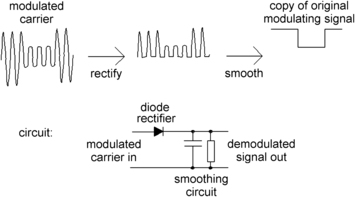 |
| Figure 6.8 Principles of amplitude demodulation (detection). The diode rectifier passes only one half of the modulated carrier, and filtering leaves only the outline which corresponds to the modulating signal |
All radio receivers have developed from this simple beginning, and the two aims of development have been to improve both
sensitivity and
selectivity. Sensitivity means the ability to pick up and use faint signals from remote or low-power transmitters. Selectivity means the ability to separate radio signals that are of closely adjacent frequencies. Both are important if you want to use a radio with a large choice of transmissions.
Sensitivity requires amplification, and selectivity requires tuning. Though this was well understood in the early days of radio, there were always problems. For example, if you amplify a radio wave too much there is a danger of
positive feedback (when the amplified signal can affect the input), causing the receiver to oscillate, and drowning out reception for all other receivers near it. If a receiver is too selective, the sound that you hear is unintelligible, lacking the higher frequencies. In the phrase that was used at the time, it is a ‘mellow bellow', the sort of noise you now hear from cruising cars.
By the start of the 1930s, a typical radio receiver followed a design called
TRF, meaning tuned radio frequency, for which the block diagram is shown in Figure 6.9. The feeble signal from the antenna is both amplified and tuned in one or more amplifying stages that used tubes. The tuning circuit used a coil and a variable capacitor (two sets of metal vanes separated by air and arranged so that they could mesh in and out). If more than one tuned circuit was used for greater selectivity, the tuning capacitors had to be ‘ganged', meaning that they could be moved in step with each other, using a single metal shaft to carry all the moving vanes of all the capacitors, and a single control. The sensitivity of these radios was often improved by a small amount of positive feedback of the radio signal, and the crystal that had been used in the early days was replaced by another tube, a
diode, that carried out the action of demodulation.
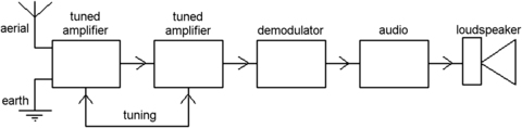 |
| Figure 6.9 A block diagram for a tuned radio-frequency (TRF) receiver, the first type of receiver that was constructed using vacuum tubes |
The action of the diode demodulator was the same as that of the older crystal, but with the advantage that tube diodes could be mass produced and were much more reliable because they did not rely on a contact between a wire and a crystal, all in open air. The output signal from the diode was still very feeble, more suited to earphones than to a loudspeaker, so that the natural path of development was to add another tube amplifier for the low-frequency audio signal, usually with a low-pass filter to get rid of the remains of the radio-frequency signal and so prevent it from being fed back to earlier stages.
These radios were a very considerable improvement, in both sensitivity and selectivity, on the old crystal sets, particularly when more than one stage of tuning was used, but as the medium waveband started to become crowded the old problems returned. Selectivity was still not enough, and attempts to increase sensitivity caused positive feedback and ‘howling'. This latter problem was caused by excessive feedback that caused a receiver to oscillate and transmit an interfering frequency for other receivers. Causing howling was looked on as highly antisocial, and some remedy had to be found. Attempts to make radios with three or more tuned circuits made the problem worse, because with three tuning capacitors on one shaft, there was always a path for positive feedback of waves from the output to the input.
Summary
Summary
The most primitive radio system following the crystal set was the TRF receiver. A set of tuned circuits along with amplifier stages was used to select and amplify the wanted frequency. This amplified signal was then demodulated and the audio signal further amplified to drive a loudspeaker. The disadvantage was that the tuned circuits had to be ganged, which made it impossible to isolate them from each other, so that positive feedback and oscillation were always a problem.
The Superhet
The solution to the problems of medium-wave radio lay in yet another earlier invention by Edwin Armstrong. This bore the full title of the
supersonic heterodyne receiver, abbreviated to ‘
superhet', and it is still the main type of circuit that we use for all reception of radio, television, and radar today. The principle is to eliminate as far as possible the amplification of the carrier frequency, so that variable tuning is used only at the start of the receiver block. The invention deliberately makes ingenious use of the ‘whistle' frequency that is generated when two radio frequencies are mixed together.
The principle, as it is used in medium-wave radios, is illustrated in Figure 6.10. A tuned circuit selects an incoming carrier, or a small range of carrier frequencies, from the antenna and this is used as the input to an amplifier. At the same time, another frequency is generated in an
oscillator circuit and applied to the same amplifier. In a conventional medium-wave receiver this generated frequency is not the same as the received frequency, it is exactly 550
kHz higher, and the tuning capacitor for the oscillator is ganged to the input tuning capacitor so that these frequencies stay exactly 550
kHz apart as the shaft of the capacitors is turned to change the tuning.
Note
Note
The block diagram shows actions that were often combined in older radios, so that, for example, the tuned amplifier, oscillator, and mixer actions were often carried out by one radio tube. Later, actions were separated and each action was carried out by a separate transistor. Later still, the whole set of actions could be carried out in a single integrated circuit (IC).
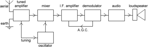 |
| Figure 6.10 A block diagram for a typical superhet receiver, showing the automatic gain control (AGC) connection |
The result is that the outputs from the first stage, called the
mixer, consist of four lots of radio signals. Suppose, for example, that the incoming radio wave is at 700
kHz and is amplitude modulated. The oscillator will be set to generate an unmodulated 1250
kHz radio wave, and the result is that the output of the mixer consists of waves of 700
kHz, 1250
kHz, 550
kHz, and 1950
kHz. These are the input signals plus the sum and difference of the frequencies. These sum and difference frequencies are modulated exactly like the input frequency.
Now the 550
kHz signal is easy to separate by a tuned filter, and it can be amplified. Any feedback of this signal to the input of the amplifier is not likely to cause much harm, because it is at a very different frequency from either the input wave or the generated wave. In addition, because this new frequency, called the
intermediate frequency (
IF), is fixed, it can be tuned by circuits that are fixed; there is no need to try to alter the tuning of these circuits when you tune from one station to another. As an extra precaution, metal boxes can be put over the IF tuned circuits to reduce any feedback even further. Adding more IF stages dramatically increases both selectivity (because there are more tuned circuits) and sensitivity (because there are more amplifier stages), so solving, for quite a long time, the problems of the crowded medium waves.
One feature that was used more and more, even in the early days, is
automatic gain control (AGC). The superhet can be a very sensitive receiver, and if it is sensitive enough to provide a usable output from the faint, faraway, transmitters, then the nearby ones are likely to overload it, causing severe distortion. In addition, because radio waves are reflected from shifting layers of charged particles in the sky (the ionosphere), the received signal usually fluctuates in strength unless it comes from a nearby transmitter. Figure 6.11 illustrates this, showing a wave that can reach a receiver by two paths, one of which is a reflected path.
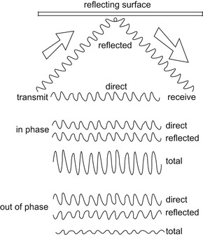 |
| Figure 6.11 Why automatic gain control (AGC) is needed. Unless a receiver is very close to the transmitter, a mixture of direct and reflected waves will be picked up, and the phase of the reflected waves will vary as the charged layers (ionosphere) move. This causes alternate reinforcement and reduction in total signal strength |
At any instant, these two waves can be in or out of phase. When they are perfectly in phase, they add so that the signal strength is increased compared to the strength of a single wave. When the waves are out of phase, the signal strength is reduced. Because the reflecting layers in the atmosphere are charged particles located a few hundred miles above the surface of the Earth and continually moving, the phase of the reflected signal is constantly changing, and so the received signal strength continually fluctuates.
This is less of a problem for FM radio and television signals, because the higher frequencies that these services use are not reflected to anything like the same extent by the layers in the upper atmosphere, and only the direct wave is used over a comparatively short range, of 100 miles (about 60
km) or less. Occasionally, a sunspot will greatly increase the number of charged particles in the atmosphere, and on the old analog television receivers you used to see interference on the screen resulting from the reception of distant transmitters. When the changeover to digital television is complete these problems will no longer exist unless sunspot activity is very severe.
Note
Note
Very severe sunspot activity could have a drastic effect on all of our communications, including satellite signals.
At the demodulator of any radio, the effect of the diode is not just to extract the audio signal; there is also a steady voltage present. This voltage is obtained from the effect of the diode on the radio frequency or IF signal, and it is steady only while the strength of the incoming signal is steady; it is large for a strong signal and small for a weak one. The remedy for varying signal strength, then, is to use the steady voltage at the demodulator and feed it back to the IF amplifier stages. The tubes that were used for the IF amplifier and (usually) for the mixer stage were of a specialized type (called
variable mu) in which the amount of amplification changed when the value of steady voltage applied to an input was changed. By making this feedback connection, the tubes could be made to work at full gain when the signal strength was low, but at reduced gain when the signal was large. Using AGC, the receiver could cope automatically with the changes and avoid fluctuations due to shifting reflections.
That name? The mixing of waves is called a
heterodyne action, and the oscillator operates at a frequency that is
supersonic, meaning higher than frequencies that we can hear (we started to use it to mean faster than sound much later). By the later 1930s you could hardly hold your head high in polite society unless your radio was a superhet. By 1939 the more elaborate radios would use eight tubes. One would be used to amplify the radio frequency and followed by a mixer stage to obtain the intermediate frequency, with two more stages of amplification for the IF signals. Following the demodulator there would typically be four tubes used for the audio (sound frequency) signals, two of them used to drive the loudspeaker.
At the bottom end of the scale, you could buy three-tube radios, with a single tube carrying out oscillator and mixer actions, one IF stage, and a combined demodulator and audio output value. All these tube counts would be increased by one for a set designed to be run from the AC mains, with this additional tube rectifying the AC to a one-way voltage and with a large capacitor added to filter out the remaining AC and smooth the fluctuating voltage. This was the type of radio I, along with thousands of others, built for myself in the late 1940s when it again became possible to buy radio components after the war.
Note
Note
An alternative to the superhet was the
homodyne receiver, in which the oscillator was at exactly the same frequency as the carrier. In such an AM receiver, the output of the mixer is the audio signal. The homodyne was never developed in the early days because of the difficulty of maintaining precise oscillator frequency, but the principle has been revived as a proposal for digital radio and television receivers, allowing simpler (and cheaper) circuitry for demodulating the digital signals. The new name is
zero-IF.
In the mid-1950s, transistors started to replace tubes, but the block diagram remains exactly the same because the superhet principle has never been superseded for this type of radio use. The main changes in the years from 1960 to the present day have been the replacement of transistors by ICs and the increase in the use of FM radios, These changes do not appear on the block diagram, because even the use of FM mainly concerns using a different type of demodulator; the radios are still superhet types. The AGC principle could be applied even more easily to transistors than to tubes, but FM radios use, in addition, another type of automatic control, automatic frequency control (
AFC). Superhet action also applies to radar and to digital television or radio. Let's be proud of Edwin Armstrong.
FM radio makes use of carriers in the higher radio frequencies in the 80–110
MHz range, and an IF of 10.7
MHz, and it was initially more difficult to make oscillator circuits that would produce an unchanging frequency in this range. Oscillators suffer from drift, meaning that as temperature changes, the oscillator frequency also changes. The percentage change might be small, and for an AM receiver working at 1
MHz, a 0.01% drift is only 100
Hz and not too noticeable, but for an FM oscillator working at 100
MHz a 0.01% drift is 10
kHz, totally out of tune. The FM signal needs a wider bandwidth than AM, and usually up to 230
kHz is allowed. Modern designs (as used in car FM radios and in portable receivers) use digital tuners that provide much better performance.
AFC is a must for FM receivers. This uses another steady voltage that is generated in an FM demodulator and which depends on the frequency of the signals. By using this voltage to control the frequency of the oscillator (a
voltage-controlled oscillator or
VCO), the FM receiver can be locked on to a signal and will stay in tune even if the oscillator components change value as they change temperature. Modern FM receivers have very efficient AFC which is usually combined with a muting action so that there is no sound output unless you are perfectly tuned to a transmitter. As you alter the tuning, each station comes in with a slight plop rather than with the rushing sound (of noise) that was so familiar with the earlier FM radios. The most modern FM receivers use digital tuners, meaning that a crystal is used to produce a stable frequency that is then used in a frequency-synthesizing IC to produce an output at any frequency in the set that can be used for FM reception. Digital tuners of this kind are almost universal on car radios and are available on some (notably Panasonic) portable FM radios.
The main changes in all radios since the 1970s have been the replacement of transistors by ICs so that modern radios contain very little circuitry and most of the space is used for the battery and the loudspeaker. The circuitry is almost identical on all of them, and different brands are often made in the same factories, which can be anywhere in the world. As we know so well, the name on a radio is no guide to where it was manufactured, and the manufacturing of consumer electronics in the UK virtually came to an end in the 1960s when a misguided attempt by the government to protect the electronics industry made it much cheaper to import complete circuits than to manufacture them from highly taxed components. This sort of thing has happened so often now that you might think politicians would have learned from it.
Summary
Summary
The superhet principle was one of the most important events in radio history, and is still in use. The incoming radio frequency is converted to a lower, fixed, intermediate frequency, and this lower frequency is amplified and demodulated. Because most of the amplification is at this lower fixed frequency, there is much less likelihood of problems arising from feedback of this frequency to the input of the receiver, and both sensitivity and selectivity can be improved. The use of automatic gain control (AGC) reduces the effects of varying strength of received signals. FM receivers also use automatic frequency control (AFC) to maintain the correct oscillator frequency.
Stereo Radio
Stereo sound from discs and from tape was well established by the 1950s, but stereo sound broadcasting took a little longer. Stereo sound at its simplest means that two microphones are used for a recording, each picking up a slightly different signal. When these two signals are used to power separate loudspeakers, your ear detects a subtle difference in the sound; the effect on the ears is like that of 3D cinema on the eyes. Stereo recording on tape uses separate tracks for the signals; and on disc uses two tracks on one groove. We will look at these systems in Chapter 7.
Stereo broadcasting could be achieved by using two separate transmitters, one for each channel, but this would be very wasteful and the stereo effect can be disturbed if the two frequencies are subject to interference at different times or to different extents. Though the first experiments in stereo broadcasting in the UK (in the 1950s) used separate frequencies, it was obvious that stereo broadcasts would not succeed unless two conditions were met. One was that a single frequency must be used and the other was that users of mono receivers should still be able to pick up a mono signal when they tuned to a stereo broadcast. As it happened, these were very similar to the conditions that had been imposed on color television systems in the USA (see Chapter 8) in 1952, and similar methods could be adopted.
The system that evolved in the USA and which was adopted with only a few modifications in the UK was one that used a
sub-carrier. As the name suggests, this is a carrier, which can be modulated with audio signals, and which is then itself used to modulate the main carrier. The frequency of the sub-carrier must be somewhere between the frequency of the main carrier and the highest frequency of the signals. The other important step was how to use the left (L) and right (R) channel information. The solution was to modulate the main carrier with the sum of the channel signals, L
+
R, which allowed any receiver tuned to the correct frequency to pick up this signal, which is a mono signal.
The stereo information was then contained in another signal which was the difference between the channels, L
−
R. This difference signal has a much smaller amplitude than the L
+
R signal and is needed only by stereo receivers, making it suitable for modulating on to a sub-carrier.
Figure 6.12 shows the frequency bandwidths of a stereo transmission before modulation on to the main carrier. The bandwidth that will be needed by the mono signal (L
+
R) is 15
kHz, and whatever other frequencies we use must not overlap this set. A single low-amplitude 19
kHz signal is also present; this is the
pilot tone and it is used at the receiver (see later). The L
−
R signals are
amplitude modulated on to a 38
kHz sub-carrier, and this sub-carrier is then removed (making it a
suppressed carrier), leaving only the sidebands of the modulated signal along with the pilot tone. These sidebands also need a bandwidth of about 15
kHz on each side of the 38
kHz mark. This set of different signals in different frequency ranges is used to frequency-modulate the main carrier of around 100
MHz.
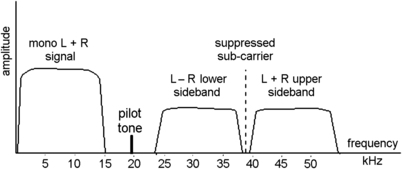 |
| Figure 6.12 The spectrum (graph of amplitude plotted against frequency) for a stereo FM radio signal. This shows the pilot tone and the sidebands of the sub-carrier which are added to the mono signal. This mixture of frequencies is modulated on to the main carrier at around 100
MHz |
Why remove the sub-carrier and supply a 19
kHz sinewave signal? The sub-carrier contributes nothing to the signal; it carries no information. It does, however, require transmitter power, and removing the sub-carrier makes an appreciable saving, allowing the transmitter to carry more of the useful sideband signals. The L
−
R signals cannot easily be demodulated, however, without supplying a 38
kHz signal in the correct phase, and this can be supplied locally at the receiver providing there is a small synchronizing signal available. This is the purpose of the 19
kHz pilot tone, whose frequency can be doubled in the receiver to 38
kHz and then used to correct the phase and frequency of the local oscillator in the receiver. The transmitter power used for the 19
kHz tone can be small, because the amplitude of this signal is small. As a bonus, the 19
kHz wave can be used at the receiver to turn on an indicator that shows that a stereo signal is being received.
Figure 6.13 shows the block diagram for transmission. The separate L and R channel signals are added and subtracted in a circuit called a matrix to give the L
+
R and L
−
R signals, and the L
+
R signal is used to frequency-modulate the main carrier. A master 38
kHz oscillator is used to provide the carrier for the L
−
R signals, and the 38
kHz signal is also used to provide a 19
kHz signal for the pilot tone, which is also frequency-modulated on to the main carrier. The modulated L
−
R signal is passed through a filter which removes the 38
kHz sub-carrier, so that the sidebands can also be frequency-modulated, along with the pilot tone, on to the main carrier. The modulated main carrier is then amplified and used to supply the transmitting antenna.
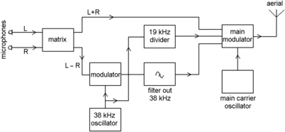 |
| Figure 6.13 A block diagram for the stereo FM transmitter. The L and R signals are mixed to produce the mono signal L
+
R and the smaller difference signal L
−
R which is modulated on to the sub-carrier |
Figure 6.14 is the block diagram of the stages following the demodulator for a stereo FM receiver. The early stages of the receiver are exactly the same as they would be for a mono FM receiver, right up to the point where the FM signal is demodulated, providing three sets of signals. A low-pass filter separates off the L
+
R main signal and a resonant circuit separates out the 19
kHz pilot tone, and this is used to control the phase and frequency of a 38
kHz oscillator. Finally, a high-pass filter separates out the sidebands of the L
−
R signals.
 |
| Figure 6.14 A block diagram for the decoding portion of a stereo FM receiver. Only the portions from the FM demodulator are shown, as the remainder is a standard superhet block diagram |
A circuit called a
phase-sensitive demodulator has inputs of the 38
kHz carrier frequency (obtained by doubling the 19
kHz pilot tone or by using it to synchronize an oscillator) and the L
−
R sidebands, and its output is the L
−
R signal itself. The L
+
R and L
−
R signals are fed into another matrix circuit, producing the L and R signals at the outputs. If you wonder how this is done, think of what happens when you add the inputs:
 and also subtract them:
 so providing the separate L and R signals.
Snags? The stereo signal is more easily upset by interference, particularly car ignition and other spark interference. A mono signal can use a low-pass filter to remove much of the effects, but this would remove the L
−
R signals from a stereo transmission. In addition, the noise level of a stereo transmission is always higher because the bandwidth is greater, and noise depends on bandwidth, the only noise-free signals are those with zero bandwidth, and signals with no bandwidth carry no information. Many FM receivers will automatically switch to mono reception when the noise level is high.
Note
Note
Over the early years of the twenty-first century, FM is certain to be replaced by digital radio, mainly because governments all over Europe have sold the rights to the old FM carrier frequencies to mobile phone companies to provide an alternative to cables between mobile masts. A date in 2015 has been suggested for the UK, but the change will be slow because most digital receivers will sound no different. The uptake of digital radio has been patchy and politicians are reluctant to be labeled as the people who made us change to a system that is perceived as inferior for reception in many areas.
In fact, because the transmitters for digital radio in the UK use the old ITV transmitters (in the days before UHF television) the coverage is poor. This was not such a problem for television because houses had antennae on the roofs. Digital radio receivers that use a simple telescopic whip antenna receive a weak signal, and this can cause a most objectionable sound like boiling mud. In addition, digital radio transmitters often compress the sound signal (see later) so much that the quality suffers compared to a good FM receiver. Some misleading advertising suggests that digital provides a better quality, but this has certainly not been borne out by experience.
Digital radio was supposed to be at its best in cars, where its use eliminates the need to keep retuning to a local FM station as the car leaves one transmitter region and approaches another. The main advantage of digital radio is that a large number of digital radio transmitters can be used in a small amount of bandwidth without interference problems. This is more of an advantage for the broadcasters than for the listeners. Car manufacturers have been very reluctant to make the change, and have had to be bullied into it. The only real use for a digital car radio is that you can cruise around to find where the signal can be picked up, and car manufacturers will probably play safe and install radios that can be switched to FM when the digital signal is unobtainable or of low quality.
Internet Radio
Another possibility for digital radio broadcasting is the use of broadband Internet. This obviously requires a computer, and the sound from computer loudspeakers is fairly poor unless you have invested in high-quality units. With WiFi (Internet signals distributed from a small wireless transmitter in your house) the signals can be relayed to audio equipment, providing a signal quality that can be superior to the DAB signal. If you want to check out what can be achieved, look at the website http://www.shoutcast.com/, which is just one of the many sites offering radio by Internet. At the time of writing Internet radios (not part of a computer, but needing a WiFi signal) were just being advertised in the UK.
Summary
Summary
Stereo FM radio that is compatible with mono broadcasts is made possible by the use of a sub-carrier. The main signal consists of the sum of L and R channel audio signals, and this is a mono signal. The difference signal, L
−
R, is much smaller and is modulated on to a 38
kHz sub-carrier, and this carrier is filtered out, leaving only the sidebands. A 19
kHz pilot tone is added as a way of synchronizing a local oscillator at the receiver. All three signals are frequency-modulated on to the main carrier. At the receiver, the L
+
R signal can be used as a mono signal, and if stereo is required, the pilot tone has its frequency doubled and is used to synchronize the phase of a 38
kHz oscillator. This, along with the sidebands of the sub-carrier, can be used to demodulate the L
−
R signal, and combining the L
+
R and L
−
R signals provides separated L and R audio channel signals. The pilot tone can be used also to switch a stereo indicator lamp on or off. FM will eventually be replaced by digital radio (see Chapter 16).
..................Content has been hidden....................
You can't read the all page of ebook, please click here login for view all page.