Chapter 8. Elements of Television
Scanning to convert image to electrical signals. Resolution. Early mechanical systems. Electronic TV and its pioneers. Simple TV block diagram. Analog TV waveform. Line and field, interlacing. Transmitting TV signals. The composite video signal. Cathode-ray tube principles. Electrostatic and magnetic deflection methods. Linear sweep and flyback. LCD and plasma display methods. Newer forms of display system (OLED, LPD, Tred, LEP). Analog TV monochrome receiver block diagram. I.F response and bandwidth. Demodulator and inter-carrier sound. Sync separator. Equalizing pulses. Color TV. Early sequential systems. Compatible systems. NTSC requirements and RCA system. Monochrome and color-difference signals. Using a sub-carrier. Color signals - hue and saturation. Color sync and back-porch. Color burst. European systems, PAL and SECOM. Color TV cathode-ray tubes. Shadow-mask and aperture grille. Analog receiver circuits. Luminance and chrominance signals. Synchronous demodulator. Color killer circuit.
Television
At the time of writing, the changeover to digital television in the UK is well under way and is due to be completed in the summer of 2011, and the changeover in Australia that started in 2001 should be complete by 2013. The change was completed in the USA in 2009.
The methods of coding the picture information for digital transmission are very different from those used in the older (analog) system, but many of the basic principles of television are much the same. In this chapter we will concentrate first on the older analog system because these receivers can have a long life and may still be in use (using a digital set-top box converter) over the lifetime of this book, and look later at the differences brought about by digital television.
Note
Note
The main benefits of digital television are that it uses less transmitter bandwidth (allowing the government to sell off unwanted frequencies and to license new channels) and is more compatible with flat screens, computers, digital versatile discs (DVDs), and other newer technologies. Older receivers can still be used along with a set-top box, so that owners of satellite dishes had a head start in the use of digital before terrestrial systems (using the existing antenna) such as the UK Freeview system or US OTA became available. For most viewers, digital offers a noticeable improvement in picture quality, and is the only way of delivering high-definition (
HD) pictures.
Scanning
Oddly enough, television has had a rather longer history than radio, and if you want to know more of its origins there was a book called
Birth of the Box, now out of print, which dealt with the fascinating development of this subject. Almost as soon as the electric telegraph (invented in 1837) allowed messages in Morse code (invented in 1838) to be sent along wires, inventors tried to send picture signals, and this activity was spurred on by the invention of the telephone. Sound transmission along wires is simple, because it requires only that the sound waves be converted to electrical waves of the same frequency. A picture, however, is not in a usable wave format, but by the middle of the nineteenth century the principle of
scanning a picture had been established.
Definition
Definition
Scanning means breaking an image into small pieces, reading them in sequence, and coding each of them into an electrical signal.
Suppose, for example, that you drew a picture on a grid pattern such as in Figure 8.1. If each square on the grid can be either black or white, you could communicate this picture by voice signals to anyone with an identical grid by numbering each square and saying which squares were white and which were black. It may sound elementary, but this is the whole basis of both television and fax machines (which are almost identical in principle to the first television transmitters and receivers). This grid could be described as a 12
×
12 picture, but for television we need a much larger number of squares, typically about 500
×
300. Currently, computers use 640
×
480 as a minimum, with 800
×
600, 1024
×
768, or higher, more often used. Analog television more often specifies only the
vertical resolution in terms of the number of lines (currently 625 in the UK and Europe, 525 in the USA), though not all of the lines carry picture information. This makes it difficult to compare the performance of analog television receivers with computer monitors. HD television displays can use 1024
×
600 for 16:9 pictures (see later).
 |
| Figure 8.1 A simple image consisting of black or white squares. We can imagine this being built up line by line by scanning across and down and deciding whether a square should be filled or not |
Early television systems, patented around 1870 by Nipkow and Rosing in St Petersburg, and subsequently constructed by John Logie Baird in the late 1920s and early 1930s, used mechanical scanning (with rotating discs or mirrors) and were confined initially to still pictures of around 30 scanned lines, in black and white, with no shades of gray. Television as we know it had to wait until electronic components had been developed, and in particular, the receiver cathode-ray tube (CRT) and the camera tube.
By the early 1930s, however, Philo Farnsworth in San Francisco had demonstrated that electronic television was possible (at almost the same time as Baird had made a sound broadcast declaring that CRTs could never be useful for television). Also at that time, a form of radar had been used to measure the distance from Earth of the reflecting layers of charged particles in the sky (the Heaviside and Appleton layers). These two forms of technology were to play decisive roles in the development of electronics in the twentieth century.
The attraction of the CRT is that it can carry out scanning by moving an electron beam from side to side and also from top to bottom, tracing out a set of lines that is called a
raster. Nothing mechanical can produce such rapid changes of movement as we can obtain by using an electron beam, so that most of the television pioneers realized that this was the only method that would be acceptable for reasonable definition, though the cinema industry of those days (which backed Baird) still believed that mechanical systems might prevail. By the 1930s, it was becoming acknowledged that any acceptable form of television receiver would certainly use a CRT, and the main research effort then went into devising a form of CRT that could be used for a television camera. The principles of such a tube were:
Without going into details, then, a camera CRT must allow the image projected on to the face of the tube to be converted into electron charges, and these charges are scanned by an electron beam from which it must produce a signal current or voltage that can be amplified so as to represent the brightness of each part of the scanned picture.
• a light-sensitive surface on which an image could be projected using a lens, causing electrons to leave the surface
• a scanning electron beam which could replace the electrons lost from the light-sensitive surface
• some method of detecting how many electrons were being replaced for each portion of the image (this is the signal current).
Synchronization
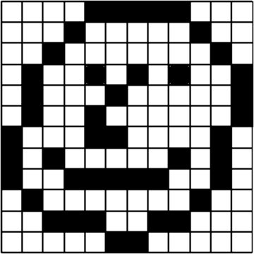
The problems of developing CRTs were only part of the story. A remarkable lecture in 1911 by J.J. Campbell Swinton outlined a television system that we can recognize today and which was at least twenty years ahead of its time. It imagined that both camera and receiver would use CRTs, and for the first time emphasized that the scanning had to be synchronized, and that this could be done using start-of-scan signals that had also to be transmitted so that the scanning at the receiver would remain in step with the scanning at the transmitter. Figure 8.2 shows Campbell Swinton’s drawing. If we can ever credit anybody with inventing television as we know it, the honors have to be shared between Campbell Swinton and Philo Farnsworth. This leaves Baird with the honor of inventing the word ‘television’ and showing that the 1870 system could be used as a primitive form of fax machine. Baird could rightly claim that he proved that television was possible.
Note
Note
The use of camera tubes declined rapidly towards the end of the 1990s because of the development of light-sensitive semiconductor panels of the charge-coupled device (CCD) type. These have superseded the types of CRT used for television cameras, making cameras much lighter and less bulky. Their development has also made possible the camcorder that combines a television camera and video recorder in one package, and the most recent digital camcorders that fit into the palm of your hand. CCD units are also used in digital still cameras. For reception, flat-screen technologies have almost totally replaced CRTs.
 |
| Figure 8.2 A drawing of Campbell Swinton’s proposal for an electronic television system |
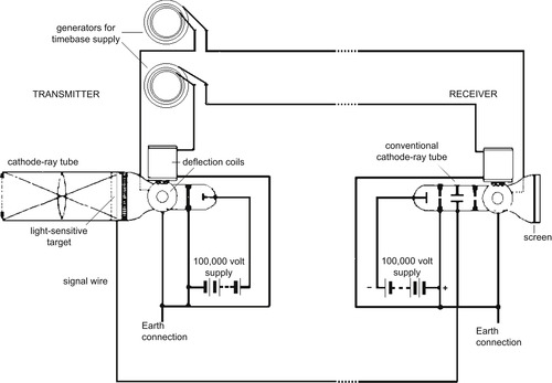
We can make a block diagram (Figure 8.3) for a simple, more modern television system that follows closely along the lines laid down by Campbell Swinton. This shows a camera tube which is scanned by signals from a generator, and these signals are also sent to a transmitter along with the amplified vision (
video) signals from the tube. These signals can be sent down a single wire (or they can be modulated on to a radio wave) to the receiver where the video signals are separated from the scanning signals, and the separate signals are applied to the receiver CRT. This is virtually a block diagram for the first electronic television systems used from 1936 onwards.
 |
| Figure 8.3 A block diagram for a more modern version of a simple electronic television system |
The most remarkable aspect of the development of electronic television in the 1930s was that so many new problems were tackled at the same time. The television signal needed a large bandwidth, thousands of times greater than anything that had been used in radio. The carrier frequency had to be high and very few radio tubes used at the time were suitable to be used at such high frequencies. Circuits had to be invented to generate the scanning waveforms, which needed to be of sawtooth shape (see Chapter 1). A system had to be worked out for allowing the receiver to generate its own sawtooth scanning waveform, but keep these perfectly synchronized with the scanning at the transmitter. Not until the space race would any team of engineers tackle so many new problems together on one project.
Summary
Summary
Though primitive television systems used mechanical scanning, television as we know it was impossible until electronic methods of scanning a picture were devised. The scheme outlined by Campbell Swinton in 1911 was the basis of modern television, and it made use of a form of CRT at both transmitter and receiver. This scheme also emphasizes the use of synchronizing signals that would be used by both transmitting and receiving equipment.
The Analog Television Waveform
The problems of analog television are illustrated by looking at the shape of the television waveform. Like any wave, this is a repeating pattern, but the shape is much more complicated than that of a sound wave. In particular, the wave contains some portions that have very sharp edges, and these edges are vital to synchronization. A typical single wave for a black-and-white television system of the 1950s is shown in Figure 8.4 (a), along with a portion of the waveform that is transmitted at the end of a ‘field’ when all of a set of lines have been scanned and the beam is at the bottom of the tube face (Figure 8.4 b).
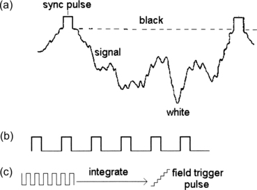 |
| Figure 8.4 (a) The standard analog television signal (for a black-and-white picture), showing the signal level for one line, and (b) the pulses that are transmitted at the end of a field. The signals are shown as they appear when modulated on to the carrier, with the tips of the sync pulses representing peak carrier amplitude. The effect of integrating the field pulses is illustrated in (c) |
The small rectangular portion of the wave in Figure 8.4 (a) is the line-synchronizing pulse (‘line sync’), and it is used in the receiver to ensure that the electron beam starts scanning across just as the first part of the video wave reaches the receiver. The video wave itself will have a shape that depends on the amounts and position of dark and light parts of the picture across one line. Mechanical television originally used a 30-line scan, but electronic television started in the UK with 405 lines (525 lines were used in the USA), a huge improvement in resolution that allowed relatively fine detail to be seen. The video amplitude ranges between black and peak white, and the synchronizing pulses are in the opposite direction, lower than the level that is used to represent black so that nothing can be seen on the screen when the pulses are transmitted.
At the end of a set of lines, the waveform changes. There is no video signal, just a set of more closely spaced synchronizing pulses. These are integrated at the receiver to generate a
field synchronizing pulse which will bring the beam back to the top left-hand corner of the screen ready to scan another set of lines. As before, these pulses have an amplitude that is lower than black level (‘blacker than black’) so that they do not cause any visible disturbance on the screen.
As it happens, using a full set of 405 lines to make a picture was out of the question when television started in 1936 (and it would still cause problems on an analog system even now). The trouble is that a waveform consisting of 405 lines repeated 50 times per second needed too much bandwidth. Pioneers in the USA had even more to cope with, using 525 lines at 60 pictures per second. The answer that evolved on both sides of the Atlantic was
interlacing. Interlacing, using the UK waveform as an illustration, consists of drawing the odd-numbered lines in
 second and the even-numbered lines of the same picture in the next
second (Figure 8.5). This way, the whole picture is drawn in
second and the even-numbered lines of the same picture in the next
second (Figure 8.5). This way, the whole picture is drawn in
 second, and the bandwidth that is needed is only half as much as would be needed without interlacing. Interlacing is still used on analog television and digital television pictures, though it is not used on computer monitors because on the small bright images of a monitor the use of interlace can cause a flicker which is visually disturbing.
Note
Summary
Note
Digital television transmissions send out interlaced signals so that they can be displayed on television receivers that use a CRT. Modern flat-screen television receivers using liquid crystal display (LCD) or plasma displays do not need interlacing (which can cause problems) and so the received signal is deinterlaced. Computer monitors do not use interlacing at all. Eventually, interlacing will be discontinued for television broadcasts.
Summary
The analog television waveform is not a symmetrical wave of fixed shape. The synchronizing pulse for each line occurs at regular intervals, but the waveshape that follows this pulse depends on the distribution of light and shade in that line of the picture. The use of interlacing, scanning only half of the total number of lines in each vertical sweep, reduces the bandwidth by half without degrading the picture quality. Interlacing is not required for flat-screen displays, but is still used on the broadcast signal for compatibility with CRT receivers.
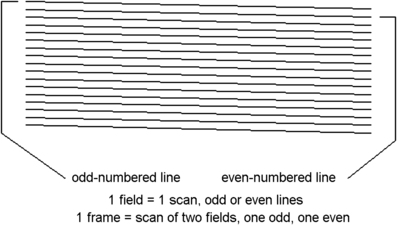 |
| Figure 8.5 The principle of interlacing. This allows a more detailed analog picture to be transmitted without using an excessive bandwidth |
Transmission
We can look now at a block diagram of the studio and transmission side of black-and-white television in the days when CRTs ruled. We will look later at the additions that have to be made for color.
Television transmission at its simplest starts with a television camera, which is fed with synchronizing pulses from a master generator. Light from the scene that is to be transmitted is focused through a lens on to the face of the camera tube, and this light image is converted into an electron charge image inside the front section of the tube. The scanning electron beam discharges this, and the discharge current is the
video signal. This is the starting point for the block diagram of Figure 8.6. The video signal, which is measured in microvolts rather than in millivolts, has to be amplified, and the synchronizing pulses are added. The generator that supplies the synchronizing pulses also supplies the scans to the camera tube. The complete or
composite video signal that contains the synchronizing pulses is taken to the modulator where it is amplitude-modulated on to a high-frequency carrier wave.
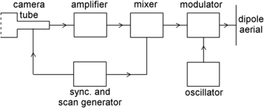 |
| Figure 8.6 Television transmission from camera to antenna. This block diagram shows a simplified version of the transmission of a monochrome picture from a camera of the older type using a camera tube |
Modern analog television systems modulate the signal so that peak white is represented by the
minimum amplitude of carrier and the synchronizing pulses by the
maximum amplitude. In the original UK television system the signals were modulated the other way round, with peak white represented by maximum carrier amplitude, but this method allowed interference, particularly from car-ignition systems, to show as white spots on the screen. When the system changed to 625 lines in 1968, maximum carrier amplitude was used for the sync pulse peaks in line with the methods used in other countries. Using this system, interference causes black spots that were much less noticeable, and the compulsory use of suppressor resistors in car-ignition systems has almost eliminated the main source of television interference.
The sound signal has been omitted from this to avoid complicating the diagram. The sound is frequency-modulated on to a separate carrier at a frequency higher than that of the vision carrier, and is transmitted from the same antenna.
Summary
Summary
The analog video signal is generated from a camera tube or a CCD panel and is amplified and combined with synchronizing signals to form the composite video signal. This is amplitude-modulated on to a carrier with the tips of the sync pulses represented by peak carrier amplitude. The sound signal is frequency modulated on to a separate carrier which is at a frequency 6
MHz higher than the vision signal.
Modern Television Displays
Cathode-Ray Tubes
The CRT is an active component that nowadays is just about the only device you are likely to come across that uses the same principles as the old-style radio tubes. The CRT converts an electrical signal into a light pattern, and though the principle was discovered in the 1890s the technology for mass production was not available until the 1930s and by that time was being pushed on by the needs of radar as much as by those of television. Nowadays, CRTs are still around in older television receivers, but they are rapidly being replaced by modern flat-screen displays that use semiconductors and are better suited to modern digital television signals.
Definition
Definition
The CRT can be used to convert variations of voltage into visible patterns, and is applied in instruments (oscilloscopes), for television, and for radar, though their use in these applications is rapidly dying out.
The three basic principles of the CRT are that:
Note
• Electrons can be released into a vacuum from very hot metals.
• These electrons can be accelerated and their direction of movement controlled by using either a voltage between metal plates or a magnetic field from a coil that is carrying an electric current.
• A beam of electrons striking some materials such as zinc sulfide will cause the material (called a
phosphor) to glow, giving a spot of light as wide as the beam.
Note
Do not be misled by the name: a phosphor does not contain phosphorus (though it can contain several nasty poisons). The name simply means a substance that glows.
Nothing is ever as simple as basic principles might suggest. There are very few metals that will not melt long before they are hot enough to emit electrons, and at first, only the metal tungsten was deemed suitable. Tungsten was used for radio tubes and for CRTs until a chance discovery that a mixture of calcium, barium, and strontium oxides, comparatively cheap and readily available materials, would emit electrons at a much lower temperature, a dull-red heat. By the early 1930s, ‘dull-emitter’ tubes were being mass produced, and some CRTs were being manufactured for research purposes.
Figure 8.7 shows a cross-section of a very simple CRT. The
cathode is a tiny tube of metal, closed at one end and with that end coated with a material that emits electrons when it is red hot. A coil of insulated wire, the
heater, is used to heat the cathode to its working temperature. Because the far end of the tube contains conducting material at a high voltage (several kilovolts), electrons will be attracted away from the cathode.
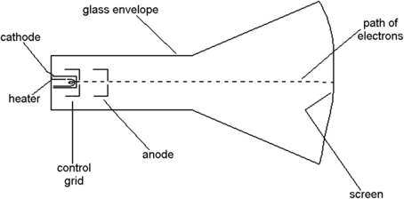 |
| Figure 8.7 A diagram of a very simple type of cathode-ray tube which can produce an electron beam that in turn will make a spot of light appear on the screen. Details of connections to a base have been omitted |
These electrons have to pass through a pinhole in a metal plate, the
control grid. The movement of the electrons through this hole can be controlled by altering the voltage of the grid, and a typical voltage would be some 50
V
negative compared to the cathode. At some value of negative grid voltage, the repelling effect of a negative voltage on electrons will be greater than the attraction of the large positive voltage at the far end of the tube, and no electrons will pass the grid: this is the condition we call
cut-off.
Electrons that pass through the hole of the grid can be formed into a beam by using metal cylinders at a suitable voltage (Figure 8.8 shows a set of typical voltages for a small CRT). By adjusting the voltage on one of these cylinders, the
focus electrode, the beam can be made to come to a small point at the far end of the tube. This end is the screen, and it is coated with the
phosphor that will glow when it is struck by electrons. The phosphor is usually coated with a thin film of aluminum so that it can be connected to the final accelerating (
anode) voltage. The whole tube is pumped to as good a vacuum as is possible; less than a millionth of the normal atmospheric pressure.
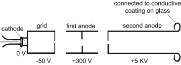 |
| Figure 8.8 Typical voltages on the electrodes of a small cathode-ray tube as would be used in oscilloscopes at one time |
This arrangement will produce a point of light on the center of the screen, and any useful CRT must use some method of moving the beam of electrons. For small CRTs used in traditional oscilloscopes a set of four metal plates can be manufactured as part of the tube and these
deflection plates will cause the beam to move if voltages are applied to them. The usual system is to arrange the plates at right angles, and use the plates in pairs (Figure 8.9), with one plate at a higher voltage and the other at a lower voltage compared to the voltage at the face of the tube. This system is called
electrostatic deflection.
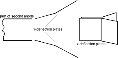 |
| Figure 8.9 Using metal plates to deflect the electron beam. The plates are sloped and bent to ensure that the deflected beam does not strike them |
There is an alternative method for deflecting the electron beam which is used for larger tubes, particularly for CRTs in computer monitors, radar, and television uses. A beam of electrons is a current flowing through a vacuum, and magnets will act on this current, deflecting the beam. The easiest way of doing this is to place coils around the neck of the tube and pass current through these coils to control the beam position on the face of the tube. This magnetic deflection method (Figure 8.10) is better suited for large CRTs such as were for many years used for television, monitors, or radar.
Summary
Summary
The CRT can use either electrostatic or magnetic deflection, so that the beam of electrons can have its direction altered, allowing the light spot to appear anywhere on the face of the tube. Magnetic deflection has been used for large televisions, computer monitors, and radar tubes; electrostatic deflection for the smaller tubes for measuring instruments. Nowadays, all the applications use flat-screen displays instead of a CRT.
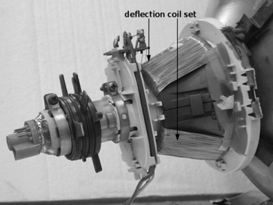 |
| Figure 8.10 Using magnetic deflection, with coils wrapped around the neck of the tube. This form of deflection allows very short tubes to be constructed |
The form of side-to-side deflection that is most common for CRTs is a
linear sweep. This means that the beam is taken across the screen at a steady rate from one edge, and is returned very rapidly (an action called
flyback) when it reaches the other edge. To generate such a linear sweep, a sawtooth waveform (Figure 8.11) is needed. An electrostatic tube can use a sawtooth voltage waveform applied to its deflection plates, and a magnetic deflection can use a sawtooth current applied to its deflection coils. The difference is important, because the electrostatic deflection requires only a sawtooth voltage with negligible current flowing, but the magnetically deflected tube requires a sawtooth
current, and the voltage across the deflection coils will not be a sawtooth, because the coils act as a differentiating circuit. In fact, the voltage waveform is a pulse, and this is used in television receivers to generate a very high voltage for the CRT (see later, this chapter).
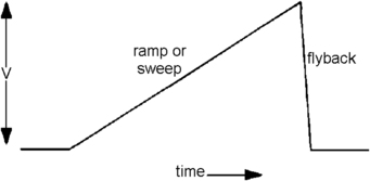 |
| Figure 8.11 The sawtooth or sweep wave that is needed to scan a cathode-ray tube. For an electrostatically deflected tube, this would be a voltage waveform applied to plates; for a magnetically deflected tube this is a current waveform applied to coils |
Liquid Crystal Display and Plasma Screens
Vacuum CRTs are now almost obsolete, for displays can now be made using LCDs and plasma principles. The principle of LCDs is that some liquid materials (including the cholesterol that clogs up your arteries) respond to the electric field between charged plates, and line up so that one end of each large molecule points towards the positive plate and the other end to the negative plate. In this condition, light passing through the material is polarized, so that if you look at the material through Polaroid™ sheet, the amount of light that passes alters when you rotate the Polaroid sheet. Polaroid is the material that is familiar from sunglasses that can cut out unwanted glare from water.
An LCD uses a set of parallel plates, of which one is a transparent conducting material, and one wall of the display is made of polarizing material (Figure 8.12). With no voltages applied, light passes through the polarized front panel, through the liquid, and is reflected from the metal backplate and out again. When a voltage is applied, the liquid between plates is polarized, and light can no longer be reflected back, making that part of the display look black. This type of display has been used for many years for calculators because it consumes very little power and yet gives a very clear output in good lighting conditions. It needs a source of light, however, either transmitted (light behind the screen) or reflected (light striking the front of the screen).
Note
Note
The shapes that are to be produced are determined by the shape of the film of transparent conducting material at the front of the cell. For example, if this film is deposited in the shape of a ‘2’, the cell will show this digit when activated.
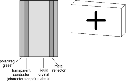 |
| Figure 8.12 Simplified cross-section of a liquid crystal display cell |
For use as a display for portable computers, each position on a screen must be capable of being individually controlled, making the construction of such a screen much more difficult than that of a calculator display. For example, the usual older type of computer screen is required to be able to display at least 640
×
480 dots, a total of 307,200 dots; and that means 307,200 tiny LCD cells, each of which can be set to black or clear. For color displays, used almost universally now, dots are grouped in threes, one dealing with red, one with green, and one with blue. LCDs of this type have to be combined with integrated circuits to make the connections usable, and the later thin-film transistor (TFT) types are active, meaning that one or more integrated transistors will control each dot. Rather than depending on light reflection, these displays are made with a low-consumption backlight that shines through the clear portions of the display.
The technology of constructing LCD screens has now evolved to thin color screens with dot patterns of 1280
×
1024 or more, and these have now replaced the older CRT types of displays in computer monitors. Television receivers are also using these types of screen, and at the time of writing most television receivers offer HD, typically 1280
×
1024. A recent development is the use of light-emitting diodes (LEDs) to provide the backlight.
Plasma displays use a very different principle. Each dot in a plasma screen is produced by a tiny glass tube containing a gas and two electrical connections. A voltage between these connections will make the gas glow, and by specifying the appropriate gas in each tube we can produce the three basic colors of red, green, and blue which, when illuminated in the correct proportions, will produce white light (or any color). This system is best applied to large screens in which the larger dots are more appropriate; it is difficult to make in smaller sizes with high definition. One considerable advantage is that it needs no backlight, because the backlight for an LCD screen requires a considerable amount of power unless the LED system is used.
In the lifetime of this book you can expect to see several other forms of display technology such as organic light-emitting diode (OLED), laser phosphor display (LPD), trichromatic reflective electronic display (Tred), light-emitting polymer (LEP), and others that are still, at the time of writing, in the very early stages of development. Which of these we shall be using depends very much on factors such as ease of manufacture, lifetime, and price.
Analog Television Receiver
An analog television receiver for monochrome (Figure 8.13) has to deal with several signal-separating actions. The signal from the antenna is processed in a straightforward superhet type of receiver, and the methods that are used differ only because of the higher frequencies and the larger bandwidth. The vision and sound carriers are received together, and so the intermediate-frequency (IF) stages need to have a bandwidth that is typically about 6
MHz, enough to take the wideband video IF and the sound IF together. The real differences start at the demodulation block. A typical IF range is 35–39.5
MHz (for amplitude 6
dB down from maximum).
Note
Note
For a digital television system, the superhet portion is the same as it would be for an analog receiver, but the processing of signals after the demodulation block is very different.
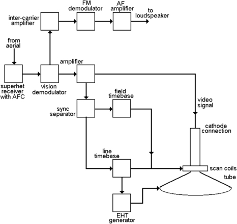 |
| Figure 8.13 A monochrome analog receiver block diagram. The diagram shows all of the superhet circuits as one block, and concentrated on the vision (luminance) and sound (audio) signals |
Figure 8.14 illustrates the IF response, which must be broad enough to include both sound and vision carriers and sidebands, yet provide enough filtering to exclude signals from the adjacent frequencies. These adjacent frequencies arise from the mixing of the superhet oscillator frequency with the signals from other transmitters.
Note
Note
Figure 8.14 also shows the frequency that is used as the sub-carrier for color signals (see later).
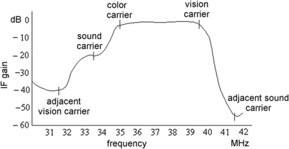 |
| Figure 8.14 The intermediate-frequency (IF) response of a typical receiver, showing the relative signal strengths over the bandwidth. The frequency marked as color carrier is important for color receivers |
The demodulator is an amplitude demodulator, and at this stage the composite video signal with its sync pulses can be recovered. The effect of this stage on the IF for the sound signal is to act as a mixer, and since the sound IF and the vision IF are 6
MHz apart, another output of the demodulator is a frequency-modulated 6
MHz signal (the
intercarrier signal) which carries the sound. This is separated by a filter, further amplified and (FM) demodulated to provide the sound output.
The video signal is amplified, and the synchronizing pulses are separated from it by a selective amplifier. These pulses are processed in a stage (the
sync separator) which separates the line and the field pulses by using both differentiating and integrating circuits (Figure 8.15). The differentiated line pulses provide sharp spikes that are ideal for synchronizing the line oscillator, and the field pulses build up in the integrator to provide a field synchronizing pulse. The effect of the differentiator on the field pulses is ignored by the receiver because the beam is shut off during this time, and the effect of the line pulses on the integrator is negligible because these pulses are too small and too far apart to build into a field pulse.
Note
Note
These pictures of sync pulses are simplified. At the end of a field or frame, there are five pulses called
equalizing pulses placed before and following the field synchronizing pulses. The aim of this is to give time for the circuits to adjust to the differences between the end of a field and the end of a complete frame (there is half-a-line difference in timing).
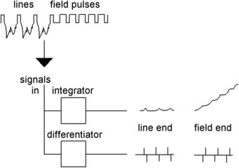 |
| Figure 8.15 How sync pulses are separated by integrating and differentiating circuits. The output of the differentiator during the field interval is ignored |
The synchronized line and field timebase oscillators drive the output stages that deflect the electron beam, using magnetic deflection (passing scan currents through coils). The fast flyback of the line scan current causes a high voltage across the transformer that is used to couple the line scan output to the deflection coils, and this voltage is used to generate the extra-high-tension (EHT) supply of around 14–24
kV that is needed to accelerate the beam.
Meantime, the video signal has been amplified further and is taken to one terminal (cathode) of the CRT, with another terminal (grid) connected to a steady voltage to control brightness. Another set of circuits, the power supply unit (PSU), uses the alternating current (AC) mains supply to generate the steady voltages that will be used by the receiver circuits.
Summary
Summary
A monochrome receiver uses the normal superhet circuit up to the vision demodulator, where the composite video signal is recovered and the 6
MHz intercarrier sound signal is filtered off, demodulated, and amplified. The composite video signal is passed to a sync separator which removes the video portion and allows the two sets of synchronizing pulses to be separated and used to synchronize the timebases. The video signal is applied to the grid (or cathode) of the CRT, and the timebase signals to deflection coils. The very large pulses that exists on the line timebase output are stepped up by a transformer and used to generate the EHT supply of 14
kV or more for the CRT.
Color Television
Though Sam Goldwyn is reputed to have said that he would believe in color television when he saw it in black and white, the idea of color television is not new, and methods for transmitting in color have been around as for as long as we knew that black-and-white (monochrome) television was possible. Color television, like color printing and color photography (both demonstrated in the 1880s), relies on the fact that any color seen in nature can be obtained by mixing three primary colors. For light, these colors are red, green, and blue, and the primary colors used by painters are the paint colors (red, yellow, and blue) that absorb these light colors. To obtain color television, then, you must display together three pictures, one consisting of red light, one of blue light, and one of green light. This implies that the color television camera must generate three separate signals from the red, blue, and green colors in an image.
All of the early color television systems worked on what is called a
sequential system, meaning that the colors were neither transmitted nor seen at the same time, relying on the optical effect called persistence of vision. This means that the eye cannot follow rapid changes, so that showing the red components of a picture followed rapidly by the blue and the green will appear to the eye as a complete color picture rather than flashing red, blue, and green. We rely on the same effect to fool the eye into believing that we are watching a moving picture rather than a set of still images.
A typical early method was the
frame sequential system. Each picture frame was transmitted three times, using a different color filter for each of a set of three views so that though what was transmitted was black and white, each of a set of three frames was different because it had been shot through a color filter, one for each primary color. At the receiver, a large wheel was spinning between the viewer and the television screen, and this wheel carried a set of color filters. The synchronization was arranged so that the red filter would be over the CRT at the time when the frame containing the red image was being transmitted, so that this filter action put the color into the transmitted monochrome picture. The main snag with this system is that the frames must be transmitted at a higher rate to avoid flickering, and there are also problems with compatibility and with the synchronization of the wheel (and its size). A more realistic option was a line-sequential system, with each line being shown three times, once in red, once in green, and once in blue.
Several early television systems were devised to show still color pictures, but the first commercially transmitted color television signals were put out in 1948 by CBS in New York, using a combination of electronic and mechanical methods. The system was not successful, and a commission on color television decided that no scheme could be licensed unless it was
compatible. In other words, anyone with a monochrome receiver had to be able to see an acceptable picture in black and white when watching a color broadcast, and anyone with a color receiver had to be able to see an acceptable black-and-white picture when such a picture was being transmitted (to allow for the use of the huge stock of black-and-white films that television studios had bought). This ruled out the use of frame-sequential systems, and almost every other consideration ruled out the use of mechanical systems allied to the CRT.
Summary
Summary
Color television, like color photography, depends on detecting the red, green, and blue light amplitudes in an image, since all natural colors can be obtained from mixtures of these pure light colors. A color television camera must therefore produce three separate signals, which can be R, G, and B, or mixtures from which separate R, G, and B signals can be obtained. Though early television systems had been able to produce pictures using sequential color, these systems were not compatible with monochrome transmissions and were abandoned in favor of a simultaneous system in 1952.
Radio Corporation of America (RCA) had been working on simultaneous systems throughout the 1940s, and their demonstrations in 1952 convinced the commission, the National Television Standards Committee (NTSC), that the RCA system was suitable. All other systems have taken this system as a basis, but differences in details mean that NTSC television pictures are not compatible with the PAL color system used in Germany, the UK, and other parts of western Europe, or the SECAM system used in France, former French colonies, and eastern Europe. This is also why you cannot exchange video cassettes or DVDs with friends overseas, and the hope that digital systems might be compatible has been dashed because the method of coding sound used in the USA is not the same as that used in Europe, though the vision signals are compatible. Even DVDs have to be separated into PAL, NTSC, and SECAM groups.
Let’s start with the portions that are common to all analog systems. To start with, the image is split into red, green, and blue signal components, using prisms, so that three separate camera tubes or semiconductor CCD detectors can each produce a signal for one primary color. This is the starting point for the block diagram of Figure 8.16. The signals are mixed to form three outputs. One is a normal monochrome signal, called the
Y signal. This is a signal that any monochrome receiver can use and it must be the main video signal so as to ensure compatibility. The other two outputs of this mixer are called
color-difference signals, obtained by using different mixtures of the red, green, and blue signals. These color-difference signals are designed to make the best use of the transmission system and are of considerably lower amplitude than the monochrome signal, because in any television signal, the monochrome portion always carries much more information. Color is less important, and all the fine details of a picture can be in monochrome only because the eye is less sensitive to color in small areas. These color-difference signals are lettered
U and
V.
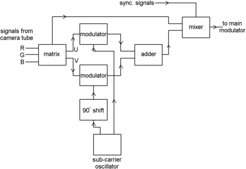 |
| Figure 8.16 The PAL system. A block diagram, simplified, of the processes at the transmitter |
The color-difference signals are transmitted using a
sub-carrier, a method that we have looked at already in connection with stereo radio. This time, the use of the sub-carrier is much more difficult because it has to carry more than one signal. To ensure compatibility, the sub-carrier frequency must be within the normal bandwidth of a monochrome signal, so that you would expect it to cause a pattern on the screen. As it happens, by choosing the sub-carrier frequency carefully, and keeping its amplitude low, it is possible to make the pattern almost invisible. The other problem is that this sub-carrier has to be modulated with
two signals, and this is done by modulating one color-difference signal on to the sub-carrier directly (using amplitude modulation) and then using a phase-shifted version of the sub-carrier, with phase shifted by 90°, and modulating the other color-difference signal on to this phase-shifted sub-carrier.
Note
Note
Modulating two waves of the same frequency but with 90° phase difference is equivalent in effect to modulating both the amplitude and the phase of the same carrier. It is just like the way that stereo recordings vibrate a stylus in directions at right angles to each other.
If you remember that a 90° phase shift means that one wave is at zero when the other is at a maximum, you will appreciate that adding these two modulated sub-carriers together does not cause them to interfere with each other. The doubly modulated sub-carrier can now be added to the monochrome signals (remember that the sub-carrier has a considerably lower amplitude) and the synchronizing signals are added. This forms the color composite video waveform which can be modulated on to the main carrier. What this amounts to is that the amplitude of the modulated signal represents the saturation of color and the phase of the modulated signal represents the hue.
Definition
Definition
The
hue is the color, the wavelength of the light, and
saturation measures how intense the hue is. Most natural colors have low saturation values, meaning that these colors are heavily diluted with white.
Synchronizing is not just a matter of the line and field pulses this time. A color receiver has to be able to generate locally a copy of the sub-carrier in the correct phase so that it can demodulate the color signals. To ensure this, ten cycles of the sub-carrier are transmitted along with each line-synchronizing pulse, using a time when the normal monochrome signal has a gap between the line-synchronizing pulse and the start of the line signal (Figure 8.17). This
color sync interval is called the
back porch of the synchronizing pulse. The illustration also shows how some colored bars appear on a signal, as viewed by an oscilloscope (see Chapter 17). The sub-carrier in these signals is represented by shading. If the sub-carrier were not present, these bars would appear in shades of gray.
Summary
Summary
To ensure compatibility, the normal monochrome signal must be modulated on to the main carrier in the usual way. The color-difference signals are then transmitted by modulating them on to a sub-carrier whose frequency is carefully chosen to cause the minimum of interference with the monochrome signal. One color-difference signal is amplitude-modulated on to the sub-carrier directly, and the other is amplitude modulated on to a sub-carrier of the same frequency but phase shifted by 90°. These signals are added to the monochrome signal, and nine cycles of the 0° phase sub-carrier signal are inserted following each line-synchronizing pulse so that the receiver can locally generate a sub-carrier in the correct phase.
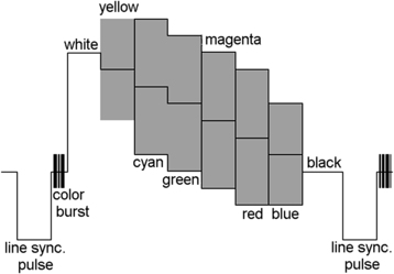 |
| Figure 8.17 The color burst and color bars. The color burst consists of ten cycles (actually 10
±
1 cycles) of sub-carrier located in the back porch of each line-sync pulse. The diagram also shows the waveforms corresponding to color bars; this cannot, of course, indicate the phase of the sub-carrier |
The Three Color Systems
Compatible analog color television broadcasting started in the USA in 1952, using a scheme that was very much as has been outlined here (though the color difference signals were not formed in the same way). In the early days the NTSC system suffered from color problems, with viewers complaining that they constantly needed to adjust the color controls that were fitted to receivers, hence the old joke that NTSC stood for ‘never twice the same color’. The problem was that during transmission of the signals, changes in the phase of the carrier caused by reflections had a serious effect on the sub-carrier, causing the color information to alter. This is because the phase of the color signal carried the hue information. Though subsequent development has greatly reduced these problems, the basic NTSC system has remained virtually unaltered.
By contrast, the color television systems used in Europe were designed much later with an eye on the problems that had been experienced in the USA. Though the principle of transmitting a monochrome signal along with a sub-carrier for two color signals has not changed, the way that the color sub-carrier is used has been modified, and so too has the composition of the color signals. There are two main European analog systems, PAL and SECAM. The PAL system was evolved by Dr Bruch at Telefunken in Germany, and the SECAM system by Henri de France and a consortium of French firms. SECAM is used in France, in former French colonies, and in eastern Europe, but the PAL system has been more widely adopted. Only the American-influenced countries (North and South) and Japan retain the modern form of the NTSC system.
The PAL system uses the color-difference signals that are called U and V, with the color mix carefully chosen so that these signals need only a small (and equal) bandwidth. What makes the essential difference, however, is that the V signal, which carries most of the hue information, is inverted on each even-numbered line, and the signal that is used in the receiver is always the average of one line and the preceding line. If there has been a phase shift in the sub-carrier caused by conditions between the transmitter and the receiver, then subtracting the V signals of one line from the V signals of the following line will have the effect of canceling out the changes. Since the V signals carry the hue information, this eliminates the changes of color that were such a problem with the original NTSC signals. The snag is that the averaging of adjacent lines has the effect of reducing the vertical resolution for color to half of its value for monochrome, but, since the eye is less sensitive to color, this is not as much of a problem as it might appear.
By contrast, the SECAM system works by using frequency modulation of the sub-carrier, using the U signal on one line and the V signal on the next. As for the PAL system, the information of two lines has to be gathered up to provide the signals for each one line, reducing the vertical resolution for color.
Summary
Summary
The European analog color television systems have been designed from the start to avoid the problems caused by phase changes of the color signal. The PAL system does this by inverting the V signal on alternate lines and averaging the signals at the receiver to cancel out the effects of phase change. SECAM operates by transmitting U and V signals on alternate lines. In both cases, the color information in two successive lines is always averaged.
Color Television Tubes
The first color television receivers depended very heavily on the CRT, and the type that was universally used in the latter days was the color-stripe type. This replaced the color-dot type that was used in 1952 and continued in use until the late 1960s. These tubes allow simultaneous color output, meaning that the colors of a picture are all being displayed together rather than in a sequence, so that color television tubes have to use three separate electron guns, one for each primary color.
Figure 8.18 shows a magnified view of a portion of the screen of a typical tube. The glowing phosphors are arranged as thin stripes, using three different materials that glow each in a primary color when struck by electrons. These stripes are narrow, and typically a receiver tube would use at least 900 stripes across the width of the screen. Tubes for computer monitors used a much larger number, and this was reflected in the price of a monitor compared to a television receiver of the same screen size. CRT monitors are by now seldom used because the size of screen and the requirement for high resolution made the use of LCD flat panels economically possible.
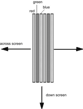 |
| Figure 8.18 The arrangement of phosphor stripes on the screen of a color display tube. Each dot viewed on the tube face consists of portions of a set of three stripes |
The color tube contains three separate electron guns (Figure 8.19). Between the screen and the electron guns and close to the screen there is a metal mask (formerly called the
shadowmask when round apertures were used, later called the
aperture grille) consisting of narrow slits. These slits are lined up so that the electrons from one gun will strike only the phosphor stripes that glow red, the electrons from the second gun will strike only the stripes that glow green, and the electrons from the third gun will hit only the blue stripes. We can therefore call the electron guns
red,
green, and
blue because these are the colors that they will produce on the screen. If we can obtain a set of video signals for these guns, identical to the original red, green, and blue signals from the camera tubes, we should achieve an acceptable copy of the television image in color.
Note
Summary
Note
Another approach to display is the use of projection displays, using either small (about 7 inches) CRTs, or LCD panels with bright illumination. These displays can be very impressive, though some types need to be viewed in semi-darkness for best results.
Summary
The display tube is the heart of any CRT color television receiver. All modern color CRTs use a set of phosphor strips, arranged in a recurring R, G, B pattern. Close to this screen, a metal mask ensures that each of the three electron guns will project a beam that can hit only one color strip each, so that signals to these guns will be R, G, and B signals, respectively. The use of LCDs has advanced so rapidly that few (if any) television receivers using a CRT are now available.
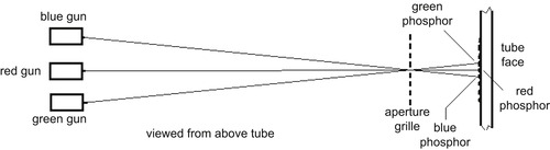 |
| Figure 8.19 How the three guns of a color tube are arranged. The aperture grille ensures that electrons from the ‘red’ gun strike only red-glowing phosphor stripes, and similarly for the other two guns |
Analog Receiver Circuits
A fair amount of the circuitry of an analog color television receiver is identical to that of a monochrome receiver. The superhet principle is used, and the differences start to appear only following the vision detector, where the video signal consists of the monochrome signal together with the modulated sub-carrier. The U and V color-difference signals have to be recovered from this sub-carrier and combined with the monochrome signal to give three separate R, G, and B signals that can be used on the separate guns of the color tube.
A simplified outline of a receiver, showing the usual superhet stages as one block and neglecting differences between systems, is shown in Figure 8.20. The video signal has the 6
MHz sound signal filtered off, and the vision signal is amplified. At the output of this amplifier, other filters are used to separate the sub-carrier signal, which (in the UK) is at 4.43
MHz, with its sidebands, and the monochrome or
luminance signal, with the sub-carrier frequencies greatly reduced by filtering, is separated off and amplified. The sub-carrier (
chrominance) signal has to be demodulated in two separate circuits, because we have to recover two separate signals, U and V, from it. This requires a circuit in which the unmodulated sub-carrier frequency, in the correct phase, is mixed with the modulated sub-carrier signal. This type of circuit is called a
synchronous demodulator.
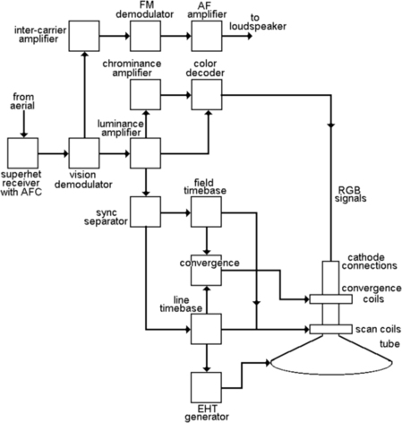 |
| Figure 8.20 A general block diagram for a color receiver. The convergence circuits keep the individual electron beams aimed at their respective phosphor stripes. Without convergence corrections, the picture is satisfactory only at the middle of the screen |
A pulse is taken from the line timebase and used to switch on gates, circuits that will pass signal only for a specified interval. One of these gates allows the color-synchronizing ‘burst’ to pass to the local sub-carrier oscillator to maintain it at the correct frequency and phase. This oscillator output is fed to a demodulator whose other input is the modulated sub-carrier, and this has the effect of recovering the V signal. The oscillator output is also phase shifted through 90° and this shifted wave is used in another demodulator to recover the U signal. The U, V, and Y (monochrome) signals are then mixed to get the R, G, and B signals that are fed to the CRT guns.
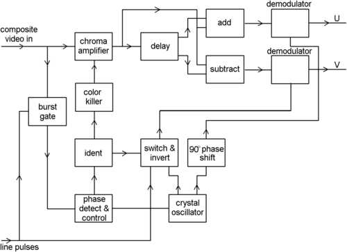
That is the simplest possible outline, and it is quite close to the original NTSC system for receivers. The PAL receiver incorporates more complications because at the camera end the V signal was inverted on each line, and the receiver needs to be able to combine the V signals from each pair of lines by storing the information of each line and combining it with the following line.
This is done using the block diagram of Figure 8.21, which shows part of the PAL receiver concerned with color decoding. One output from the crystal oscillator is passed to an inverter circuit, and this in turn is controlled by a bistable switch. The word bistable, in this context, means that the switch will flip over each time it receives a pulse input, and its pulse inputs are from the line timebase of the receiver, so that the switch is operated on each line. The action of the switch on the inverter will ensure that the oscillator signal is in phase on one line and will reverse (180° phase shift) on the next line, and so on. Also shown in this diagram is an arrangement for an identification (
ident) signal, taken from the burst signal, that makes certain that the bistable switch is itself operating in phase, and not inverting a signal that ought to be unchanged.
 |
| Figure 8.21 The decoding of the PAL type of signal. This is a very complicated process compared with the older NTSC system |
The sub-carrier signals are fed to a time delay. This is arranged to delay the signal by exactly the time of one line, and the conventional method originally was to use a glass block. The electrical signals were converted into ultrasonic soundwave signals, and they traveled through the glass to a pickup where they were converted back into electrical signals. The delay is the time that these ultrasound signals take to travel through the glass block, and the dimensions of the glass are adjusted so that this is exactly the time of a line. More modern receivers used electronic digital delay circuits, using the principle of the shift register (see Chapter 11).
The delayed signal (the sub-carrier for the previous line) is added to the input signal (the sub-carrier for the current line) in one circuit and subtracted in a second circuit so as to produce averaged signals for the U and V demodulators that will contain no phase errors. Note that averaging by itself would not correct phase changes; it is the combination of averaging with the phase reversal of the V signals that ensures the correction.
In addition, there are embellishments on the circuits, and one of these is the color
killer. When the transmitted signals are in monochrome, any signal at the sub-carrier frequency would produce color effects at the receiver, so that these circuits must be switched off for transmissions (old films, for example) that contain no color. This is done by using the color burst signals, so that when a color burst is present, a steady voltage from a demodulator will ensure that the color circuits are biased on and working. In the absence of the burst signal, the color circuits are biased off, ensuring that any frequencies around 4.33
MHz (the color sub-carrier frequency for the UK) in the picture signal do not cause colors to appear.
Summary
Summary
The color processing for an analog receiver consists of separating off the signals at the sub-carrier frequency. A copy of the sub-carrier is generated and its phase and frequency are corrected by the burst signal. This sub-carrier can be used in demodulators to recover the original U and V color difference signals, and these can be combined with the luminance signal to form separate R, G, and B color signals. For the PAL system, the sub-carrier used for the V signal must be inverted on every other line, and an ident signal is used to ensure that the inversions are in step. In addition, the color signals are passed through a time delay of exactly the time of one line, so that the color signals of one line can be combined with those of the previous line (with the V signal inverted) to provide averaged U and V signals.
We will look at the digital television systems that have completely replaced the analog system in Chapter 16.
..................Content has been hidden....................
You can't read the all page of ebook, please click here login for view all page.