
Chapter 7. Disc and Tape Recording
Historical outline of sound recording from Edison and Berliner systems. Electrical methods for shellac disc recording. Development of vinyl discs. Compression and equalizing systems. Hi-Fi and stereo. Loudspeakers - woofers and tweeters. Stereo balance. Historical evolution of tape recording. Tape and cassette recording. Tape as a non-linear medium. Ultrasonic bias for tape recording. Development of cinema sound. Sound tracks on movie film. Variable width and variable brightness optical analog recording systems. Photocell as a replay transducer. Magnetic recording systems for movies. Modern digital optical systems. Home cinema setup. Problem of noise on recordings. Noise reduction system for analog recording. Dolby and dbx. Companders. Analog video recording. AMPEX and helical scan techniques. Domestic videotape made obsolescent by DVD and hard-drive systems.
Note
Most of this chapter is now of historical interest because of the immense impact of digital methods on sound recording. Nevertheless, it is important to understand why the switch to digital was made, and this is possible only if you know what the problems of analog were (and still are) and how they have been dealt with. In addition, there is a vast number of analog recorders still around, and they shall quite certainly need repairs and maintenance for years to come.
Early Gramophones
The first gramophones were totally mechanical. The sound that was being recorded was caught in a metal horn and used to vibrate a membrane at the narrow end of the horn. The vibrating membrane, in turn, moved a sharp stylus vertically on a revolving wax cylinder, driven by clockwork. This type of recording is known as ‘hill and dale’, and was also used on flat discs. To replay, the stylus was moved back to the start of the track, and the wax cylinder or disc was rotated again. This was the basis of the Edison Phonograph, and the wax cylinders that were cut for these machines are now treasured antiques.
Wax cylinders were fragile and difficult to mass produce, and the system was later applied to wax discs cut laterally so as to make a wavy groove, a system pioneered by Emile Berliner, who was producing these discs in 1892. The discs had the considerable advantage of being easier to store and pack than the cylinders and they also avoided the problem of the stylus jumping from one peak of a hill and dale recording to the next. The discs could easily be reproduced by electroplating and pressing to make shellac discs with the same imprint of a wave. Playing a record was simply the reverse of this process, spinning the shellac disc at a steady speed, eventually standardized as 78 revolutions per minute (r.p.m.), and picking up the sound using a needle in the groove whose movement vibrated a membrane at the end of a horn. Gramophones like this featured in many households in later Victorian times and were still in production, particularly in portable form, in the 1930s. Edison's original idea of 1877 and Berliner's improvements had a long working life.
The use of tubes for amplification promised to solve one of the problems of the acoustic gramophone, which was the lack of any effective volume control. You could always reduce the volume by stuffing a few socks down the horn, but increasing it was out of the question, though a few inventors harnessed compressed air to make amplifying horns. The main focus for improvements, however, was the recording process. Trying to get a full orchestra around a brass horn was difficult, and no form of control was possible. The possibility of using more than one microphone, being able to control treble and bass response with filters and to ensure that the record tracks did not overlap (through overloading) spurred the development of electrical recording methods. By the early 1930s, virtually all records were being made using electrical methods and the systems that were developed also contributed to the addition of sound to silent films in the late 1920s.
Electrical Methods
Figure 7.1 shows a typical electrical recording system, and this block diagram is applicable right up to the time when compact discs (CDs) started to replace the older vinyl long-playing (LP) records. In the block diagram, several microphones are shown connected to a mixer, so that some control can be obtained, allowing the sound balance of a soloist and of different sections of a band or an orchestra to be achieved. This type of system also makes it possible to reduce background noise, like the coughs and sneezes of an audience, to some extent. The mixer stage is followed by amplification and then by filtering (of the lowest and highest notes) and compression stages (to avoid overcutting), then by a driver (a power amplifier). The signals from the driver operate the cutter head which, as the name suggests, cuts a track in the master disc, which can be metal, wax, or plastic. The power that is needed for a good-quality cutter can be very large, and in the latter days of LP discs cutter-heads might require up to 1
kW of power.
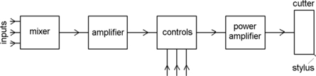 |
| Figure 7.1 Principles of disc recording. The signals from different microphones are mixed together, amplified and filtered (using potentiometer controls), and applied to a power amplifier that drives the cutter head. This cuts a master disc which is then used to produce other masters for pressing copies in vinyl plastic |
The compression stages need some explanation. A sound source such as an orchestra has an immense range of amplitude (typically 100
dB or more) from its softest to its loudest, and this range simply cannot be recorded on to a disc (or a tape). Taking the disc example, the softest sounds leave so little trace that only the noise of the needle on the disc can be heard on replay. The loudest sounds overdrive the cutter so that the waves on one part of the track overlap and break into an adjacent part of the track, making the record unplayable. The solution is to decrease the range, boosting the amplitude of the softest sounds and reducing the amplitude of the loudest, and this is the action called
compression. In addition, even if the range of amplitudes is fairly small, the treble has to be boosted because most of the noise of a disc is in the form of a high-pitched hiss which would otherwise drown out the highest notes of music, and the bass has to be reduced because it is more likely to cause track overlapping.
The record player then has to reverse these processes, boosting the bass frequencies (typically in the range 30–120
Hz) and reducing the treble (typically in the range 4–10
kHz), and this process, called
equalizing or
equalization, is possible only if electronic methods are used; you cannot use old socks (or even new ones) for this task. In addition to equalizing, variable controls for treble and bass are needed to adjust the sound to compensate for the size, shape, and furnishing of the room in which it is heard. Figure 7.2 shows a block diagram for a record player of good quality with separate bass and treble controls. The signal is obtained from a pickup, another type of transducer which is similar in construction to a microphone, but using the vibrations from a stylus on the record groove rather than from a membrane.
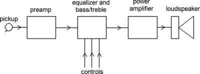 |
| Figure 7.2 Disc replay. The feeble signals (often less than 1
mV amplitude) from the pickup are amplified, and then equalized. At this stage, tone and volume controls can be used. The power amplifier then provides the drive for the loudspeaker |
Any pickup that is of reasonable quality suffers from the disadvantage that its output is a very small signal, in the region of a few millivolts at most, so that a fair amount of amplification is needed. The equalization, volume, bass and treble controls have to be applied at a stage where the amplitude of the signals is reasonably large, a volt or so, and the final portion is power amplification to drive a loudspeaker. This block diagram is, once again, one that has remained much the same from the 1930s to the 1980s, because the change from the older shellac 78 r.p.m. record to the 33
1/3 r.p.m. long-playing vinyl disc required no change in the basic methods for a single channel (mono) signal. As for radio, changing first from tubes to transistors and then to integrated circuits (ICs) made no difference to what was being done, only to the details of how it was achieved.
Summary
Summary
The system of disc recording pioneered by Berliner used a groove cut in a shellac (or later, vinyl) disc and modulated by the sound waves. For good-quality recording, the bass amplitude must be reduced and the treble frequencies boosted on recording and the opposite actions carried out on replay. Electrical recording and reproduction offers much more control over the process and has been used almost universally since the 1930s.
Hi-Fi and Stereo
In the late 1940s the word ‘hi-fi’, an abbreviation of ‘high fidelity’, burst in from the USA, and brought new life to the old gramophone. The spirit of hi-fi was that the sound which you heard at home should be as good as it was in the studio or concert hall. The ideal of perfection was always unattainable, but the principle was good: the quality of most gramophones at that time was abysmal, as bad as the quality we now put up from small transistor radios and from loudspeakers in almost every shop (with a few honorable exceptions). The nearest anyone ever got to reasonable quality at that time was in some cinemas (when they played music from a disc before or after the film) and better sound was a feature of the original version of Disney's
Fantasia (1940), which could at that time be shown in full glory only in the very few cinemas that were equipped for stereo sound.
Hi-fi in these days required large loudspeakers (
woofers) that could faithfully reproduce the bass notes, along with small ones (
tweeters) to do justice to the higher notes. It also required good pickups, good preamplifiers, separate treble and bass controls and, above all, an excellent power amplifier stage. All of these requirements could be satisfied by good designs using tubes, and the amplifier that set the standard in the 1950s for the UK was the Leak, with its (then) remarkable figure of less than 0.1% distortion. In these days, home construction was popular, and many firms that became well known started with a home-made system which then was put into quantity production. Some of the amplifiers of that time are now valuable collectors' items, even the kit models that were sold for home assembly.
Hi-fi was about sound quality, and quality cannot be indicated in a block diagram, so that what we have seen in Figure 7.2 still holds. The development of stereo sound, however, made some changes. The principle was not new, and the idea of supplying each ear with a slightly different sound pattern had been established as long ago as the start of the twentieth century. Stereo creates an impression that the sound is no longer coming from one small space, and all the first listeners to stereo talked about a ‘feeling of space’, a ‘broad band of music’, and so on. What was lacking in the early days, however, was any way of achieving stereo sound on a standard gramophone disc, though the principle that was eventually adopted was based on one patented in 1936 by A.D. Blumlein (whose list of patents covers almost everything we think of as modern electronics).
Disc stereo recording uses a cutting head whose stylus can be vibrated in two directions that are at right angles to each other, cutting tracks in the walls of the groove. With the signals from two separate (left and right) microphones used to control the currents, one wall of the groove contains a left track and the other a right track (Figure 7.3). Replay also uses a single stylus that is connected to two pickup elements, each sensing movement in one of two directions at right angles, so that the outputs are of left and right signals. A movement along one axis has no effect on the axis that is at right angles to it, so that there should be no interference between the signals.
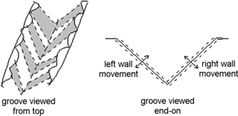 |
| Figure 7.3 Stereo disc recording principles. The walls of the groove are at 90° to each other, and they are separately modulated with L or R signals The principle is that two mechanical motions at 90° to each other do not interfere with each other, so a pickup can detect L and R signals that are quite separate |
The stereo gramophone block diagram looks as in Figure 7.4, with separate L and R signals from the pickup passing through their own independent amplifier chains. Each channel (L or R) has treble and bass controls, and these are normally ganged (meaning that they are potentiometers that use the same spindle so that they rotate together). The volume controls can be separate, but it is more usual to gang them also and use an additional
balance control to set the ratio of left to right volume. The balance control is normally set so that the main sound appears to come from between the two loudspeakers that are arranged one to the left and one to the right of the listener(s).
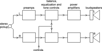 |
| Figure 7.4 A block diagram for a stereo disc replay system. This consist of two separate amplifiers, sharing a power supply, and with volume and tone controls ganged so as to operate together. There must also be a balance control to allow for loudspeaker positioning and other factors that may bias the sound to one side or the other |
The coming of stereo caused a momentary halt in the hi-fi process, because listeners were more impressed by stereo of any kind than by high-quality single-channel sound (and this has not changed appreciably over the years). Another factor that has limited the appeal of high-quality sound has been the emergence of pundits who have brought to sound reproduction the flowery words and the mystique of wine tasting (but often with little justification). The plain truth is that it is easier now to achieve good-quality sound than it has ever been in the past, and without elaborate and costly equipment. Achieving the best possible quality is, as always, quite another matter, and if money is no object you can obtain really superb reproduction; but the outcome is often quite utterly disproportional to the cost, as you may have to redesign (or construct) the room in which you listen to cut out unwanted echoes and other disturbances.
Summary
Summary
The popularity of hi-fi as a hobby in the late 1940s led to an interest in better standards of reproduction, boosted by the vinyl LP record and the use of stereo recording. Hi-fi required good pickups, well-manufactured records, good amplifiers, and good loudspeakers, and though the transition from tubes to transistors (and to ICs) was slower than it was for other branches of electronics, it eventually happened. Vacuum tube amplifiers are, however, still available because some listeners prefer a distorted sound from a tube amplifier to a less distorted sound from a modern IC and transistor amplifier.
Tape and Cassette
We often think of magnetic tape recording as comparatively new, but it was invented by the Danish engineer Valdemar Poulsen (1869–1942) in 1889, and a (wire) recording that was made in 1900 by Emperor Franz Josef of Austria–Hungary has survived. The principle (Figure 7.5) is simple enough. A ring of magnetic material, with a coil of wire wound round it, will be magnetized when current flows in the coil. If there is a small gap in the rim, then the magnetization around this gap will be very strong, and when the current through the coil is alternating current (AC), the magnetization around the gap will also alternate in direction and strength. This concentrated magnetic field will affect any magnetic material near it.
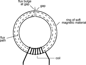 |
| Figure 7.5 A primitive tape-head in detail. The alternating current through the coil causes a strong alternating magnetic field at the gap which will magnetize any magnetic material that is in contact with the gap |
Sound is converted, using a microphone, into electrical signals, and these are connected to the coil. A magnetic material, which originally was a steel wire, is drawn past the magnetic core at a steady speed, so that each portion of the wire will be magnetized to a different extent, depending on how much current was flowing in the coils when that portion of wire was drawn past the core. To replay this, the process is reversed, connecting the coil to headphones. As the wire is drawn past the core, the changing magnetism causes currents to be created in the coil and these are heard as sounds in the headphones.
Poulsen's Telegraphone, as he called it, worked and was easier to use than a disc recorder with less risk of damage to a recording (unless you waved a magnet near it), but it never became a home item, unlike Edison's Phonograph (which used wax cylinders) and the later Berliner (flat disc) machines. The ability to record was not something that was important for entertainment in the days before radio, but the main point that made the wire recorder unattractive for the home was the need to use headphones: only one person could hear the faint recorded sounds, whereas the sound from a disc recording could ‘fill a room with the full, rich notes’ from its horn (the description dates from 1897). Poulsen's invention was used to a limited extent as an office dictating machine up to the 1920s but it was superseded for a considerable time by disc-based recorders.
The principle never totally died out, however, and radio companies experimented with wire recorders as a way of preserving important performances. The recording companies also took an interest, because recordings on wire could be edited, unlike recordings made on wax discs, and by using enough wire, a recording lasting twenty minutes or more could be captured. This was a significant advantage, because a wax disc could hold only about five minutes of recording. The limitations caused by the use of wire, however, were difficult to deal with, and these old recorders used (literally) miles of wire moving at high speed across the magnet core or
recording head.
The rebirth of magnetic recording occurred in Germany during the 1939–1945 war. The BASF company, famous for aniline dyes, developed plastic tape with a magnetic iron-oxide coating that was immensely superior to iron or steel wire for recording uses, and could be used at much lower speeds of around 15 inches per second. Tape recorders of advanced design were found when the Allies invaded Germany, and were passed to electronics companies in the UK and USA for inspection. As a result, tape recorders became commercially available in the 1950s. In this respect, electronics firms were more commercially aware than the British motor industry, which was offered free manufacturing rights on the Volkswagen Beetle, but rejected it on the grounds that such a curious vehicle could not possibly be a commercial proposition. The outcome of that decision has been that VW now owns a large chunk of the former British motor industry, including Bentley (and BMW owns Rolls-Royce).
The record companies and radio companies were delighted with these developments in recording, and they started a demand, which still exists, for high-quality tape equipment. Apart from the editing convenience, the use of tape allowed for stereo recording (by using two tracks recorded on the tape) at a time when this was very difficult to achieve on disc, and also for sound effects that had not been possible earlier (produced, for example, in the BBC Radiophonics workshop, famous for its ‘Dr. Who’ theme). The use of tape recorders at this level fed down and resulted in an interest in sound recording at home.
Figure 7.6 shows a typical block diagram for a domestic tape recorder. The tape-head is a refined version of the coil and core arrangement, using a tiny gap in a magnetic metal to form a concentrated magnetic field across which the tape is moved during recording. The same head is used for replaying, and a switch allows the head to be connected to the record or replay circuits. On professional tape recorders separate heads are used for writing and for reading. These blocks contain familiar portions, but the bias/erase oscillator block requires some explanation.
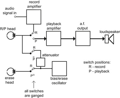 |
| Figure 7.6 A block diagram for a tape recorder, showing the record/replay switching. As is normal, the same head is used for both recording and replay, though better results can be obtained by using three separate heads (record, erase, and replay) |
One important problem for magnetic recording is that magnetic tape is not a linear medium: a graph of recording current through the coil of the recording head plotted against the stored magnetism is not a straight line, more like an ‘
S’ shape, with no retained magnetism at all for small currents (Figure 7.7). This makes the replayed sound appear impossibly distorted, even for speech. Early on, this had been tackled by adding a permanent magnet near the head, which improved matters but not to such an extent that tape could be considered good enough for recording music. The problem was solved by adding a
bias wave at a high frequency (too high for the human ear to detect) of around 50–100
kHz. When this is done, using an amplitude that has to be carefully set for the type of tape and the tape speed, the results can be acceptable. With meticulous adjustment and good circuit design, tape recording could be good enough for making the master recordings for gramophone records, and was used in this way from the 1940s onwards. Making the quality acceptable on home recorders which had to be produced at a reasonable price was another matter.
Note
Note
The upper limit of the range of frequencies that can be recorded is affected by the tape speed and the head gap. Achieving a good response for high frequencies demands either a very small head gap (a gap of 0.001 inches is an enormous gap!) or fast tape speeds. The other problem is noise, because the nature of magnetism makes tape a noisy medium. Noise is less of a worry on wide tape, but the trend has been to use narrower tape, often with four tracks so that the track widths are very narrow.
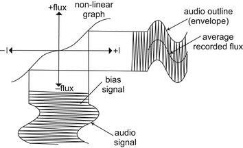 |
| Figure 7.7 The effect of bias with a high-frequency signal is to overcome to some extent the non-linear shape of the graph of magnetization plotted against signal strength |
As it happened, the novelty for home recording on tape wore off, mainly because the tape, contained on open reels, had to be threaded into the recorder, and because there was little demand for recordings on tape to match the range and variety of gramophone discs. A whole generation of low-cost open-reel tape recorders was eventually scrapped when Philips invented and marketed the compact cassette in 1961. The principle is the same and so the block diagram is the same, but what has improved is convenience.
Cassettes originally offered low-quality sound, using narrow tape used at a low speed, and the original intention was to use the machines as dictaphones. The convenience of the cassette, however, led to recorders being marketed both for home recording and for replaying prerecorded cassettes, and in the following twenty years remarkable strides were made in improving tape, methods, and mechanisms until it was possible in the 1980s to claim with justification that cassette tapes could be used as part of a hi-fi system. The introduction of digital audio tape (DAT) made no impression on compact cassette sales, and all recordings that were available on other media (vinyl disc or CD) were at that time also available on compact cassette. A miniature form of recordable CD, called the Minidisc (MD), was available at one time but has now passed into history.
Summary
Summary
Tape and cassette recording of sound is not new, but the methods that are used to make the sound of acceptable quality are of recent origin. All magnetic recording makes use of a magnetic material being moved past a recording/replay head which consists of a metal core with a narrow gap and a coil of wire, and the construction of this head is very exacting if good-quality recording is required. Though open-reel tape recording is obsolete for domestic use, cassettes became a standardized and accepted way of distributing recorded music and their use has not completely vanished even now that CD and MP3 are the standard audio formats.
Cinema Sound
In the twentieth century, no electronic system before television made such an impression as cinema sound, films with a sound track, in 1928. The successful system, called Phonofilm, was invented by Lee De Forest, who had also invented the first amplifying radio vacuum tube, and the principles did not change until the use of magnetic tape tracks in more recent times. Early systems had suffered from inadequate volume and from synchronization problems, but De Forest solved both problems by using the film itself to record the sound and by making use of tubes for amplification.
The block diagrams for a cinema sound system of the traditional type (now almost obsolete) are illustrated in Figure 7.8. On recording, the sounds are converted into electrical signals using microphones, and mixing is carried out as required. The amplified signal is used to drive a ‘light-valve’, which opens or closes according to the amplitude of the signal wave at its input. These light-valves were originally electromagnetic, though other principles have been used. By placing the light-valve near the edge of the film, illuminated by a light beam, a strip of otherwise unused film can be exposed to light that is controlled by the light-valve, creating a wave pattern on this strip of film, the sound track.
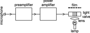 |
| Figure 7.8 Recording cinema sound, using the film to carry the sound track. This depends critically on the design of the light-valve |
Since these early days, two separate principles have been used. One used the light-valve to vary the
width of the light beam (variable-width system) that reached the film, while the other used the valve to control the
brightness of the light (variable-density system). Whichever method was used on recording, the developed and printed film contained a strip of sound track (Figure 7.9) situated between the frame edge and the sprocket holes. This strip of film has been exposed so that it contains a picture of the sound in the form of variations of either width or of blackness (Figure 7.10).
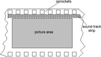 |
| Figure 7.9 Location of the sound track on a 35
mm film |
 |
| Figure 7.10 Variable width and variable density sound tracks compared. The replay system will cope with either type of track |
This sound track can be played back using a
photocell, a type of transducer that responds to light either by generating a voltage or by allowing current to pass from a voltage supply. On playback, the light of the cinema projector hits the sound track as well as the main frames of the film, so that as the film moves the amount of light passing through the sound track to the photocell varies, generating a variable voltage or current which is an electrical signal that can be amplified (Figure 7.11). The same playback system can be used whether the film uses variable-width or variable-density sound recording.
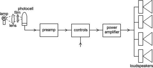 |
| Figure 7.11 The replay arrangement uses a photocell whose (feeble) output signal is amplified. Cinema sound requires large amplifiers to provide power to a bank of loudspeakers spaced around the cinema |
Incidentally, the sound track that corresponds to any particular frame of a file is not placed next to that frame. This is because film in a projector or camera does not run smoothly but in jumps. Each frame is held for about 1/24 second for exposure and then moved rapidly, and this would put a loud 24
Hz hum on to the sound track if we read the sound track at the point of projection of the frame. Instead, the sound track is placed about 30 frames ahead of the picture at a point where the film is moving steadily rather than in jumps. This solves the hum problem, but it makes editing more complicated than it was for silent films, and it also causes problems if a film breaks and has to be repaired by taking some frames out, because the sound track that is removed does not then match the removed picture.
Magnetic recording, using a magnetic stripe on the edge of the film (preceded by a system in which a reel of magnetic tape was wound alongside the film), was used between 1952 and 1999. This was eventually abandoned because the magnetic stripe was vulnerable to wear and tear to a much greater extent than an optical track. At the time of writing several types of digital recording exist using optical recording and most films are released with several types of optical tracks and the older analog optical track as well. Digital tracks are recorded on the side of the film opposite the analog tracks, and also in the spaces between sprocket holes. Several versions of optical digital recording are due to the well-known recording specialist, the Dolby Laboratories.
Home Cinema
The availability of large-screen television receivers has triggered a market for home cinema for watching high-definition television or Blu-ray recordings (see later) along with multichannel sound. The familiar part of the equipment has to be a large-screen television receiver, usually a plasma type rather than liquid crystal display (LCD), and set up for high definition (HD) as well as standard definition. A Blu-ray disc player (which can also play the older type of DVD) forms an essential part of the video package. For sound, a ‘surround-sound’ system is needed using at least five loudspeakers (front left and right, rear left and right, and a sub-woofer, for very loud low-pitch unmusical sounds such as explosions, which can be placed centrally). A controller/amplifier is also needed for this setup so that the audio signals from the television signal or Blu-ray player can be allocated to the correct loudspeakers.
The results, like the prices, can very enormously, but even the low-cost systems can provide an enjoyable way of watching movie films at home. As for all sound systems, however, the domestic arrangements (furniture, curtains, carpets) can have a considerable effect on the sound, so that real enthusiasts will set aside a room as a cinema room, with acoustics that enhance the experience. It is possible to spend as much as it might cost you to visit your local commercial cinema nightly for several years.
Noise
Noise is one of the persistent problems for any type of recorded sound, as we have indicated already. A really old recording on shellac disc will consist so much of hissing and scraping that you wonder how anyone could listen to it with any enjoyment, and though the noise level of discs had been reduced by the 1940s it was the main factor in the popularity of the long-playing vinyl disc which replaced the older type. The lower speed of the LP, along with the use of a long-life diamond or sapphire stylus and equalization circuits, kept the noise level of the LP reasonably low, and this seemed satisfactory until we heard (or didn't hear) the noise level of CDs.
The noise level on early cassette tapes almost rivaled that of the old discs. Tape noise is always a problem, and it was dealt with to some extent on professional equipment by using wide tape moving at high speed. The width of a cassette tape allocated for four tracks (two in each direction) is only 1/8 inch, whereas an open-reel machine will use at worst two tracks on 1/4 inch tape, or use much wider tape such as the 1/2 inch type (now used for video) or more. In addition, the frequency range that can be recorded on tape is very limited when the tape speed is low. Cassette tape moves slowly, at about 1 7/8 inches per second (i.p.s.) rather than the 15
i.p.s. or 30
i.p.s. of professional tape equipment, and this can restrict the highest frequencies that can be replayed to as low as 6
kHz or less. This inability to record or replay the higher frequencies is also controlled by the width of the gap in the tape-head, and a large gap means one-thousandth of an inch. Tape-head gaps are usually stated in micrometers, with 1
μm being a thousandth of a millimeter.
Noise Reduction
Development of better tape materials has greatly improved the noise performance of tape, and we can now make tape-heads with gaps that are in the region of 1–10
μm. Even with all that, however, tape could not be considered suitable for serious use without noise-reduction circuitry. Several schemes have been used in the past, but the only ones that have survived have used equalization methods, deliberately altering the signals before recording and reversing the action on replay. The best known of these noise-reduction systems is Dolby, named after the British engineer Ray Dolby (who at one time also worked in the development of video recording at Ampex Inc.). The Dolby B noise-reduction system is almost universally used for prerecorded cassettes, and other versions such as C or HX Pro are used on more expensive equipment. There was also another system,
dbx, which was astonishingly effective, but had some drawbacks that prevented commercial success.
Figure 7.12 illustrates the Dolby principle. Tape noise is at a low amplitude and it is concentrated in the higher frequencies. The amplitude of the noise, however, is almost the same as the amplitude of the softest music, and the hiss that you hear when you turn up the volume to hear better is very noticeable because the human ear is particularly sensitive to this range of frequencies. In addition to the noise problem, tape will overload if too large an amplitude of signal is recorded.
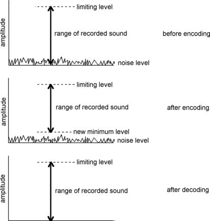 |
| Figure 7.12 Noise reduction on cassette recorders. The sound signals are processed so as to reduce the range, in particular to ensure that no signals fall to a level as low as that of the noise. When the signal together with noise is expanded, the noise almost disappears |
On recording, the Dolby circuits split the electrical signal into separate channels. The lower frequency signals pass unchanged. The low-amplitude signals in the higher frequency range are boosted, making their amplitude greater than they were in the original signal. On the C and HX Pro systems, signals that have an amplitude that would cause overloading are reduced, so the result is a signal whose smallest amplitudes are still above the noise level and whose maximum amplitude does not overload the tape. When the Dolby recorded tape is replayed, the processing that has been carried out on recording is reversed.
The attenuation of the signals that have been boosted will also reduce the noise signals from the tape so that they are almost undetectable and if the more advanced systems have been used, the tape will also deliver sound that has a much greater range (from softest to loudest) than is possible when no processing has been used. Though the C and HX Pro systems offer better noise reduction, the Dolby B system is almost universal on prerecorded cassettes because it does not alter the sound too much. This means that if you replay a Dolby B recording on a player that is not equipped with Dolby decoding the sound does not sound distorted, just a little biased to treble. This is not something that could be said for the other systems (though undecoded dbx can be acceptable in a noisy car because the volume is almost constant).
Note
Note
These noise-reduction systems are often referred to as
companders, because the amplitude range is compressed when the recording is made and expanded again when the sound is replayed.
Because of Dolby, cassette tapes can be used as part of a serious hi-fi system, and cassette tapes that have been recorded using systems such as Dolby C or HX Pro can almost rival a CD for low noise, though not for sound amplitude range. Dolby noise reduction is also used extensively in cinema sound, nowadays as a digital–optical system.
Note
Summary
Note
Noise and noise-reduction systems have now become much less important with the adoption of digital methods (such as CD) for sound recording other than for cinema.
Summary
Noise is the enemy of all recording and broadcasting systems. Tape noise is particularly objectionable because it consists of a hiss, a type of sound to which human ears are particularly sensitive. For professional recording, the use of wide tape overcomes the problem to a considerable extent because a wider tape has a larger magnetized area and so produces a larger signal that ‘swamps’ the noise. The narrow tape used on cassettes, however, has a high noise level that cannot be overcome completely by using better tape materials. Noise-reduction systems operate on the principle of selectively boosting the amplitude of the recorded sound when it is recorded and decreasing it on replay, and a particularly effective method of doing this concentrates the boosting and reducing actions on the frequency range that is most affected.
Video and Digital Recording
The recording of sound on tape presented difficulties enough, and at one time the recording of video signals with a bandwidth of up to 5.5
MHz, and of digital sound, would have appeared to be totally impossible. The main problem is the speed of the tape. For high-quality sound recording, a tape speed of 15
i.p.s. was once regarded as the absolute minimum that could be used for a bandwidth of 30
Hz to about 15
kHz. Improvements in tape and recording head technology made it possible to achieve this bandwidth with speeds of around 1
i.p.s., but there is still a large gap between this performance and what is required for video or for digital sound recording. This amounts to requiring a speed increase of some 300 times the speed required for audio recording. Early video recorders in the 1950s used tape speeds as high as 360
i.p.s. along with very large reels of tape.
Analog video recording, even now, does not cope with the full bandwidth of a video signal, and various methods of coding the signal are used to reduce the bandwidth that is required. In addition, the luminance (black and white) video signals are frequency-modulated on to a carrier, and the color signals that are already in this form have their carrier frequency shifted (see Chapter 8 for more details of luminance and color signals).
For domestic video recorders, the maximum bandwidth requirement can be decreased to about 3
MHz without making the picture quality unacceptable, but the main problem that had to be solved was how to achieve a tape speed that would accommodate even this reduced bandwidth. In fact, the frequency of the carrier ranges between 3.8 and 4.8
MHz as it is frequency-modulated to avoid the problems of uneven amplitude when such high frequencies are recorded on tape.
The brilliant solution evolved by Alexander Poniatoff (founder of the Ampex corporation) was to move the recording head across the tape rather than move the tape over a head. Two (now often four) heads are used, located on the surface of a revolving drum, and the tape is wound round this drum so that the heads follow a slanting path (a
helical scan) from one edge of the tape to the other (Figure 7.13). The signal is switched from head to head so that it is always applied to the head that is in contact with the tape. At a drum rotation speed of around 1500 rotations per second, this is equivalent to moving the tape past a head at about 5 meters per second.
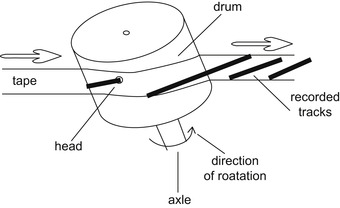 |
| Figure 7.13 Principle of rotary-head video recording. The two (or more) heads are mounted on a drum, and the tape is wrapped at a slight angle. This makes the head trace out a sloping track across the tape as the drum revolves and the tape is pulled around it at a slow rate |
Though the way that the head and the tape are moved is very different from that used for the older tape recorders, the principles of analog video recording remain unchanged. The block diagram for a video cassette recorder is very different from that of a sound recorder of the older type, but the differences are due to the signal processing that is needed on the video signals rather than to differences in recording principles.
Note
Note
Videotape is, at the time of writing, almost obsolete (as attested by the huge stacks of videotapes in charity shops) and has been superseded by digital versatile disc (DVD), the digital system that uses the same principles as CD. This is particularly suited to digital television signals, and in the UK has been used mainly for players of unnecessarily expensive discs (it costs less to press out a DVD than to record a tape). DVD recorders with a recordable and reusable disc are readily available and of good performance, and another answer to the need for domestic recording and replay has been to use a computer hard drive (magnetic disc) along with conversion circuits so that ordinary analog television signals (as well as digital signals) can be recorded digitally.
These hard drive units have typically a capacity of up to 45 hours, so that a single unit can cope with most domestic recording needs. With the switch to digital television in the UK complete in 2011 the use of hard-drive video recorders will be almost universal. A particular advantage of these hard-drive recorders is that (using buffer stages) they can record and replay simultaneously, so that when the unit is switched on it is possible to view a live program, place on hold while answering a telephone call or having a meal, and resume viewing later. The facility is available also for digital radios in the areas where reception is possible. Ideally, we might have a hard-drive recorder along with a DVD recorder so that really useful recordings could be preserved.
Later sound recorders (before the extensive use of CD recorders) for very high-quality applications used
digital audio tape (DAT). This operated by converting the sound into digital codes (see Chapter 9) and recording these (wide-band) signals on to tape using a helical scan such as is used on video recorders. The main problem connected with DAT is that the recordings are too perfect. On earlier equipment, successive recording (making a copy or a copy of a copy) results in noticeable degradation of the sound quality, but such copying with DAT equipment causes no detectable degradation even after hundreds of successive copies. This would make it easy to copy and distribute music taken from CDs, and the record manufacturers succeeded in preventing this misuse of DAT (though not in the Far East). DAT recorders that were sold in the UK were therefore fitted with circuits that limited the number of copies that could be made, and the DAT system disappeared when recordable CDs and, later, DVDs were developed.
Summary
Summary
Tape as a recording medium hardly seems adequate for sound recording, and its use for video and for digital sound has been a triumph of technical development. As so often happens, however, the relentless progress of technology has made tape-based systems obsolescent just as they seemed to have reached their pinnacle of perfection.
..................Content has been hidden....................
You can't read the all page of ebook, please click here login for view all page.