Chapter 14. Computers and Peripherals
State machines. Computer essentials. Block diagram for simple computer. Address decoder. ROM unit. RAM unit. UART chip. PIO chip. Hard drive. Operating system. Peripherals connected to the computer. Modems. Amplitude-shift keying (ASK) and frequency-shift keying (FSK).Phase-shift keying (PSK) and Multi-phase PSK. Dial-up modem principles. Broadband principles. ADSL. Discrete Multi-tone (DMT) system. Modem-Router. Broadband over cellphone. Monitor (VDU). Graphics card. Analog monitor. Graphics processor. Driver programs. Sound card. Active loudspeakers. Printers. Centronics and USB connections. Paper feeding methods. Inkjet printer principles. Bubblejet and piezoelectric principles. All-in-one printers with scanner built in. Laser printer. Toner. Monochrome and color laser printers. Scanner. Optical character recognition (OCR).
Definition
A computer is a programmable microprocessor system with a large amount of random access memory (RAM), a keyboard and a visual display unit (VDU) as minimum requirements. Data in binary form can represent denary numbers, words, pictures, or sound. The actions of the computer are made possible by the programs that it can run. For general-purpose use a computer needs an operating system (see Chapter 15). A
peripheral is a device that is connected to a computer to perform such actions as display, printing, selection of operations, communication, etc.
Note
The computer is just one example of a class of devices that are known as
state machines. A state machine is anything that can store information, change information, and cause a signal or action output.
Computers
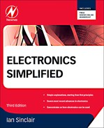
Figure 14.1 shows a block diagram for a generalized 8-bit data computer system which would have been typical of small computers in the early 1980s, and whose principles can still be applied to modern 32-bit machines. The block that is labeled MPU is the microprocessor unit, which will have its own internal buses.
Note
Note
The MPU is shown as placing signals on the address bus, because in a system like this with only one processor, the MPU has total control over the address bus; all other chips
receive address signals. The data connection between the data bus and the MPU is two-way, because the MPU must read data as an input and also output processed data. The connection of the MPU to the control bus is also two-way, because the MPU will issue some control signals to other chips and also receive signals from other chips. Note that read-only memory (ROM) sends data to the data bus but does not receive data.
 |
| Figure 14.1 A block diagram for an 8-bit computer, typical of types produced in the mid-1980s. Modern machines are much more elaborate, but the block diagram is typical of basic design |
The address
decoder is the chip that allocates addresses. Some MPU address numbers must correspond to storage in ROM and some to storage in RAM, and a few are reserved for the UART (universal asynchronous receiver/transmitter; serial) and PIO (programmed input/output; parallel) chips. The address decoder chip receives signals from the address bus and from the control bus (originating in the MPU) and determines which of the four memory-using sections will be enabled. This chip prevents any possibility of contention for the use of the buses, because only the chip that is entitled to use the buses will be enabled.
The
ROM unit (usually one or two chips) receives signals from the address bus, and is enabled or disabled by an output from the address decoder. It is also controlled by control bus signals, and its output is placed on the data bus. This output will for the most part be program instructions to the MPU, such as start-up instructions, and short routines for such tasks as peripheral control (disk, VDU, keyboard, etc.).
The
RAM unit (which may consist of a large number of individual chips, each storing one bit of data) uses the signals from the address bus, and is enabled by the address decoder. It also receives signals from the control bus, notably the read/write signals that determine the direction of data flow, and it has a bidirectional (two-way) connection with the data bus.
The
UART chip uses the address bus signals and an enabling signal from the address decoder. It has a bidirectional connection with the data bus and also with the control bus. The control bus can determine the direction of data and can also interrupt the MPU to ensure that serial input is dealt with by a suitable routine. Two separate lines allow for external connections to RS-232 connectors for serial input and output.
The
PIO chip uses the same scheme of address bus connection and enabling line from the address decoder. It has a bidirectional connection with the data bus and also with the control bus, so that it also can send signals to the MPU to interrupt it and run an input routine if required. This chip also has the parallel input/output (I/O) connections to the parallel port connector. Though the PIO is usually operated with a printer as an output only, it can be used by other units bidirectionally, making it possible to connect scanners and disk drive units through the parallel connector.
All of the computer actions are determined by the software, and a computer without software is no more useful than a record player without records. A small amount of software is permanently fixed into the ROM of the computer system, and this can be used to allow a few keyboard actions and, more importantly, to allow more software to be read into the memory from a magnetic disk, the
hard drive (or from a large memory chip in place of a mechanical drive). This software is the
operating system, which consists of a set of routines for using other programs, allowing all the effects that we take for granted. See Chapter 15 for more about operating systems. Operating systems and applications software, and the details of constructing computer systems, are outside the scope of this book, but if you are interested, take a look at my book
Build and Upgrade Your Own PC (currently in its fourth edition). There are also many websites that will instruct you in the art of computer assembly.
Note
Summary
Note
Microprocessors and computing methods are used in many applications that are not quite so obvious. The engine management system of a modern car is a microprocessor-based computer system that takes inputs such as engine speed, air temperature, throttle opening, and so on to control fuel injection and ignition timing. Automatic gearbox systems are similarly controlled and integrated with engine management. Even the humble washing machine or dishwasher is now certain to use a microprocessor system to replace the old methods based on electric clock mechanisms with cams and switches.
Summary
Calculators and computers use a microprocessor as the main programmable unit. Calculators generally use only a number keyboard and a number display, with a small memory. Computers use a much wider range of connections such as hard and floppy drives, compact disc (CD) units, sound boards, scanners, light pens, full-sized keyboards, and cathode-ray tube (CRT) monitors.
Peripherals
Modem
Definition
The word modem is derived from the words
modulation and
demodulation, and is used for a device that allows computer data to be passed along telephone lines or by radio links. A telephone line was never intended for more than voice signals, so that it operates best with frequencies in the range of 300–400
Hz. By contrast, computer signals consist of successive 0 and 1 voltage levels which may be at a speed of many megahertz.
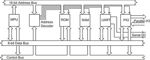
Clearly, it is impossible to transfer unaltered computer signals along an ordinary telephone cable. To achieve communication of data along telephone lines the data rate must be reduced, and some form of modulation must be used. This is the basis of the modulation action of the modem, and a block diagram of how the modem is used to link computers is illustrated in Figure 14.2.
Definition
Definition
Any sinewave carrier can be modulated in three different ways, by modulating its amplitude, its frequency, or its phase. This gives rise to the different methods that are used in modems, called amplitude shift keying, frequency shift keying, and phase shift keying. Combinations of keying methods are possible.
 |
| Figure 14.2 Using modems to allow computers to communicate by telephone lines. This is the basis of electronic mail and the Internet |
The
amplitude shift keying (ASK) system alters the amplitude of the carrier according to the level of the data signal. At its simplest, the carrier can simply be switched on for logic 1 and off for logic 0 (this is also known as on–off keying or OOK). This type of modulation has fallen out of use because of its poor signal-to-noise (S/N) ratio and therefore its high bit error rates. The problem is that ASK signals and noise signals are very similar, so that a receiver cannot distinguish genuine signals from noise signals.
A
frequency shift keying (FSK) system involves switching the carrier wave between two frequencies. In the 1970s, small computers used one form of this, known as Kansas City (or CUTS) modulation, for tape-recording digital signals, and this form is a good example of the method. For the CUTS standard bursts of eight cycles of 2400
Hz or four cycles of 1200
Hz are used to represent 1 or 0, respectively. FSK systems for modems have used other frequency values, often with a frequency ratio that is not exactly 2:1. FSK has a better bit error rate than ASK under the same conditions, but requires a wider transmission bandwidth.
Phase shift keying (PSK) is a method that is now the most commonly used for low-speed modems. This uses a single carrier frequency whose phase is altered by the data signal. For example, a logic 0 might cause no phase change, but a logic 1 will shift the carrier phase by 180°. Of the three methods, PSK has by far the best lowest bit error rate, and the bandwidth that it requires is least.
A more modern development of PSK is
multiphase PSK, in which the carrier phase can be shifted to several different values. For example, if eight different values of phase can be used, then each digital signal represented by a phase change can consist of 3 bits (since a 3-bit signal can convey number values of 0 to 7, eight in all). If phase and amplitude modulation are combined, it is possible to carry 4 or more bits of digital data per unit carrier. Such systems are also used for the NICAM stereo sound system and for digital television (see later).
This allows a carrier of, say, 350
Hz to convey much more information than might be expected, and bit rates of 28,000 per second or more are normal. The effective bit rate can be increased by using data compression (eliminating redundant bits in signals) and by using faster rates along with error detecting and correcting methods. Older modems for small computers were designed to input information at 56,000 bits per second and output at a lower rate (because modems are used in small computers mainly to read in data, with very little being passed outwards). Modems are now used to link computers (using the Internet) that can be located anywhere in the world, and pass information over any distance.
The traditional type of modem for many years was the dial-up type, but around 2000 broadband began to take root in the USA (the UK date was around 2002). Broadband overcomes two serious limitations of the dial-up system, one of which is that it ties up the telephone line so that when the modem is in use the telephone cannot be used. The other disadvantage is the limited speed of the dial-up modem. Using broadband, speeds of up to 8 megabits per second are possible if you live reasonably close to a telephone exchange, and much higher speeds are possible if your telephone is supplied by fiberoptic cable.
Dial-up principles
In practice, a modem is connected to the serial port of the computer, or plugged in to the bus lines. Software is used to set up the modem and the port for the required data rate, the telephone number to use, and so on. When a communication is to be sent, the software will make the modem open the line and dial the number, and when the remote computer answers, the two confirm connection and the data is sent. At the other end, the modem has responded to the ringing tone and has opened the line. The signals from the transmitting modem are analyzed, the receiving modem automatically sets itself to use the same system. It then acknowledges contact, and receives the signals, which are usually stored as a file on the disk. The modem can be located inside the computer or externally.
Note
Summary
Note
If you use the dial-up system with just one telephone line to your house, you cannot use the telephone at the same time as you use the Internet. At one time, some users would install two telephone lines, keeping one for voice calls and the other for the Internet. With broadband, you can use both together.
Summary
The dial-up modem (modulator–demodulator) is used to connect computers over telephone lines. A low-frequency carrier is modulated by the digital signals from a low-speed serial port. By using suitable modulation systems, rates of 9600 bits per second and higher can be achieved with a very low error rate. Modern software allows the modem to be controlled very easily, and enables actions such as automatic dialing and answering. The use of broadband has superseded dial-up now for most users.
Broadband principles
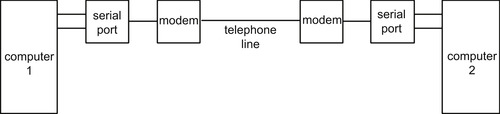
Broadband works by using separate frequency ranges over the telephone lines. The lowest frequencies are used exclusively for telephone conversations. The higher frequencies are reserved for broadband signals, and at each telephone socket you need to use a microfilter that separates the frequencies. The microfilter plugs into the phone socket, and your telephone plugs into the telephone socket on the microfilter. Your computer is connected (by way of a modem or, more usually, a modem–router) to the other outlet on the microfilter. The system that is used for domestic broadband is called ADSL (asymmetric digital subscriber line), and the asymmetric part refers to the rates: fast for downloading data to your computer, but slow for uploading from your computer to a website (since you need downloading much more than uploading). The arrangement of frequency bands is illustrated in Figure 14.3.
Note
Note
Broadband can also be used over other metal lines, such as power lines.
 |
| Figure 14.3 The arrangement of frequency bands for broadband |
The predominant system for modulation in the UK is called
DMT (
discrete multitone). As the name suggests, the available bandwidth for ADSL is used by a set of sub-carriers that are spaced 4.3125
kHz apart. Each of these sub-carriers will be modulated by a portion of the digital data, and sub-carriers that are not required will be suppressed so as to save total bandwidth. This approach is similar in principle to the methods used for digital radio, and the usual digital processing methods are used to ensure high efficiency and signal integrity.
Given then that you can get the modulated broadband signals from the microfilter, what then? You could use a broadband modem, but most users nowadays go one step further and install a
modem–
router. As the name suggests, the router connects to the broadband socket of the microfilter and passes demodulated data signals to and from one or more computers. The advantage of this is that you can connect more than one computer to the broadband (and to each other), so setting up a home network. In addition, if the router is of the wireless type you have the choice of connecting by way of a WiFi signal as well as by cables.
The most significant advantage, however, is in security. Modems are not truly secure devices, but routers are much better and if you enable the firewall of the router and use the highest level of security for any WiFi connection then you can be reasonably relaxed about security (though Windows users should ensure that they have an effective virus detector such as AVG Free).
Though ADSL through existing telephone lines is the most favored system in the UK at the time of writing, delivering speeds up to 8
Mb/s in areas close to a telephone exchange, it is not the only method of obtaining broadband. In areas that are serviced by cable television (using fiberoptic cable with wired connection to each household) higher speeds and more reliable connection can be achieved. At the time of writing there is a proposal to upgrade all existing telephone lines, starting with a few selected towns, to fiberoptic cables that are laid in the same conduits as the existing copper lines. This should bring much higher speeds (50
Mb/s or more) for these areas, and the hope is that this will be extended over much of the UK.
Another broadband system uses the mobile phone network. The cost may based on the amount of data downloaded each month (ranging from 5
GB upwards) rather than on speed, or a combination of speed (typically 7
Mb/s) and download limit (0.5–5.0
GB typically) can be quoted. The number of providers and options makes it very difficult to decide what is a reasonable deal for any given user. The technology is simple: a universal serial bus (USB) fitting adapter (a
dongle) contains the mobile phone SIMM chip (single in-line memory module; the data chip for the mobile phone) and is plugged in to your computer. All the software supply and setting up are then carried out for you and the security risks are less than for a fixed line system. This type of connection is intended primarily for those who must use the Internet on the move (despite the signal fluctuations from place to place) and the cost makes it less attractive to home users.
The last option is broadband by satellite, using the incoming satellite signals to carry the downloaded data and a fixed telephone line to upload. Prices are comparable to ADSL, with the advantage that the signal can be better in areas that are distant from a telephone exchange. For business users for whom cost is less of a factor, a transmitting satellite dish can be used to provide faster uploading.
Monitor or Visual Display Unit
Definition
The monitor or VDU is the system for displaying an image. Early microcomputers made use of a television receiver, but the need for higher resolution has led to the development of specialized displays which are nowadays always color units.
The conventional older type of monitor uses a CRT or liquid crystal display (LCD) panel to produce a picture that consists of a set of colored points. The
resolution (meaning how much detail can be seen in a picture) can be measured in terms of the number of dots per screen width and depth. Note that a printer achieves much higher resolution than any monitor, measured in terms of dots per inch rather than dots per page width. The equivalent dots per inch for a screen is around 75; the accepted minimum for printers is 300 and many printers achieve 600 dots per inch or more in monochrome (a lower figure for color).
The type of picture that we can show on a monitor depends greatly on how much control we can achieve over the brightness and color of each individual dot on the screen, and this is where the
graphics card becomes important, because when the personal computer (PC) first appeared it could not display any graphics, only text. This required only minimal control, light or dark for the letters and symbols of the alphabet and digits.
The simplest way of controlling the dot brightness on a monitor is simply to turn the dot on or off, so that
on means bright and
off means dark. This scheme was used for monochrome monitors before color pictures became the universal standard, and it was later extended to color displays by using on–off control for each of the primary colors of light, red, green, and blue. Signals that use the three color primaries in this way can produce red, green, and blue using the dots for primary light colors and can also show the mixture of red and green, which is yellow, the mixture of red and blue, which is magenta, and the mixture of blue and green, which is called cyan. The mixture of all three colors is white. Using a simple on–off scheme like this can therefore produce eight colors (counting black and white as colors).
The simple on–off method can be improved by using a fourth on–off signal, called brightness or
luminance, the effect of which is to make the colors brighter when this signal is switched on, so that you have black and gray, red and bright red, and so on, a range of 16 colors including black. This 16-color system was so common in the past that a lot of software still features 16 colors despite using a graphics system that allows a much greater range of colors. A monitor of this type is a digital monitor because its inputs are digital.
Analog monitor
The alternative to these on–off video signals is to use the
analog type of signal that is used for television monitors, in which each signal for a color can take any of a range of sizes or amplitudes, not just on or off. This method allows you to create any color, natural or unnatural, by controlling the brightness of each of the primary colors individually. A monitor like this is much closer to television monitors in design, and some (but certainly not all) monitors of this type can be used to display pictures from sources such as television camcorders and video recorders. Monitors for a modern PC should allow the use of resolutions up to around 1600
×
1200. The color capabilities depend on the number of bits used to code each pixel, and the relationship is that the number of colors that can be displayed is 2
N, where
N is the number of bits per pixel. Twenty-four-bit color is a common requirement for applications such as digital photography, and this corresponds to 16,777,216 colors, usually referred to as 16 million colors. Thirty-bit and 32-bit color systems are also used for critical applications.
Note
Summary
Note
Some older computer monitors are referred to as
digital, but this does not mean that the signals are digital. In this context, digital means that there are no potentiometers used for adjustment of such items as brightness or contrast, only push-button switches (one for increase, one for decrease). This use of the word ‘digital’ has now died out because all monitors now use selection by push-button or menu selection.
Summary
Monitors originally used a digital form of signal, displaying a monochrome picture for text use. Later, a 16-color system was developed by using digital switching of each of the primary colors, plus a brightness signal. All of these display types are now obsolete, but modern monitors can use a digital connection that produces a better picture quality than the analog type of connection. Modern monitors, mostly LCD types unless for very large displays, are capable of high resolution and a full range of color, 24 million colors or more.
Graphics Card
Definition
The signals from a computer cannot be used for a display directly, and a graphics card, plugging into a slot inside the computer, is used to perform this conversion and to produce signals of the correct type and voltage range for a monitor.
Note
Some modern computers have
motherboards that include the circuits of a graphics card, and many also include a sound card.
The original type of PC display was concerned only with text, because the concept of a machine for business use at that time was that text, along with a limited range of additional symbols, was all that was needed for serious use as distinct from games. The original video card was referred to as the
monochrome display adapter, a good summary of its intentions and uses, and usually abbreviated to MDA.
MDA produced an excellent display of text, with each character built up on a 14
×
9 grid. The text was of 80 characters per line and 25 lines per screen, and at a time when many small computers displayed only 40 characters per line using a 9
×
8 grid, this made text on the IBM monitor look notably crisp and clear. Typical monitors used a 18.4
kHz horizontal scan rate and 1000 lines resolution at the center of the screen, and they still look good for a text display.
Graphics pictures could not be displayed using the MDA card, however, so that graphs could not be produced from spreadsheets (on screen at least), and applications such as desk-top publishing (DTP), painting, digital photographic editing, or computer-aided design (CAD) were totally out of the question. As the need for graphics in color grew, various solutions in the form of different graphics cards appeared. The 16-color color graphics adapter (CGA) was used in the mid-1980s, but it was soon replaced, first by the extended graphics adapter (EGA) and then by the video graphics adapter (VGA) cards.
Note
Definition
Note
The VGA standard permits full compatibility with earlier types of display, and it adds displays of 640
×
480 16-color graphics and 720
×
400-color graphics, using a 9
×
16 grid for characters with color. The VGA type of card used nowadays is classed as SVGA (S for super), and it permits much higher resolution (such as 1280
×
1024) and the use of a large number of colors (16 million or more). You should not consider using an older type of graphics card on a modern PC, because some modern programs would not run on an older type of card, and others would provide very disappointing graphics. One particularly useful action of a graphics card is to scale large images to the screen resolution, so that a camera image of around 4000
×
3000 can be displayed on the whole screen of 1280
×
1024.
Definition
All modern graphics cards contain a specialized processor, the
graphics processor, along with chips to support the fast actions that must be performed so that a set of digital data can be transformed into the signals for a color image. A substantial amount of memory is also needed.
The more memory your graphics card can use, the more easily it can work with high-resolution and high-color images, and some graphics cards come with 128
Mbyte or more of their own memory. Others make do with less, and some will grab memory from the computer’s RAM, which is not an ideal situation unless you are using several gigabytes of RAM.
Another point to consider is that it takes time to transfer the large numbers of bytes that images require, so that the speed of a graphics board is important. To achieve faster rates of transfer of bytes, later graphics cards used slots connected so that they could operate at higher speeds. Originally, a slot type termed PCI, operating at 33
MHz, was often used, but faster types such as AGP (66
MHz) replaced it. The most recent type of slot at the time of writing is the PCIe, with the ‘e’ meaning express. This is a very fast serial type of connection with the computer, introduced in 2004, and it is likely to be found on modern computers, albeit in a variety of versions ranging (in order of increasing speed) from PCIe-1 to PCIe 16/2.
The graphics card must also be connected so that it can send signals to the monitor, and the conventional VGA type of connection was designed for CRT analog monitors, though its use continued on LCD monitors. Modern LCD monitors use the digital video interface (DVI) type of connector, though the VGA connection is often provided as well. The two are impossible to mix up because the VGA type uses a 15-pin connector with round pins and the DVI type uses a different pattern of flat pins. Just to add to the confusion, however, these cables come in the legendary 57 varieties, and it is possible to buy a DVI cable and connector that will connect with both analog and digital monitor inputs. As always, you have to specify what graphics card you want to connect to what monitor.
Summary
Definition
Summary
A graphics card is the interface between the computer and the monitor. It contains a processor of its own (a graphics processor), along with support chips and memory, often as much as 4
Gbyte (though only the fastest and most expensive graphics cards can make use of such large memory sizes). You have to specify the correct type of connection to your computer, and the correct type of connection from the graphics card to the monitor.
Definition
A
driver is a program that is used to control the signal output from the computer to a device such as a monitor, printer, mouse, keyboard, or scanner. The PC operating system, typically Windows, provides a set of drivers for the most commonly used graphics cards, and also for several that you are not likely to encounter in the UK.
As always, nothing on a computer works unless there is a program for the action, so that graphics boards need such a program, called a
graphics driver. Each design of graphics board will need to have a driver written for it, and these drivers can often be a source of problems if they interfere with other computer actions.
If you use an operating system other than Windows (such as Linux or Mac) you should make sure that a driver is obtainable before you buy any equipment that needs a driver.
Sound Card
Definition
A sound card (or sound board) is used as a way of allowing the computer to work with digital sound signals, such as the output from a music CD. The sound board contains A/D and D/A converters, so that it allows a microphone or other source of sound signals to be connected as inputs, or headphones or loudspeakers to be used as outputs. The use of the microphone also permits direct voice input software to be run. A sound board is an essential addition if multimedia CD-ROMs are to be used.
Early sound boards or cards used 8-bit single-channel sound coding, and this is too crude for music of reasonable quality, though adequate for speech or sound effects. Later boards all use 16-bit sound, allowing for music to CD standards. In addition, the later boards are two-channel for stereo sound. Such boards can be very elaborate, incorporating specialized chips for manipulating digital sound. Many card types come with software for editing sound files.
The facilities you can expect from any sound board include a CD-ROM drive interface, loudspeaker and amplifier outputs, inputs for microphone (high sensitivity) and for other (stereo) sources (line input, lower sensitivity), a volume control for use when passive loudspeakers are used, a musical instrument digital interface (MIDI; which in some designs can also be used for a joystick), and stereo headphone connections. As usual, the sound card needs a software driver.
Note
Note
Loudspeakers for connecting to a sound card are almost always of the type called
active loudspeakers, which means that they do not rely on the power of signals from the computer. They come with a mains adapter that provides power independent of the computer.
One of the two active loudspeakers contains an amplifier, and has to be connected to the house mains supply. It also sends the amplified signal to the other loudspeaker. The cable connecting the computer to the loudspeakers is usually fitted with miniature jack plugs at either end.
Summary
Summary
The sound card is added to the PC, or it can be incorporated on the main board (motherboard). It provides connectors for input and output of analog or digital sound, along with analog to digital (A/D) and digital to analog (D/A) converters. The loudspeaker output of the sound card is normally used for a pair of active loudspeakers.
Printer
Definition
A printer is an important computer peripheral, a device that is external to the computer and connected through a data cable. The printer allows text or graphics to be printed on paper.
Many types of printer have been marketed for computers, but the dominant varieties are inkjet types and laser printers. The impact dot-matrix printer that was once the only type available is rarely seen nowadays, and the daisywheel (like an electric typewriter) is obsolete. All printers require a considerable amount of processing ability to convert the signals of codes from the computer into marks on paper, so that a printer will always contain a microprocessor and some memory. In addition, power transistors are used for controlling electric motors and other aspects of printing and paper handling.
At one time all printers used the old standard Centronics connector, so that you could use any printer with any computer, provided that software drivers were obtainable. At the time of writing, USB connectors have replaced the old (and bulky) Centronics type. These connectors are illustrated in Figure 14.4. Some printers also use network or radio connections so that they can be operated from more than one computer or at a distance.
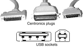 |
| Figure 14.4 Standard Centronics parallel printer connector along with the later USB connection (not to scale) that has replaced Centronics |
Paper feeding is tractor, sheet-feed, or manual. Tractor feed, now used mainly for office equipment, uses paper that is perforated with holes of about 4
mm diameter on the margins so that it can be moved by a pair of wheels that have teeth which engage into the holes of the paper. The margins are lightly perforated for easy removal, and the continuous paper can be separated into separate sheets (burst) by tearing along the divisions. Sheet-feed uses a hopper to carry the paper, usually 50 sheets or more, and each sheet is fed on demand into the printer. Manual feed requires you to insert each sheet by hand and prompt the printer to work on it. By convention, tractor feed paper is used mainly in US sizes, but sheet-feed normally uses A4 in the UK. Sheet-feed is almost universal on printers intended for home use, but several printers cater for inserting single sheets or cards even when the main feed is from a hopper.
Inkjet printer
Definition
The inkjet printer uses a matrix principle, with a line of tiny jets used to squirt a fast-drying ink at the paper. A line of dots is placed on the paper and the inkhead then moves a fraction of a millimeter across the paper to deposit the next line of dots. This process is repeated until the entire shape of a letter is printed. The two main systems currently are the bubblejet and the piezoelectric jet. Both need power transistors to actuate the printing of each dot.
The bubblejet system, devised by Canon, uses a tiny heating element in each jet tube, and an electric current passing through this element will momentarily vaporize the ink, creating a bubble that expels a drop of ink through the jet. The piezoelectric system, devised by Epson for its Stylus™ models, uses for part of the tube a piezoelectric crystal material which contracts when an electrical voltage is applied, so expelling a drop of ink from the jet. This latter system has been developed to allow for high-resolution printing of 720 dots per inch or more, and bubblejet models of high resolution are also available.
Both types of inkjet can print in color (using colored inks in addition to black), with resolution of 600 dots per inch or more, and at speeds of, typically, 12 pages per minute of text. Color printing is always much slower than monochrome. Inkjet printers are cheap, but the manufacturers recover their investment by charging very high prices for the ink cartridges. Combination inkjet printer/scanner machines (often referred to as all-in-one) can be used as copiers.
Laser printer
Definition
The laser printer has become the standard office printer on the grounds of high-speed printing and quiet operation. The principle is totally different from that of inkjet printers, and is much closer to the photocopier principle, based on xerography.
The heart of a laser printer is a drum which is wider than the width of the paper the machine will use and made from light-sensitive material. This drum is an insulator, so that it can be electrically charged, but the electric charge will leak away in places where the drum has been struck by light. The principle of the laser printer (and the photocopier) is to charge the drum completely and then make the drum conductive in selected parts by being struck by a laser beam. The beam is switched on or off and scanned across the drum as the drum rotates, all controlled by the pattern of signals held in the memory of the printer, and enough memory must be present to store information for a complete page. A schematic for a typical laser printer is shown in Figure 14.5.
 |
| Figure 14.5 The outline of a monochrome laser printer |
This system requires about 0.5
Mbyte of memory as a minimum for text work, and 2
Mbyte or more if elaborate high-resolution graphics patterns have to be printed. Color laser printers can use typically 64
MB maximum. Once the scanning process is complete, the drum will contain on its surface an electrical voltage ‘image’ corresponding exactly to the pattern that exists in the memory, which in turn corresponds to the pattern of black dots that will make up the image. Finely powdered resin, the
toner, will now be coated over the drum and will stick to it only where the electric charge is large, i.e. at each black dot of the original image.
Note
Note
Color laser printers are obtainable, and are no longer costly. The cartridges are very expensive, but they have a very long life compared to the inkjet cartridges (typically, my black cartridge is replaced once a year and the color ones every three years) so that maintenance costs compare well with inkjets. However, it may be cheaper to replace the printer rather than buy a complete set of replacement cartridges, because the cartridges are very large and elaborate compared with inkjet types. Another point is that you can operate a laser printer for years without problems, whereas inkjet types tend to suffer from blocked jets and, once again, it is cheaper to buy a new inkjet printer than to replace the jet heads. Hewlett-Packard printers have combined ink-tanks and jetheads, so that the heads are replaced as well as the ink. This is more costly than replacing an ink-tank, but it avoids the problem of having to replace a set of blocked heads.
The coating process is done by using another roller, the
developing cylinder, which is in contact with the
toner powder, a form of dry ink. The toner is a light dry powder which is a non-conductor and also magnetic (some machines use a separate magnetic developer powder), and the developing cylinder is magnetized to ensure that it will be coated with toner as it revolves in contact with the toner from the cartridge. A scraper blade ensures that the coating is even. As the developing cylinder rolls close to the main drum, toner will be attracted across where the drum is electrically charged, relying on the electrical attraction being stronger than the magnetic attraction. Note that two forms of attraction, electrostatic and magnetic, are being used here.
Rolling a sheet of paper over the drum will now pass the toner to the paper, using a corona discharge to attract the toner particles to the paper by placing a positive charge on to the paper. After the toner has been transferred, the charge on the paper has to be neutralized to prevent the paper from remaining wrapped round the drum, and this is done by the static-eliminator blade. This leaves the toner only very loosely adhering to the paper, and it needs to be fixed permanently into place by passing the paper between hot rollers which melt the toner into the paper, giving the glossy appearance that is the mark of a good laser printer. The drum is then cleared of any residual toner by a sweeping blade, recharged, and made ready for the next page.
The main consumables of this process are the toner and the drum. The toner for laser printers is contained in a replaceable cartridge, avoiding the need to decant this very fine powder from one container to another. The resin is comparatively harmless, but all fine powders are a risk to the lungs and also carry a risk of explosion. Drum replacement will, on average, be needed after each 80,000 copies, and less major maintenance after every 20,000 copies. Paper costs can be low because any paper that is suitable for copier use can be used; there is little advantage in using expensive paper, and some heavy-grade paper may cause problems of sticking in the rollers.
Some models use a separate developer powder (a set of negatively charged and magnetic beads) in addition to toner, and the developer will have to be replenished at some time when the toner is also exhausted. The Hewlett-Packard LaserJet machines use a cartridge which contains both the photoconductive drum and the toner in one package, avoiding the need for separate renewal. The life is typically quoted at about 3500 sides at the average print density of word-processed text, but this figure will be drastically reduced if you print a lot of dense graphics and fonts. Long-life cartridges are available.
Note
Note
Summary
Note
A monochrome printer of any type cannot reproduce true continuous-tone photographs, because each dot that it prints is black. The effect can be simulated by mixing black dots and white spaces, a process known as half-toning, but this leads to a coarse appearance on a 300 dot per inch printer and is really satisfactory only on a typesetting machine which works at 1200–2400 dots per inch. Note also that the heating element (fuser) used in a laser printer will cause problems of bubbling with glossy paper (such as is used for printing photos on inkjets). Color laser printers will give a glossy finish on plain papers and the very glossy type should be avoided.
Note
All printers can work with ordinary office paper provided it is not too thick. In some printers, particularly color laser printers, the path of the paper through the printer is so tortuous that only relatively thin paper can be used, so that printing items such as business cards cannot be done. A few printers feature a straight paper path, and this is very much better if you are likely to want to use thicker material.
Summary
Printers for small computers are either inkjet or laser types. Inkjet printers are very versatile, and are well suited to digital photographic work as well as for normal text printing. Laser printers are more appropriate when a large volume of printing work is required. Whatever type of printer you use, a suitable software driver must be installed in the computer.
Scanner
Definition
A scanner is a device that reads documents by using an image sensor strip, and stores a digitized image as a file. This can be used as a form of copier, for editing graphics, for fax transmissions, or for reading text into a word-processor without retyping. Scanners can be handheld, flatbed or roller-feed types, though flatbed types are by now the most common and the others are seldom offered for sale. More recently, combined scanner/printer units have become popular.
Note
Scanners are connected to the computer nowadays by way of the USB socket, which has replaced a variety of older connectors. Whatever method is used, driver software will have to be installed before the scanner can be used. Some scanners (such as the Canon LIDE series) need no separate mains cable because they can use the 5
V supply that comes from the computer through the USB cable.
The item to be scanned can be any mixture of text and images on paper, and modern flatbed scanners all work in color, usually 24-bit. A cold-cathode light source in the shape of a tube is moved over the document, and the reflected light is sensed by a set of photosensitive dot-sized cells, each of which contributes one pixel of the image. The speed of movement is controlled by a servomotor, and resolution can be increased by reducing the speed of movement and by making more than one pass over the document with a small displacement from the original position. Low-power scanners use a light bar of tiny light-emitting diodes (LEDs) that require much lower power than the old-style light tube.
For scanning images, the scanner can be controlled from within any modern graphics program, such as
Paint Shop Pro or
GIMP, and the resulting digitized image can be stored, transmitted through the Internet, or printed as required. More specialized software is needed if the words on a page are to be converted into the form of a word-processor file, because the scanned file is a bitmap, whereas a word-processor uses one byte for each character.
Definition
Definition
OCR means
optical character recognition, and refers to software that will recognize the graphics image of a character and convert this into the ASCII (American Standard Code for Information Interchange) code for that character. In other words, OCR allows the scanner to be used as a text reader, providing an input to a word-processor.
OCR software is usually bundled with a scanner, and provides for a very high standard of text recognition, so that only a spell check is usually needed on the text after recognition. Problems can be experienced with very small character sizes, italic text, or tables, or with a document received by fax. You can usually opt to vary the resolution for OCR from 200 dots per inch, suitable for large type sizes, to 400 dots per inch, suitable for smaller text.
A flatbed scanner holds the page steady and scans it, using a system very like the scanner of a photocopier. The quality is excellent, and modern models allow for color scanning at high resolution and 24-bit color. Automatic page feed can be used on some types, which is particularly useful when OCR is being applied to a long document. The cheapest scanners are useful for domestic purposes, but for professional purposes much more expensive and elaborate machines are available.
Summary
Summary
A scanner is a valuable peripheral that allows you to digitize documents that consist of text and/or images. Scanned text can use OCR software to convert it to ASCII text files for a word-processor. Images can be scanned at high resolution and in 24-bit color using modern flatbed scanners.
..................Content has been hidden....................
You can't read the all page of ebook, please click here login for view all page.