Chapter 16. Digital Television and Radio
Compression methods for digital TV and radio.Viterbi coding. TV coding. HD or HD-ready receivers. HDMI cable. 8-bit coding for video. Flash conversion. Multiplexing into packets. Modulating digital TV signals. Cable, Satellite and terrestrial systems for modulation. Signal strength and S/N ratios. Bandwidth. Problem of signal reflections. Ghosting. Cable transmission and QAM type of modulation. 4_QAM or QPSK, QAM-16 and QAM-64. Fiber-optica main cable with metal wiring from main to house. Satellite transmission. Low S/N ratio but large bandwidth. Low-noise block (LNB). Ceramic resonator adjustment of local oscillator. Terrestrial transmission. US and European methods. Freeview. Coded Orthogonal Frequency Division Multiplexing (CODFM). Digital TV receivers. DVD. Digital radio. DAB (Europe) and IBOC (USA) systems. Digital radio reception. Power consumption of digital radio. HD radio. FmeXtra. DRM+. Satellite digital radio. Digital radio by Internet.
Note
Do not read this chapter in isolation. You will need first to have read and understood the material in Chapter 11 and Chapter 12.
Compression
Digital television and audio signals were in use for studio recording and editing well before broadcasting of such signals became possible. In closed circuits, bandwidth is of little consequence, but broadcasting is bound by the existing frequency bands. What made broadcasting of digital television and radio possible was the development of compression methods, and in particular the MPEG standards.
Chapter 12 has already outlined the compression methods that are used, classed either as lossy or non-lossy. Though non-lossy compression is used for digital signals in a closed (studio) network, it cannot provide enough compression for use with broadcast signals for which bandwidth is limited, and the various lossy systems described earlier along with the techniques of interleaving are also used. Error-detection and correction systems are also important for broadcast signals, and in addition to interleaving and Reed–Solomon methods, another advanced error-correcting system called
Viterbi coding is also used.
Note
Note
Lossy compression must not be used on signals that have to be edited, because after several editing and saving actions the effect of the repeated compression might make the picture unusable. All lossy compression is therefore applied just before transmission.
Television Coding
Definition
A digital television signal is created by sampling, either in the camera itself or on an existing analog picture (such as from an analog recording or from a film scanner). The standard digital format allows for either 525- or 625-line pictures, making it easier to exchange information with US systems (though the sound processing is different), and is also designed to be compatible with high-definition television that is now available both from satellite sources and on free-to-air transmissions such as Freeview.
In this book, we will confine most of the descriptions to the older UK 625-line system. High-definition (HD) transmissions can use either 720 or 1080 lines, but the compression that is used can wipe out some of the gain in resolution. Trials of high-definition television (HDTV) started in 2006, and though the initial program output was available on cable and satellite channels only, HDTV on Freeview has been available in some areas since December 2009. Three-dimensional (3D) television is also available in some areas.
A few television receivers have built-in provision for receiving HDTV satellite or Freeview signals, but the vast majority of domestic receivers are at the time of writing only
HD-ready, meaning that they need a set-top box to receive the HD channels (which are separate from the normal channels even if they are showing the same programs). In addition, the HD set-top box has to be connected to the HD-ready receiver using a high-definition multimedia interface (HDMI) cable. The connector for this looks at first sight like a computer USB connector, but they are not compatible. The HDMI connector is also used to connect a Blu-ray player to an HDTV, and this provides a full 1080-line image quality (higher resolution than any broadcast signal).
Getting back to ‘ordinary’ digital television, we might expect from Chapter 8 that the complete analog signal would be sampled and digitized. This, however, is neither necessary nor desirable. For one thing, we do not need sync signals for digital television because synchronization is achieved by clock pulses. The other thing is that the television signal can be divided into luminance (monochrome) and chrominance (color) components. The luminance signal (taking a PAL signal as an example) is sampled at the rate of 13.5
MHz (864 samples in each line), but the chrominance signal is sampled at only 6.75
MHz for each of the two color-difference signals (432 samples in each line, alternately R–Y and B–Y). Using a lower sampling rate for chrominance reduces the data rate and so makes less call on the bandwidth.
Note
Note
The sampling rate used for 525 lines is the same, and the frequency of 13.5
MHz was chosen because it is a multiple of 2.25
MHz, the lowest frequency that is a multiple of both 625- and 525-line frequencies.
Each sample is 8-bit coded (compare this with the 16-bit coding used for sound), and of the possible 256 levels that 8-bit coding can provide, only 220 are used for luminance, with black corresponding to level 16 and peak white corresponding to level 235. The chrominance coding uses 225 levels, with zero signal corresponding to level 128. This allows for coding both positive and negative value of the color difference signals. Levels 0 and 255 are used only for synchronization.
Note
Note
The sampling, using a clock rate of 27
MHz, produces a multiplexed signal, with the form Y-U-Y-V-Y-U-Y-V …, so that each luminance (Y) sample is followed by one of the chrominance (U or V) samples, alternated. The clock synchronizing bits are added at the end of each line, and at the end of each field, and the digitized sound (up to eight stereo channels) can be placed in the line blanking intervals, using about three samples of audio per line blanking interval. The requirement is 3.072 samples per line, so that some lines will use three or fewer, and some will use four.
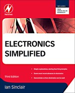
Conversion and sampling are done by an integrated circuit (IC) flash converter. The principle is illustrated in Figure 16.1. A stabilized 2
V supply feeds a chain of 256 (IC) resistors. Each point where two resistors connect is fed to the input of a comparator, for which the other signal input is the analog video signal, set to a maximum amplitude of 2
V. A clock pulse is used to enable the comparators, so that sampling takes place when the clock pulse is high. When the clock pulse occurs, the number of comparators that have an output will depend on the amplitude of the video signal, and this number is converted to an 8-bit code using a multiplexer.
 |
| Figure 16.1 Principles of flash conversion. This is capable of working at very fast clock rates |
The video signal has to be compressed, using a mixture of methods, some of which will be varied depending on the nature of the video signal (for example, static picture or fast motion). The compression is such that six channels of digital video (with sound) can be fitted, by multiplexing, in an 8
MHz carrier bandwidth. The multiplexing scheme is based on the principle of a
packet, as used in optical cable communications systems. Figure 16.2 is a simplified block diagram of the video compression system.
Definition
Definition
A packet is a set of digital signals with an identification word or packet identification number (PID) of 13 bits. Each packet is of fixed length, set for television at 188 bytes (or 204 bytes when Reed–Solomon coding is added), and it carries part of the information for a transmitted program. At a receiver, the packets with the chosen PID can be assembled into a stream of data that constituted the signal for a program.
 |
| Figure 16.2 A simplified block diagram for MPEG video compression |
Once data is in packet form, processes such as interleaving, Reed–Solomon coding, and Viterbi coding/decoding can be used to ensure error-free reception. The remaining problem for broadcasting the signal is how to modulate these packets of digital information on to a carrier, and because the three different methods of broadcasting involve quite different problems, three different methods of modulation are used.
Summary
Summary
Digital television samples the luminance and chrominance information at different rates, using 8-bit samples. These samples are arranged alternately, and compression is used to reduce the amount of data. The compressed data is arranged in packets, so that each of a set of programs can be identified by its PID. The packet data can be interleaved and coded using Reed–Solomon and Viterbi methods to reduce transmission errors.
Broadcasting Systems
Definition
The broadcasting systems used for digital television are the same as were used for analog television, but the method of modulating the digital signals is different for each transmission system. The three main transmission systems are cable, satellite, and terrestrial transmitter. The differences arise because of the problems that are peculiar to each system. In the lifetime of this book transmission over the Internet will probably become a major way of transmitting digital television and radio. Each type of transmission requires a different set-top box (or internal conversion in the television receiver).
Signal strength is an important factor, because if signal strength is low it may be difficult to achieve a good signal-to-noise (S/N) ratio. On an analog signal, a low S/N ratio will cause the received picture to look grainy, and as the S/N becomes worse, the picture will start to break up. For digital signals, the effect is strikingly different. A digital signal is resistant to corruption until the error correction methods can no longer cope, so that the result, as S/N steadily becomes worse, is that the picture remains unaffected until the S/N reaches a critical level, and then breaks up, so that motion looks jerky and images are pixelated (broken into fragments), and ultimately a complete picture appears only at intervals or the screen displays only a still picture. A low S/N also produces a very objectionable noise on sound. For digital signals, the bit error rate (BER) is a more significant figure than the S/N ratio.
Bandwidth is also a determining feature, because the narrower the bandwidth available the more difficult it is to modulate a digital signal. Using a narrow bandwidth increases the time that the data take to transmit from transmitter to receiver, and if the bandwidth is too small the data will not be received rapidly enough to provide a coherent picture.
Reflections are a problem for any transmitted signal, because if the receiver can pick up reflections of a signal, these reflected signals will act like interfering signals because they will not normally be in phase, and if they are reflected from a moving object their phase will change as the reflecting object (such as an aircraft) moves. Reflections cause the familiar ‘ghosting’ effect on an analog signal, so that each part of a picture appears with a ghost image displaced horizontally from the corresponding part of the main image. Reflections in a digital image typically have little effect if the reflected signal is at low amplitude, but they will cause complete break-up if the amplitude exceeds a critical value.
Cable
Cable transmission, using fiberoptic cable for all except the last few meters of the signal path, is by far the easiest from the point of view of signal strength, S/N ratio and reflections. The typical cable bandwidth is up to 8
MHz, the S/N is usually high, and reflections are negligible, so that a transmission method of the quadrature amplitude modulation (QAM) type can be used. As the word
quadrature suggests, it depends on using a two-phase carrier, like the sub-carrier used for chrominance signals in the analog television system.
The two phases can then be modulated independently, and the simplest way to do this is by using each phase to carry one bit, a system called 4-QAM, also called QPSK (see later). With a bandwidth of 8
MHz, however, 4-QAM does not allow the data to be carried rapidly enough, and so each phase of the carrier is modulated at several different amplitude levels. We can use, for example, QAM-16, coding 4 bits for each carrier wave, or we can use QAM-64, coding 6 bits per wave. Using these modulation methods, the data rate can be increased sufficiently to allow successful transmission in the restricted bandwidth.
Note
Note
The cable consists of a main line (trunk) that is usually a fiberoptic type, permitting low-loss operation, with converters to radio frequencies at branches that are used to serve sets of individual houses through coaxial cable.
At the receiving end, the cable is taken to a junction box at each house, and from there a cable is taken to each socket in the house. A set-top box is needed at each receiver to decode the digital signal from the carrier wave and allow selection of the programs from the carrier. Once the digital signals for a program have been extracted, the normal digital receiver methods are used to convert to the analog video and audio signals. In the early stages of conversion to digital broadcasting, the set-top box will convert directly to analog video and audio signals which are connected to an analog receiver by way of the SCART socket. For digital liquid crystal display (LCD) receivers the set-top box is still required for demodulating the signals, but the connection to the receiver can be digital (such as HDMI).
Note
Note
At the time of writing the replacement of old copper telephone lines by fiberoptic cable is planned in the UK. This will allow homes to receive digital television and radio as well as very fast broadband. In cities, cable is already in use, but the replacement of copper by fiber will greatly extend the use of cable for television and broadband.
Satellite
The main problem for any transmission by satellite is the very feeble signal that is received on Earth. This is small enough on the dish size that is used for analog reception, and is smaller still on the tiny digital dish. The main problem, then, for satellite reception is the poor S/N ratio, which can be overcome only if the digital signals are modulated in a way that is very resistant to noise corruption. The compensating advantage is that the microwave frequencies used for satellite transmission allow the use of very large bandwidths, typically 30
MHz or more.
The modulation system that is used is termed quadrature phase-shift keying (QPSK) and, as the name suggests, each of two phases can be modulated with one bit, so that using the two phases (at 90° to each other) allows 2 bits to be carried on each carrier wave or set of carrier waves. This type of modulation is much less likely to suffer corruption by noise than any system that codes a greater number of bits per wave. The current microwave band for digital television satellite broadcasting is in the range around 11.7–12.1
GHz.
At the receiving end, the signal is picked up by a small microwave dish, and converted to a lower frequency, typically to a frequency in the range 950
MHz to 1.75
GHz, by a mixer stage, the
low-noise block (
LNB), located at the dish. This avoids further losses that would be incurred leading a microwave frequency signal down a long cable. The local oscillator in the LNB is set to a fixed 9750
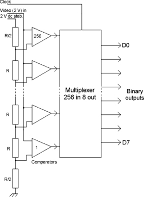
MHz, so that the selection of a carrier frequency is made at the receiver rather than at the dish. Power to the LNB is provided from the receiver or set-top box through the connecting cable. Figure 16.3 shows the typical block diagram for the LNB. This uses special low-noise transistors made from gallium arsenide rather than from silicon, and the layout of the components is very important because even a few millimeters of conductor can have an appreciable inductive reactance at microwave frequencies.
Note
Note
The frequency of the local oscillator in the LNB is usually set by a ceramic resonator (altering capacitance) with a screw adjustment. This is placed close to a portion of the circuit but is not electrically connected other than by stray coupling. Dishes can be fitted with twin, quad, or even octo-LNB units so that several receivers can make use of a single dish (or you can use a twin LNB to supply both the television and a separate recorder that has a satellite input, allowing you to watch one program and record another at the same time).
 |
| Figure 16.3 Block diagram of a typical low-noise block (LNB) for satellite reception |
At the set-top box, this intermediate frequency is converted to a QPSK digital signal, and then through a set of stages that reverse the coding steps that were done at the transmitter end, eventually being converted to analog video and audio signals.
Terrestrial
Terrestrial broadcasting uses the existing land-based transmitters to broadcast a signal directly to existing antennae. The UK version is called Freeview, and it is similar enough to other schemes to serve as an example. If your antenna (aerial) is capable of receiving an analog signal of good quality, then it should be well up to the task of receiving the digital signals on the same range of ultra-high-frequency (UHF) carrier frequencies. A small fortune was at one time being made in ‘Freeview antennae’, but if the antenna signal is adequate for analog there is no reason to change it, certainly not before the Freeview signal is available everywhere. Once the UK changeover is complete in June 2011, all transmitters will be broadcasting Freeview at full power, so that it will be only then that the quality of the digital signal can be assessed.
Once again, the UK has chosen a digital broadcasting system that is different from that used in the USA, so making our television receivers more expensive (as we did by selecting PAL rather than NTSC). The difference is that digital signals for the UK are not modulated directly on to one single carrier frequency.
The system that was chosen for digital receivers and set-top boxes in the UK is called
coded orthogonal frequency division multiplexing (
COFDM). The carrier is coded as if it consisted of a set of 1705 separate carriers, each of 4
kHz, and each modulated, using QAM-64, with part of the digital signal. This makes the transmission rather like a parallel cable with 1705 strands, each strand carrying 6-bit signals. The ICs that code and decode this type of signal are very complex. There was some doubt at the design stage whether the task could be done, and it was for this reason that the 1705 figure was adopted in place of a proposed 8000 carrier system. In fact, the 8000 carrier system could have been used because the technology of manufacturing ICs has progressed just as rapidly as that of the systems using them.
Note
Note
The use of COFDM allows a lower S/N ratio to be tolerated, so that digital transmitters can work on lower power without sacrificing the service area. For example, my local transmitter used during the changeover period power outputs of between 7 and 8
kW (effective radiated power) for BBC and ITV, using channel 49 for BBC and 68 for ITV (and C4). The digital transmitters for the same location work at 7.5
kW for channel 39, but at only 1.5
kW for channel 54 and 1.1
kW for channel 50. Power levels will change when the transition to digital is complete.
At the receiver or set-top box, the COFDM signal is reassembled into a continuous stream of digital bits, and is then decoded for program selection in the same way as is used for satellite or cable reception.
Note
Summary
Note
Even where the normal Freeview signal is strong, there can be momentary interruptions to sound and/or picture. These are much more disturbing than the corresponding faults in analog transmissions and are usually caused by signal echoes. Once the changeover is complete, allowing all transmitters to be run at full power, these problems should ease or disappear.
Summary
Digital television signals can be obtained by using an existing antenna and a suitable tuner (which can be in a set-top box or built in to the television receiver). The other option is to use satellite signals (Sky or Freesat in the UK), mainly through a set-top box, but built in to some receivers. Another option is to use cable if you live in an area that has been cabled. In the future, it will probably be possible to receive digital television and radio through an Internet connection once all the copper cabling has been replaced by optical fiber).
Digital Television Receivers
In a digital television receiver, the tuner contains chips that allow for either satellite signals (from the LNB for Sky or Freesat) or antenna signals for a Freeview receiver to be selected and then decoded to a stream of digital signals. Out of this stream you can select the single program that you want to watch by using the PID (program identity) number that is broadcast with the signal. Selecting the appropriate PID provides the digital signals for one particular program. Because cable transmissions are not available outside cities, no receivers are currently provided with cable reception.
Once this digital stream has been selected, the coding actions are reversed so that the original signals can be retrieved. This set of actions produces an 8-bit luminance signal and two 8-bit chrominance signals together with the digital audio signal. These signals are converted to analog for use in the conventional audio and video sections of the receiver.
DVD
DVD, originally meaning digital video disc, is now taken to mean
digital versatile disc, and it refers to a development of CD technology that is now fully established (and likely to be superseded by Blu-ray; see later). This was originally directed to recording full-length films on CD, hence the ‘video’ in the original title, but the idea has been extended to a universal type of storage disc that can be used for films, audio, or computer data interchangeably. Inevitably, as soon as writable and rewritable DVDs could be manufactured (working along the same principles as CD-R and CD-RW), writing drives became available for computers and are now universally fitted except for the sub-£100 group of notepad computers that are now available.
Note
Note
An important feature of a modern DVD computer or television drive unit is that it will accept conventional CDs as well as DVDs.
The DVD holds much more data, can transfer it more quickly, and is as easy to reproduce by stamping processes as the older CDs. However, by the time DVD became the uniform recording format, replacing cassettes, DAT, videotape, and CD-ROM, it was already close to becoming outdated. In the USA, where Blu-ray discs are relatively cheap, this format has to a considerable extent replaced DVD. In the UK, however, Blu-ray has not taken off as rapidly as was expected.
Film rentals are the main end-use of DVD at present, and video-cassettes are now so out of date that charity shops are flooded with them. Surveys have shown repeatedly that the most common use for video-cassette recorders (VCRs) in the UK is to record television programs either when the viewer is not at home, or when two interesting programs are being broadcast at the same time (yes, it can happen). Though recordable DVD machines are widely available now they have never achieved quite the level of sales that VCRs did, though they offer a much more user-friendly option (no more recording over a show that you wanted to keep, or searching all over a tape to find what you want to see). Even this use of DVD, however, is likely to pass away now that so many set-top boxes incorporate a hard drive (and some also add HD).
For computers, DVD offers so much more storage space than CD that the options it allows are more than most users can cope with at first. A single-layer disc can store 4.7
Gbytes, a large chunk of data, corresponding to just over two hours of digital video signals at a higher quality than is possible using VCR (which relies on considerable bandwidth reduction). More than one layer of CD recording can be placed on a disc, however, because the layers are transparent, and by altering the focus of the reading laser, it is not technically difficult to read either of two superimposed layers that are only a fraction of a millimeter apart.
By making two-layer DVDs the recording time can be doubled, and by adding double-sided recording it can be doubled again to eight hours of video. The discs can contain up to eight audio tracks, each using up to eight channels, so that films can contain soundtracks in more than one language, and cater for surround-sound systems.
The DVD can also end the concept of a film as a single story, because unlike tape it can switch from one set of tracks to another very quickly, allowing films to be recorded with several optional endings, for example. Shots taken using different camera angles can also be selected by the viewer from the set recorded on the disc, and displays of text, in more than one language, can be used for audio and video tracks. Like CD and so unlike VCR, winding and rewinding are obsolete concepts, and a DVD can be searched at a very high speed that seems instantaneous compared to VCR. The disc is also smaller than a video-cassette, does not wear out from being played many times, and resists damage from magnets or heat.
Note
Summary
Note
DVD for video uses MPEG-2 coding and decoding. Even MPEG-2, however, is a lossy compression method, and this sometimes shows in video quality as shimmering, fuzzy detail, and other effects.
Summary
DVD is a development of CD, capable of using both sides (and possibly two layers per side) so as to increase the storage capacity, together with a short-wavelength laser to allow tighter packing of data. This allows for several hours of compressed video to be stored on a disc. Writable and rewritable DVDs are available at low prices both for video recording and for computer data storage.
Digital Radio
We have seen from this and earlier chapters how analog sound signals can be sampled and converted into a stream of digital bits, together with the coding and interleaving methods that can be used to avoid errors on replay. The CD was the first digital sound consumer product, and the enormous developments that have taken place in compression methods since then make more modern systems such as MP3 and digital radio possible.
Note
Note
There is no single system for digital radio, and the world seems to have divided into two regions, one mainly in European and Commonwealth countries, using a system called digital audio broadcasting (DAB), and the other (in the USA) using the in-band on-channel (IBOC) system on FM frequencies, HD on other frequencies, and also digital satellite radio. At the time of writing, 30 or so countries are committed to DAB, and many are testing or committed to IBOC.
Digital radio, unlike digital television, does not offer much to anyone who is satisfied with the existing system. If you have good FM reception of your favorite stations at home, then a change to digital will make a large difference to your bank account but very little change to your ears. Inevitably, the FM broadcasts will be closed down in the UK, because the UK Government has sold the rights to these frequencies in advance to the mobile phone companies (they can help in extending the mobile phone network by making less use of landlines for long-distance hops). It seems at the time of writing that some FM frequencies will remain in use, particularly for local radio.
There has been a lot of questionable advertising for digital radio, claiming better sound, but since the sound (for most of the digital radios on offer) comes from a small loudspeaker it is hardly likely to be any better than an FM radio with the same size of loudspeaker. If pressed, the advertisers will admit that they are comparing digital radio with medium-wave broadcasts (now that everyone listens to FM). Audio devotees, who are likely to spend several thousands of pounds on loudspeakers alone, reject the idea of digital radios being superior to FM, mainly because of the effects of compression.
The most serious problem is that of reception areas. Digital radio broadcasting in the UK uses part of the old band III television frequencies, 217.5–230
MHz, and the coverage for these frequencies was originally plotted for the old ITV signals, for which everyone used an outside rooftop antenna. Today's digital portable radios use a whip antenna, and the signal strength is considerably less than that of an external yagi. Not surprisingly, reception for digital is patchy, and this is not exactly endearing for consumers who find that they can receive their favorite station only if the radio is placed on an upstairs bedroom window-ledge. US listeners, by contrast, can receive digital radio by IBOC or by satellite.
Note
Note
One other problem that has plagued portable DAB radios is power consumption. Older DAB radios had a very short battery life because of the power-hungry DAB chip. Modern units have reduced the power demand, but the chips need around 4.5
W of power, so that many DAB portables use very small loudspeakers (hence the poor sound quality of so many). The best compromise seems to be a power-efficient chip combined with a lithium-ion battery.
At one time, the main advantage was seen to be for users of car radios, because at present if you want to listen to a national station on FM, you have to retune several times in the course of a long journey (though the present generation of FM car receivers can do the retuning automatically). Digital radio, in theory, obviates the need to retune, because all the transmitters for one national station can use the same frequency rather than the different frequencies used at present to prevent one station interfering with another. In practice, as one observer has noted, the main use for digital radio in a car is to find where a usable digital signal might be found.
This has not prevented the government leaning on car manufacturers (who know what customers prefer) to install digital radios in all new cars. The time scale that has been mentioned for the UK is 2015, with the assumption that 50% of all radios will be digital by 2013. At the time of writing, in-car radios that use DAB have FM tuners also, and will switch automatically to FM when (not if) there is no adequate digital radio signal. Digital radio can be received on some motorways and near cities, but reception is patchy over large areas of countryside, and since there is not likely to be a massive program of building new transmitters it looks as if the 50% target will remain a dream for many years to come.
The signals themselves use the same COFDM type of system as was described for Freeview television, but with 1536 carriers for each channel. This allows for multiplexing several signals on to a single data stream. One particular advantage is that the COFDM system is so resistant to interference from distant transmitters that one central carrier frequency can be used for several transmitters (for national broadcasts), ending the misery of trying to listen to a national station going in and out of tune in a moving car. Once coverage has extended to 90% of the country (as has been assumed in various surveys) this ambition can be realized, but it still leaves questions, such as what will be done to listeners in areas where the DAB signal is just about adequate for the BBC channels but no others?
IBOC
IBOC is a digital radio broadcasting system that makes use of the sidebands of FM (or even AM) transmissions to send out digital signals. This has arisen particularly in the USA because the higher frequencies that are used for DAB in Europe are not available in the USA. There are three varieties of IBOC, of which only one, HD Radio, is at the time of writing approved for use. The other two versions are FMeXtra and DRM+, which differ in the way that the additional digital transmissions are modulated on to existing FM or AM carriers.
The take-up for IBOC by radio listeners has not been spectacular. One estimate has put it as low as 1%, compared with the 30% of UK listeners who can and do receive DAB.
Satellite Digital Radio
Satellite broadcasters around the world include radio channels as well as television channels, and set-top boxes for satellite reception usually have audio output sockets that can be used to link them to audio equipment. Sound quality can be excellent (though this depends on the source of the signals). Dedicated satellite radio receivers are rare in Europe but are much more common in the USA, where there has been a strong take-up of digital satellite receivers in cars.
..................Content has been hidden....................
You can't read the all page of ebook, please click here login for view all page.