
Chapter 4
Preamp Architecture
The purpose of this chapter is to look at how phono amplifier stages fit into the architecture of a complete preamplifier that can handle a variety of input source types.
Passive Preamplifiers
Some sort of preamplifier or control unit is required in all hi-fi systems, even if its only function is to select the source and set the volume. You could even argue that the source-selection switch could be done away with, if you are prepared to plug and unplug connectors, leaving a “preamplifier” that basically consists solely of a volume- control potentiometer in a box.
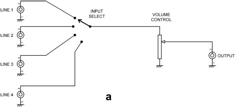
I am assuming here that a selector switch will be required, and that gives us the “passive preamplifier” (oxymoron alert!) in Figure 4.1a.
There is of course no such thing as a passive phono preamplifier; even with high output MM cartridges at least 35 dB of gain is required to get a signal level that can be reasonably applied to a power amplifier. If a passive preamplifier is used then the phono amplifier must be an external active unit with its own power supply. All the amplification is external to the passive preamp, so the outboard phono unit must have a high enough output to drive a power amplifier fully without any further help. This implies that the phono preamplifier must have variable or switchable gain, or its overload margin will be impracticably small.
While a passive preamplifier may have only one component, it does not follow that it is easy to design, even though the only parameter to decide is the resistance of the volume pot. Any bit of gear that embodies its internal contradictions in its very name needs to be treated with caution. The pot resistance of a “passive preamplifier” cannot be too high because the output impedance, maximal at one-quarter the track resistance when volume is set to −6 dB, will cause an HF roll-off in conjunction with the connecting cable capacitance. It also makes life difficult for those designing RF filters on the inputs of the equipment being driven.
On the other hand, if the volume pot resistance is too low the source equipment will suffer excessive loading, and this includes an external phono unit.
If, however, we can assume that our source equipment has a reasonable drive capability, we can use a 10 kΩ pot. Its maximum output impedance (at −6 dB) will then be 2.5 kΩ. The capacitance of most audio cable is 50–150 pF/metre, so with a 2.5 kΩ source impedance and 100 pF/metre cable, a maximum length of 5 metres is permissible before the HF loss hits the magic figure of −0.1 dB at 20 kHz. A very rapid survey of current “passive preamplifiers” confirms that 10 kΩ seems to be the most popular value for the pot. This value will cause no trouble at all for any competently designed opamp-based phono unit but might embarrass a discrete design if the output stage is ill-conceived. It is very unwise to design for an external load that is lighter than 2 kΩ. It is always necessary to avoid unbuffered filter stages at the output of the phono unit, as even a 10 kΩ load is likely to severely degrade their accuracy.
Transformer Preamplifiers
At the time of writing there are at least nine passive preamplifiers on the market that control volume by changing the taps on the secondary of a transformer. These are sometimes called “passive magnetic preamplifiers”. Examples include the Luxman AT3000, the Audio Tekne 9701, and the DaVinci Audio Labs Grandezza. While such amplifiers can give voltage gain by using the transformer to step up the signal voltage, they are still regarded as passive preamplifiers because they have no active electronics and do not require a power supply.
The load on the external phono unit is the power amplifier input impedance reflected from the secondary winding of the transformer to the primary. If the gain is set to unity, i.e. a 1:1 transformer ratio, the input impedance of the power amplifier being driven appears unaltered at the preamplifier input and will load the phono unit. If however the transformer preamplifier is set for a gain of +6 dB, the input impedance will be a quarter of that and may be approaching our figure of 2 kΩ. It is important to remember that while the voltage gain is proportional to the turns ratio, the impedance transformation is proportional to the turns ratio squared, as both voltage and current are transformed. In general preamplifiers are more often set to attenuate rather than amplify, and in this case the preamplifier input impedance will be higher than the power amplifier input impedance, and it is unlikely that an excessive load will be placed on the external phono unit.

There are several potential problems with the transformer approach—they are well known to fall much further short of being an ideal component than most electronic parts do. They can introduce frequency response irregularities, LF distortion, and hum. They are relatively heavy and expensive, and the need for a large number of taps on the secondary puts the price up further. The multiway switch to select the desired tap will be expensive if there are a reasonable number of steps.
There are however some advantages. The output impedance of a resistive potential divider varies according to its setting, being a maximum at −6 dB. Assuming it is fed from a low impedance, a transformer volume control has a low impedance at every tap, greater than zero only by the resistance of the windings, and handily lower than even a low-resistance pot. This gives lower Johnson noise and minimises the effect of the current noise of the following stage. The much- respected Sowter transformer company makes a number of different volume-control transformers, of which the most representative is probably the 9335 model. This is basically a 1:1 transformer with taps on the secondary that give attenuation from 0 to −50 dB in 26 steps of 2 dB each. It comes in a mumetal can 45 mm in diameter and 52 mm high, so it is not a cumbersome component. The DC resistance of both primary and secondary is 310 Ω. The total resistance of the windings is therefore 620 Ω, which is much lower than the value of the volume pots normally used. Note, however that it is not much lower than the 1 kΩ pots I used in the Elektor preamplifier.[1] Driving from a low impedance is recommended, and the point is forcibly made that DC must be kept out of the transformer. At the time of writing 9335 transformers cost £153 each. You naturally need two for stereo, and an expensive 2-pole multiway switch.
Transformers can of course provide balanced inputs without any added electronics.
Active Preamplifiers
Once we permit ourselves active electronics, we can design a much more flexible and effective preamplifier. Even a simple unity-gain buffer gives us more flexibility.
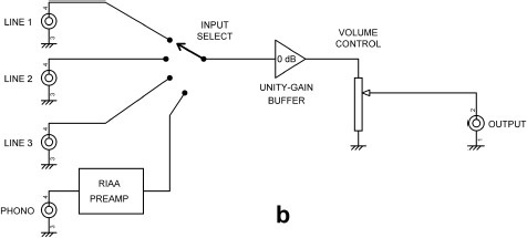
If a unity-gain buffer stage is added after the selector switch, as in Figure 4.1b, the volume pot resistance can be reduced to much less than 10 kΩ, while presenting a high impedance to the sources. If a 5532 is used for the buffer there is no technical reason why the pot could not be as low as 1 kΩ, which will give a much more useable maximum output impedance of only 250 Ω and also reduce Johnson noise by 10 dB. Note that an internal phono preamplifier has also been added. Now we’ve paid for a power supply, it might as well supply something else. Alternatively the phono amplifier can be external; since there is no gain in the preamplifier there will still be potential overload margin problems.
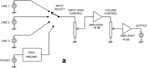
A unity-gain buffer still leaves us with a “preamplifier” that has a maximum gain of only one. Normally only CD players and other digital sources with an output of 2 Vrms can fully drive a power amplifier without additional gain, and there are some high-power amplifiers that require more than this for full output. iPods appear to have a maximum output of 1.2 Vrms. Output levels for tuners, phono amps, and so on vary but may be as low as 150 mV rms, while power amplifiers rarely have sensitivities lower than 500 mV. Clearly some gain would be good thing, so one option is adding a gain stage after the volume control as in Figure 4.1c. The output level can be increased and the output impedance kept down to 100 Ω or lower.
This amplifier stage introduces its own difficulties. If its nominal output level with the volume control fully up is taken as 1 Vrms for 150 mV in, which will let us drive most power amps to full output from most sources most of the time, we will need a gain of 6.7 times or 16.5 dB. If we decide to increase the nominal output level to 2 Vrms, to be sure of driving most if not all exotica to its limits, we need 22.5 dB. The problem is that the gain stage is amplifying its own noise at all volume settings and amplifying a proportion of the Johnson noise of the pot whenever the wiper is off the zero stop. The noise performance will therefore deteriorate markedly at low volume levels, which are the ones most used.
Adding amplification makes it easier to design the phono amplifier as it does not need to be able to drive a power amplifier directly and so requires less gain, and the overload margin is better.
Balanced Line Inputs
Balanced inputs are now common on preamplifiers with aspirations to quality. They ignore (to a first approximation) noise and hum currents in ground connections and allow hum loops to be rendered harmless. The only drawback seems to be the need for slightly more expensive cables and connectors, and of course you have to pay for the balanced input amplifier that converts the balanced signal back to single ended and at the same time cancels out ground noise and hum. But … there is another disadvantage which is rarely discussed in polite circles, and this has implications for the design of external phono amplifiers.
Balanced inputs are inherently noisier than unbalanced inputs by a large margin, in terms of the noise generated by the input circuitry itself rather than external noise. This may appear paradoxical, but it is all too true. Many people feel that this is the wrong way round. Surely the balanced input, with its professional XLR connector and its much-vaunted rejection of ground noise, should be completely superior? Well, it is—except as regards the internal noise generated by a balanced input amplifier.
If we assume that the unbalanced input stage is a 5532 voltage-follower, then with its input terminated by 50 Ω to ground the output noise is a very low −119.0 dBu over the usual 22–22 kHz bandwidth. This is because there are no series input resistors and no feedback resistors, so the noise seen is only the unamplified voltage noise of the opamp. If however the unbalanced input stage is configured to give gain, its noise output will inevitably be greater.
A balanced input stage is by comparison regrettably noisy. If it is built with 10 kΩ resistors and a 5532 section, as in the standard differential circuit of Figure 4.2a, the noise output is −104.8 dBu with both inputs similarly terminated. This is a 14 dB discrepancy which is both clearly audible and hard to explain away to suspicious potential customers.
The extra noise is due to the relatively high resistor values around the opamp which generate Johnson noise, and also the effect of opamp current noise flowing in these resistors. Their value cannot be reduced in Figure 4.2a without reducing the input impedances to below what is acceptable. If however two input buffers are added as in Figure 4.2b, the input impedances are defined solely by R5 and R6, and therefore resistors R1–R4 can be much reduced in value, here to 820 Ω. This reduces the output noise to −110.2 dB, which is 5.4 dB quieter than Figure 4.2a, but still noisier than the unbalanced voltage-follower.


This technique can be carried much further; the use of multiple input buffers and multiple amplifiers, whose noncorrelated noise partially cancels, allows us to get to within 2 dB of the unbalanced input without using anything more exotic than 5532s; see Table 4.1. However this requires quadruple input buffers and quadruple differential amplifiers, so the extra complexity is not negligible. Getting closer than that requires more expensive opamps such as the LM4562 or the AD797; both of these are a mixed blessing because they have lower voltage noise but higher current noise than the 5532. The technique, using double buffers and quad differential amplifiers, was used in the Cambridge Audio 840W power amplifier, a design of mine which, I might modestly mention in passing, won a CES Innovation Award in January 2008. There is much more on this method in Small Signal Audio Design.[2]
The important conclusion is that unless you are prepared to deploy a lot of hardware, the balanced input will be noisier than the unbalanced input. This has implication for the design of external phono amplifiers. If there are ground current problems, then using a balanced link will fix them, and it is not necessary for the sending equipment to have balanced output; connecting the cold (out-of-phase) balanced input to the output ground of the external source will give the full noise rejection that the balanced input is capable of; this is limited by its common-mode rejection ratio (CMRR). However, if the phono amplifier does have a balanced output, then the signal level in the connecting cable is effectively doubled, and the signal/noise ratio of the balanced input is improved by 6 dB. This means we can use much less hardware and still have a balanced input that is as quiet as the quietest of unbalanced inputs. Table 4.1 shows this can be achieved with single 5532 buffers and dual 5532 diff amps, requiring just two 5532 packages per channel.
I therefore recommend that external phono amplifiers should always have balanced outputs if they are expected to drive balanced inputs, solely to reduce the effect of noise in the balanced input. The extra cost is not great; see Chapter 14 for more on this.
Buffer type |
Differential amplifier |
Noise output |
Improvement over 4 × 10 kΩ diff amp dB |
Noisier than unbal input by dB |
|---|---|---|---|---|
5532 voltagollower |
−119.0 |
0.0 dB ref |
||
None |
Standard diff amp 10k 5532 |
−104.8 |
0.0 dB ref |
14.2 |
Single 5532 |
Single diff amp 820R 5532 |
−110.2 |
5.4 |
8.8 |
Single 5532 |
Dual diff amp 820R 5532 |
−112.5 |
7.4 |
6.5 |
Single 5532 |
Quad diff amp 820R 5532 |
−114.0 |
9.2 |
5.0 |
Dual 5532 |
Quad diff amp 820R 5532 |
−116.2 |
11.4 |
2.8 |
Quad 5532 |
Quad diff amp 820R 5532 |
−117.0 |
12.2 |
2.0 |
Quad 5532 |
Quad diff amp 820R LM4562 |
−118.9 |
14.1 |
0.1 |
A ground-cancelling output on an external phono amplifier, driving an unbalanced input on the preamplifier, would give the same rejection of ground noise but lower electronic noise in the link; it is also more economical on components. See Chapter 14 for all about ground- cancelling outputs.
Balanced Line Input Selection
If you have more than one balanced input, there are two ways to implement input selection. Figure 4.3a shows separate balanced input amplifiers for each balanced input; if you have a lot of balanced inputs this puts the cost up.
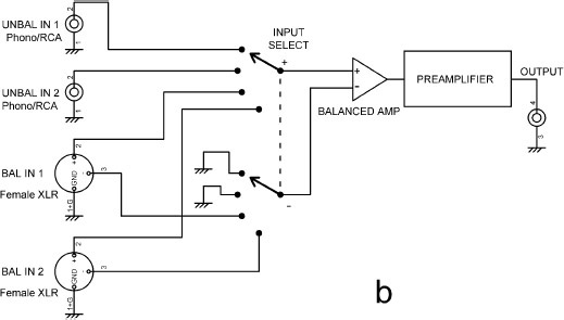
Alternatively you can have just one balanced input amplifier and use a 4-pole select switch as in Figure 4.3b, so that the XLR connectors are the only part added for each extra input. This saves electronics cost but increases the cost of the select switch, and this is likely to dominate. Another drawback is that the unbalanced inputs have to go through a relatively noisy balanced input amplifier. Note that the cold input of this amplifier is grounded when unbalanced inputs are in use. I used this technique in the Linear Audio low-noise preamplifier,[3] where the gain of the balanced input stage was variable over a limited range to implement an active balance control.
Amplification and the Gain-Distribution Problem
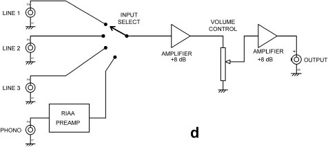
One answer to the noise/headroom issue in preamplifiers is to take the total gain and split it so there is some before and some after the volume control, so there is less gain amplifying the noise at low volume settings. One version of this is shown in Figure 4.1d. The question is—how much gain before, and how much after? This is inevitably a compromise, and it might be called the gain-distribution problem. Putting more of the total gain before the volume control reduces the headroom because there is no way to reduce the signal level, while putting more after increases the noise output at low volume settings. The first amplifier is sometimes called the normalisation amplifier, because after it the signals are at a standard nominal level. This may involve it having different gain for different inputs, which complicates the input selection switch.

If you are exclusively using sources with a predictable output, of which the 2 Vrms from a CD player will be the maximum, the overload situation is well defined, and if we assume that the pre-volume gain stage is capable of at least 8 Vrms out, so long as the pre-volume- control gain is less than four times there will never be a clipping problem. However, phono cartridges, particularly moving-coil ones, which have a very wide range of sensitivities, produce much less predictable outputs after fixed-gain preamplification, and it is a judgement call as to how much safety margin is desirable.
As an aside, it’s worth bearing in mind that even putting a unity-gain buffer before the volume control, which we did as the first step in preamp evolution, does place a constraint on the signal levels that can be handled, albeit at rather a high level of 8–10 Vrms depending on the supply rails in use. There is also the ultimate constraint that a volume-control pot can only handle so much power, and the manufacturers ratings are surprisingly low, sometimes only 50 mW. This means that a 10 kΩ pot would be limited to 22 Vrms across it, and if you are planning to use lower resistance pots than this to reduce noise, their power rating needs to be kept very much in mind.
Whenever a compromise appears in engineering, you can bet that someone will try to find a way round it and get the best of both worlds. What can be done about the gain-distribution dilemma?
One possibility is the use of a special low-noise amplifier after the volume control, combined with a low- resistance volume pot as suggested earlier. This could be done either by a discrete device and opamp hybrid stage or by using a multiple opamp array, as described in Chapter 1. It is doubtful if it is possible to obtain more than a 10 dB noise improvement by these means, but it would be an interesting project.
Another possible solution is the use of double gain controls. There is an input gain control before any amplification stage which is used to set the internal level appropriately, thus avoiding overload, and after the active stages there is an output volume control, which gives the much-desired silence at zero volume. See Figure 4.4a. The input gain controls can be separate for each channel, so they double as a balance facility; this approach was used on the Radford HD250 amplifier and also in one of my early preamplifier designs.[4] This helps to offset the cost of the extra pot. However, having two gain controls is operationally rather awkward, and however attenuation and fixed amplification are arranged, there are always going to be some trade-offs between noise and headroom. It could also be argued that this scheme does not make a lot of sense unless some means of metering the signal level after the input gain control is provided, so it can be set appropriately.
If the input and output gain controls are ganged together, to improve ease of operation at the expense of flexibility, this is sometimes called a distributed gain control.
Active Gain Controls
The noise/headroom compromise is completely avoided by replacing the combination of volume-control-and- amplifier with an active gain control, i.e. an amplifier stage whose gain is variable from near zero to the required maximum; see Figure 4.4b. We get lower noise at gain settings below maximum, and we can increase that maximum gain so even the least sensitive power amplifiers can be fully driven, without impairing the noise performance at lower settings. We also get the ability to generate a quasi-logarithmic law from a linear pot, which gives excellent channel balance as it depends only on mechanical alignment. The only snags are that:
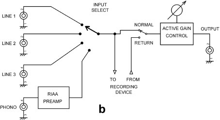
- a) most active gain controls phase-invert, though this can be corrected by suitable connection of a balanced input or balanced output stage or a Baxandall tone control.
- b) the noise out is very low but not zero at zero volume as it would be with a passive pot, since the noise gain does not fall below unity.
Balance Controls
I assert that any preamplifier, be it passive, active, or based on quantum entanglement, needs a balance control to be usable. We do not all have precisely symmetrical listening spaces. A channel gain imbalance of 10 dB is quite enough to shift the stereo image wholly to one side, and there is no need to fade out one channel totally. A passive balance control introduces the same noise/headroom compromise as a volume control, and an active-gain solution is preferred. Either a balanced input stage or a tone control can have its gain made variable over a limited range.
Tone Controls
Let us now consider adding tone controls. They have been unfashionable for a while, but this is definitely changing now. I think they are absolutely necessary, and it is a startling situation when, as frequently happens, anxious inquirers to hi-fi advice columns are advised to change their loudspeakers to correct excess or lack of bass or treble. This is an extremely expensive alternative to tone controls.
There are many possible types, but one thing most of them have in common is that they must be fed from a low-impedance source to give the correct boost/cut figures and predictable EQ curves. Likewise most of them, and certainly all the really useful types, including the famous Baxandall configuration, give a phase inversion. Since there is now pretty much a consensus that all audio equipment should maintain absolute phase polarity for all input and outputs, this can be highly inconvenient. Adding another inverting stage to do nothing but correct the phase is not an attractive prospect.
However, as noted earlier, this phase inversion can very neatly be undone by the use of an active gain control, which also uses shunt feedback and so also phase-inverts.
The tone control can be placed before or after the active gain control in Figure 4.4b, but if placed afterwards it generates noise that cannot be turned down. Putting it before the active gain control reduces headroom if boost is in use, but if we assume the maximum boost used is +10 dB, the tone control will not clip until an input of 3V rms is applied, and domestic equipment rarely generates such levels. It therefore seems best to put the tone control before the active gain control, and this is exactly what I did in most of my preamplifier designs. See [1], [3], [5], and [6].
Phono Amplifier Integration
Having looked briefly at some of the issues in preamplifier design, we can turn again to the question of how best to integrate a phono amplifier into the rest of the preamplifier. It is assumed that the preamp is based on opamp technology, and so the maximum signal that can be handled is about 10 Vrms.
First we will assume that the phono amplifier has a fixed gain. If the output of the phono amplifier is simply treated as just another line input, then the output level will need to be high to match line inputs from digital sources; otherwise there will be annoying level changes on switching sources. This means the nominal output from the phono amp will have to be 2 Vrms for a 5 mV rms (1 kHz) input; this limits the headroom (more often called the overload margin in phono amplifiers) to 10/2 = 5 times or 14 dB. This is a very small safety margin considering the unpredictability of vinyl velocities and the wide range of MC cartridge sensitivities; 30 dB or more overload margin is expected in quality equipment. Line inputs fed by digital equipment do not suffer this problem because their maximum output is rigidly defined.
So how do we deal with this? There are essentially three ways:
- 1) The preamplifier has a dedicated low-level line input. This may use a separate amplifier stage so the phono amp can have a lower nominal output and a correspondingly greater overload margin, though there is then of course the problem of clipping in the second amplifier. This is not very feasible unless both bits of equipment are made by the same company.
- 2) Another option is to switch the gain of the normalisation amplifier. This doubles the complexity of the source-select switch and will probably require precautions to avoid changes in DC offset, which will cause thumps and bumps.
- 3) A better solution is for the phono amplifier to have the variable gain. Making the gain continuously variable requires a dual-gang pot and will introduce stereo tracking errors, unless something like the Baxandall active volume stage is used, which allows linear pots to be used and cancels out the effects of track resistance changes. Continuously variable gain is not particularly useful, and switched gain, say with 5 dB steps, is much to be preferred.
The issues involved in designing variable-gain phono stages are dealt with in Chapter 5 and Chapter 6.
References
1. Self, D. “Preamplifier 2012” Elektor, Apr, May, June 2012.
2. Self, D. Small Signal Audio Design. 2nd edition. Focal Press, 2015. ISBN: 978-0-415-70974-3 (hbk) ISBN: 978-0-415-70973-6 (pbk) ISBN: 978-1-315-88537-7 (ebk).
3. Self, D. “A Low Noise Preamplifier With Variable-Frequency Tone Controls” Linear Audio, Volume 5, pub. Jan Didden, pp. 141–162.
4. Self, D. “An Advanced Preamplifier” Wireless World, Nov 1976.
5. Self, D. “A Precision Preamplifier” Wireless World, Oct 1983.
6. Self, D. “Precision Preamplifier 96” Electronics World, July/Aug and Sept 1996.