
Chapter 6
Signals From Vinyl
Levels and Limitations
Cartridge Types
This chapter deals with the signal levels generated by moving-magnet (MM) cartridge inputs and how this interacts with their special loading requirements and the need for RIAA equalisation. MM cartridges have been for many years less popular than moving-coil (MC) cartridges, but seem to be staging a comeback. However it would be relatively unusual nowadays to design a phono input that accepted MM inputs only. There are several ways to design a combined MM/MC input, but the approach that gives the best results is to design an MM preamp that incorporates the RIAA equalisation and put a flat-response low-noise head amplifier in front of it to get MC inputs up to MM levels. This allows the head amp to operate in the best conditions for low noise. A large part of this chapter is devoted to the tricky business of RIAA equalisation and so is equally relevant to MC input design. Almost all modern cartridges are of these two types, though Grado makes a moving-iron (MI) series; this is essentially a variation on MM.
Ceramic cartridges were still very much around when I first got into the audio business, but they now seem to be a rare example of an obsolete audio technology that no-one wants to revive. Ceramic cartridges have elements of Rochelle salt (in early versions, often called crystal pickups) or PZT (in ceramic versions) which generate electricity when flexed by the stylus. They look like a pure capacitance of around 200 pF to an amplifier input, and given a suitably high-impedance load, greater than 2 MΩ, they respond to stylus displacement rather than velocity. This led people to say that RIAA equalisation was not required, though this seems to overlook the presence of the 2-octave plateau in the middle of the RIAA characteristic. With 2 MΩ loading the output was in the range of 200–600 mV rms, much higher than the output of MM cartridges. This did not necessarily simplify preamplifier circuitry because of the need to establish a 2 MΩ input impedance; there is no real difficulty in doing this even with low-beta BJTs, as described in Chapter 3, but a few more parts are needed. Alternatively the cartridge can be more heavily loaded and equalisation applied. These two philosophies of ceramic cartridge termination were described in a 1969 article by Linsley-Hood,[1] and there was a thorough discussion of the whole business by Burrows in 1970.[2], [3]
The tracking force for ceramic cartridges is usually higher than that of MM or MC, often being on the order of 3 to 5 grams, and the increased groove wear is one powerful reason for not using them today. Sonotone and Acos were major ceramic cartridge manufacturers. The first cartridge I ever owned was a Sonotone 9TA; I still have it. Like most of its kind, it was a turnover cartridge; in other words there were two styli, one on each side of the cantilever. One was for microgroove LPs and the other for coarse-groove 78s, and they were selected by turning over the cantilever with a little plastic tab. This type of cartridge is still sometimes used for transcribing old 78 rpm records. An excellent account of the history of Sonotone cartridges can be found in and online history of the company.[4]
Strain-gauge cartridges also have a long history and are still with us today. Those made by Sound-Smith[5] appear to have a good reputation, though I have no experience with them myself. They are also sensitive to stylus displacement rather than stylus velocity (as MM and MC cartridges are). Naturally they require a specialised preamplifier, and the whole setup is not cheap.
Capacitance pickups, aka “FM pickups” or “electrostatic pickups,” consist of a small capacitor, one plate of which is wiggled by the stylus; the change in capacitance frequency modulates an oscillator, and the signal is decoded by standard FM-receiver technology. These were made by Weathers; the relevant patent appears to be US4,489,278, granted to Paul Weathers in 1984. Stax also made them; their first capacitance cartridge was the mono CP-20 introduced in 1952, the stereo CPS-40 not appearing until 1962. In 1977 Stax introduced a new technology, the CP-Y cartridge, having a permanent electret element and a head-amplifier IC built into the cartridge body. Shortly afterwards, their FM system was discontinued.
Moving-Magnet and Moving-Coil Cartridges
Moving-magnet (MM) cartridges create a signal voltage by creating a moving magnetic field which induces a voltage in fixed coils. The coils do not move and so can be relatively heavy, with a large number of turns to generate a relatively large voltage, around 5 mV rms. In contrast moving-coil cartridges move lightweight coils with few turns in a fixed magnetic field, so generally the output is much lower, with two clusters around 100–300 uV and 500–700 uV. Moving-coil cartridges are dealt with in more detail in Chapter 11.
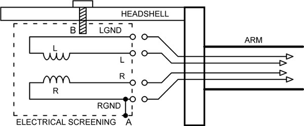
Both types are generally connected as shown in Figure 6.1. The major variation is whether or not the metal screening of the cartridge (to screen electric fields rather than magnetic ones, which is much less practicable, especially given the weight limitations) is connected to one of the signal grounds or not. If it is, as at A, then use of a metal headshell on a grounded arm will create a ground loop via the fixing screws B; nylon fixing screws solve this effectively. If the metal screening is not grounded and a nonmetal headshell is used, the screening is ungrounded, and electric fields from the turntable electrics will cause severe hum. Connection A was/is fitted to many Shure cartridges, as a metal tab which could be removed with care. At least one manufacturer has not fitted any electric screening to its cartridges, resulting in endemic hum problems.
The Vinyl Medium
The vinyl disc as a medium for music delivery in its present form dates back to 1948, when Columbia introduced microgroove 33⅓ rpm LP records. These were followed soon after by microgroove 45 rpm records from RCA Victor. Stereo vinyl did not appear until 1958. The introduction of Varigroove technology, which adjusts groove spacing to suit the amplitude of the groove vibrations, using an extra look-ahead tape head to see what the future holds, allowed increases in groove packing density. This density rarely exceeded 100 grooves per inch in the 78 rpm format, but with Varigroove 180–360 grooves/inch could be used at 33⅓ rpm.
While microgroove technology was unquestionably a considerable improvement on 78 rpm records, any technology that is 60 years old is likely to show definite limitations compared with contemporary standards, and indeed it does. Compared with modern digital formats, vinyl has a restricted dynamic range and poor linearity (especially at the end of a side) and is very vulnerable to permanent and irritating damage in the form of scratches. Even with the greatest care, scratches are likely to be inflicted when the record is removed from its sleeve. This action also generates significant static charges which attract dust and lint to the record surface. If not carefully removed, this dirt builds up on the stylus and not only degrades the reproduction of high- frequency information today but may also damage it in the future if it provokes mistracking.
Vinyl discs do not shatter under impact like the 78 shellac discs, but they are subject to warping by heat, improper storage, or poor manufacturing quality control. Possibly the worst feature of vinyl is that the stored material is degraded every time the disc is played, as the delicate high-frequency groove modulations are worn away by the stylus. When a good turntable with a properly balanced tone arm and correctly set up low-mass stylus is used this wear process is relatively slow, but it nevertheless proceeds inexorably. The stylus suffers wear too.
However, for reasons that have very little to do with logic or common-sense, vinyl is still very much alive. Even if it is accepted that as a music-delivery medium it is technically as obsolete as wax cylinders, there remain many sizable album collections that it is impractical to replace with CDs and would take an interminable time to transfer to the digital domain. I have one of them. Disc inputs must therefore remain part of the audio designer’s repertoire for the foreseeable future, and the design of the specialised electronics to get the best from the vinyl medium is still very relevant.
Vinyl Problems: Spurious Signals
It is not easy to find dependable statistics on the dynamic range of vinyl, but there seems to be general agreement that it is in the range 50 to 80 dB, the 50 dB coming from the standard-quality discs and the 80 dB representing direct-cut discs produced with quality as the prime aim. My own view is that 80 dB is rather optimistic.
The most audible spurious noise coming from vinyl is that in the midfrequencies, stemming from the inescapable fact that the music is read by a stylus sliding along a groove of finite smoothness. There is nothing that the designer of audio electronics can do about this; the levels involved are examined in Chapter 9 on noise.
Scratches create clicks that have a large high-frequency content, and it has been shown that they can easily exceed the level of the audio.[6] It is important that such clicks do not cause clipping or slew-limiting, as this makes their subjective impact worse. Lowpass filters can remove the ultrasonic disturbances and should be placed as early as possible in the signal path; see Chapter 13.
The signal from a record deck also includes copious amounts of low-frequency noise, which is often called rumble; it is typically below 30 Hz. This can come from several sources:
- 1) Mechanical noise generated by the motor and turntable bearings and picked up by the stylus/arm combination. These tend to be at the upper end of the low-frequency domain, extending up to 30 Hz or thereabouts. This is a matter for the mechanical designer of the turntable, as it clearly cannot be filtered out without removing the lower part of the audio spectrum.
- 2) Room vibrations will be picked up if the turntable and arm system is not well isolated from the floor. This is a particular problem in older houses where the wooden floors are not built to modern standards of rigidity and have a perceptible bounce to them. Mounting the turntable shelf to the wall usually gives a major improvement. Subsonic filtering is effective in removing room vibration.
- 3) Low-frequency noise from disc imperfections. This is the worst cause of disturbances. They can extend as low as 0.55 Hz, the frequency at which a 33⅓ rpm disc rotates on the turntable, due to large-scale disc warps. Warping can also produce ripples in the surface, generating spurious subsonic signals up to a few hertz at surprisingly high levels. These can be further amplified by a poorly controlled resonance of the cartridge compliance and the pickup arm mass. When woofer speaker cones can be seen wobbling—and bass reflex designs with no cone loading at very low frequencies are the worst for this—disc warps are usually the cause. Subsonic filtering is again effective in removing this.
(As an aside, I have heard it convincingly argued that bass reflex designs have only achieved their current popularity because of the advent of the CD player, with its greater bass signal extension but lack of subsonic output.)
Some fascinating data on the subsonic output from vinyl was given in an article by Tomlinson Holman [7] which shows that the highest warp signals occur in the 2 to 4 Hz region, being some 8 dB less at 10 Hz. By matching these signals with a wide variety of cartridge-arm combinations, he concluded that to accommodate the very worst cases, a preamplifier should be able to accept not less than 35 mV rms in the 3–4 Hz region. This is a rather demanding requirement, driven by some truly diabolical cartridge-arm setups that accentuated subsonic frequencies by up to 24 dB.
Since the subsonic content generated by room vibrations and disc imperfections tends to cause vertical movements of the stylus, the resulting electrical output will be out of phase in the left and right channels. The use of a central mono subwoofer system that sums the two channels will provide partial cancellation, reducing the amount of rumble that is reproduced. It is however still important to ensure that subsonic signals do not reach the left and right speakers.
For a great deal of information on subsonic filtering, see Chapter 12.
Vinyl Problems: Distortion
The reproduction of vinyl involves other difficulties apart from the spurious signals mentioned earlier: Distortion is a major problem. It is pretty obvious that the electromechanical processes involved are not going to be as linear as we now expect our electronic circuitry to be. Moving-magnet and moving-coil cartridges add their own distortion, which can reach 1–5% at high levels.
Distortion gets worse as the stylus moves from the outside to the inside of the disc. This is called “end of side distortion” because it can be painfully obvious in the final track. It occurs because the modulation of the inner grooves is inevitably more compressed than those of the outer tracks, due to the constant rotational speed of a turntable. I can well recall buying albums and discovering to my chagrin that a favourite track was the last on a side.
It is a notable limitation of the vinyl process that the geometry of the recording machine and that of the replay turntable do not match. The original recordings are cut on a lathe where the cutting head moves in a radial straight line across the disc. In contrast, almost all turntables have a pivoting tone arm about 9 inches in length. The pickup head is angled to reduce the mismatch between the recording and replay situations, but this introduces side forces on the stylus and various other problems, increasing the distortion of the playback signal. A recent article in Stereophile[8] shows just how complicated the business of tone arm geometry is. SME produced a 12-inch arm to reduce the angular errors; I have one and it is a thing of great beauty, but I must admit I have never put it to use.
The vinyl process depends on a stylus faithfully tracking a groove. If the groove modulation is excessive, with respect to the capabilities of the cartridge/arm combination, the stylus loses contact with the groove walls and rattles about a bit. This obviously introduces gross distortion and is also very likely to damage the groove.
Vinyl Problems: Wow
A really disabling problem is “wow”; the slow cyclic pitch change resulting from an off-centre hole. Particularly bad examples of this used to be called “swingers” because they were so eccentric that they could be visibly seen to be rotating off-centre. I understand that nowadays the term means something entirely different and relates to an activity which sounds as though it could only be a distraction from critical listening.
Most of the problems that vinyl is heir to are supremely unfixable, but this is an exception; do not underestimate the ingenuity of engineers. In 1983 Nakimichi introduced the extraordinary TX-1000 turntable that measured the disc eccentricity and corrected for it.[9] A secondary arm measured the eccentricity of the run-out groove and used this information to mechanically offset the spindle from the platter-bearing axis. This process took 20 seconds, which I imagine could get a bit tedious once the novelty has worn off. This idea deserved to prosper, but CDs were coming; the timing was bad.
Vinyl Problems: Flutter
Flutter is rapid changes in pitch, rather than the slow ones that constitute wow. You would think that a heavy platter (and some of them are quite ridiculously massive) would be unable to change speed rapidly, and you would be absolutely right. But . .. the other item in the situation is the cartridge/arm combination, which moves up and down but does not follow surface irregularities because of the resonance between cartridge compliance and arm+cartridge mass. The stylus therefore moves back and forward in the groove, frequency-modulating the signal.
This and the other mechanical issues of turntables and arms are described in an excellent article by Hannes Allmaier,[10] who makes the important point that the ear is most sensitive to flutter at around 4 Hz, uncomfortably close to the cart/arm resonance region of 8–12 Hz.
Vinyl Problems: Tracking Force
The tracking force of a stylus in a groove is a highly important parameter. Too much force causes excessive groove wear, whereas too little permits mistracking, which sounds terrible and causes even more excessive groove wear. However, the tracking force varies significantly even with apparently flat vinyl, due to ... yes, the cart/arm resonance again.
Attempts to reduce the multiple bad effects of the cart/arm resonance include damping the arm with a silicone-filled dashpot, but this is messy business and has never caught on. The Shure M97xE carries a little carbon-fibre brush which can be swung to contact the vinyl surface and reduce the vertical forces on the stylus and hence its movement.
Vinyl Problems: Surface Damage
A vinyl disc is horribly vulnerable to damage, and the resulting clicks and ticks are thoroughly annoying. Scratches usually occur when sliding the disc in or out of the inner sleeve. While you cannot, as far as I know, mend groove damage, various electronic devices have been introduced with the aim of suppressing clicks. This obviously depends on being able to detect clicks and reliably distinguish them from musical transients. Clicks normally have a much higher slew rate than music, and this is the basis of their detection; they also tend to be out-of-phase, and this information is sometimes also used. When detected the click is suppressed by very briefly reducing the gain, ideally so that the resulting waveform “smears over” the site of the click on the waveform. In some versions the audio is delayed (a 5 us delay implemented by four cascaded allpass filters has been used), so the suppression circuitry has time to operate.
The best known of the declicking devices is the SAE 5000A Impulse Noise Reduction system introduced in 1980; many of these are still in use. The general view seems to be that given careful adjustment of the sensitivity control it works reasonably well but by no means perfectly. Declicking can also be done using DSP software; an excellent overview of this is given in a PDF by Godsill et al.[11]
Maximum Signal Levels on Vinyl
There are limits to the signal level possible on a vinyl disc, and they impose maxima on the signal that a cartridge and its associated electronics will be expected to reproduce. The exact values of these limits may not be precisely defined, but the way they work sets the ways in which maximum levels vary with frequency, and this is of great importance.
There are no variable-gain controls on RIAA inputs because implementing an uneven but very precisely controlled frequency response and a suitably good noise performance are quite hard enough without adding variable gain as a feature. No doubt it could be done, but it would not be easy, and the general consensus is that it is not necessary. The overload margin, or headroom, is therefore of considerable importance, and it is very much a case of the more the merrier when it comes to the numbers game of specmanship. The issue can get a bit involved, as a situation with frequency-dependent vinyl limitations, and frequency-dependent gain is often further complicated by a heavy frequency-dependent load in the shape of the feedback network, which can put its own limit on amplifier output at high frequencies. Let us first look at the limits on the signal levels which stylus-in-vinyl technology can deliver. In the diagrams that follow the response curves have been simplified to the straight-line asymptotes.
Figure 6.2a shows the physical groove amplitudes that can be put onto a disc. From subsonic up to about 1 kHz, groove amplitude is the constraint. If the sideways excursion is too great, the groove spacing will need to be increased to prevent one groove breaking into another, and playing time will be reduced. Well before actual breakthrough occurs, the cutter can distort the groove it has cut on the previous revolution, leading to “pre-echo” in quiet sections, where a faint version of the music you are about to hear is produced. Time travel may be fine in science fiction, but it does not enhance the musical experience. The ultimate limit to groove amplitude is set by mechanical stops in the cutter head.
There is an extra limitation on groove amplitude; out-of-phase signals cause vertical motion of the cutter, and if this becomes excessive it can cause it to cut either too deeply into the disc medium and dig into the aluminium substrate or lose contact with the disc altogether. An excessive vertical component can also upset the playback process, especially when low tracking forces are used; in the worst case the stylus can be thrown out of the groove completely. To control this problem the stereo signal is passed through a matrix that isolates the L-R vertical signal, which is then amplitude limited. This potentially reduces the perceived stereo separation at low frequencies, but there appears to be a general consensus that the effect is not audible. The most important factor in controlling out-of-phase signals is the panning of bass instruments (which create the largest cutter amplitudes) to the centre of the stereo stage. This approach is still advantageous with digital media, as it means that there are two channels of amplification to reproduce the bass information rather than one.
From about 1 kHz up to the ultrasonic regions, the limit is groove velocity rather than amplitude. If the disc cutter head tries to move sideways too quickly compared with its relative forward motion, the back facets of the cutter destroy the groove that has just been cut by its forward edges.
On disc replay, there is a third restriction—that of stylus acceleration, or to put it another way, groove curvature. This sets a limit on how well a stylus of a given size and shape can track the groove. Allowing for this at cutting time places an extra limitation on signal level, shown by the dotted line in Figure 6.2a. The severity of this restriction depends on the stylus shape; an old-fashioned spherical type with a tip diameter of 0.7 mil requires a roll-off of maximum levels from 2 kHz, while a (relatively) modern elliptical type with 0.2 mil effective diameter postpones the problem to about 8 kHz. The limit however still remains.
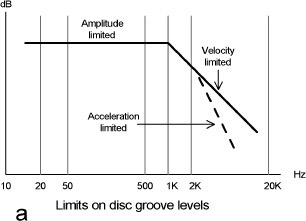
Thus disc-cutting and playback technology put at least three limits on the maximum signal level. This is not as bad a problem as it might be, because the distribution of amplitude with frequency for music is not flat with frequency; there is always more energy at LF than HF. This is especially true of the regrettable phenomenon known as rap music. For some reason there seems to be very little literature on the distribution of musical energy versus frequency, but a very rough rule is that levels can be expected to be fairly constant up to 1 kHz and then fall by something like 10 dB/octave. The end result is that despite the limits on disc levels at HF, it is still possible to apply a considerable amount of HF boost which, when undone at replay, reduces surface noise problems. At the same time the LF levels are cut to keep groove amplitude under control. Both functions are implemented by applying the inverse of the familiar RIAA replay equalisation at cutting time. More on the limitations affecting vinyl levels can be found on Jim Lesurf’s website.[12]
A reaction to the limitations of the usual 7-inch single was the 12-inch single, which appeared in the mid-1970s, before CDs arrived. The much greater playing area allowed greater groove spacing and higher recording levels. I bought several of these, in the 45 rpm format, and I can testify that the greater groove speed gave a much clearer and less distorted high end, definitely superior to 33 rpm LPs.
Having looked at the limitations on the signal levels put onto disc, we need to see what we will get back when we replay it. This obviously depends on the cartridge sensitivity. That issue is dealt with in the next section, but it might as well be said now that in general MM cartridge sensitivity varies over a limited range of about 7 dB, while MC sensitivity variation is much greater.
Since MM input stages do not normally have gain controls, it is important that they can accept the whole range of input levels that occur. A well-known paper by Tomlinson Holman[13] quotes a the worst-case peak voltage from an MM cartridge of 135 mV at 1 kHz given by Huntley in Reference [14]. This is equivalent to 95 Vrms at 1 kHz. He says: “[T]his is a genuinely worst-case combination which is not expected to be approached typically in practice.”
Shure are a well-known manufacturer of MM cartridges, and their flagship V15 phonograph cartridge series (the 15 in each model name referred to the cartridges’ 15-degree tracking angle), for many years set the standard for low tracking force and high tracking ability. Its development necessitated much research into the maximum levels on vinyl. Many other workers also contributed in this field. The results are usually expressed in velocity (cm/s) as this eliminates the effect of cartridge sensitivity. I have boiled down the Shure velocity data into Table 6.1. I have included the acceleration of the stylus tip required for the various frequency/velocity pairs; this is not of direct use, but given that the maximum sustained acceleration the human body can withstand is around 3 g, it surely makes you think. Since the highest MM cartridge sensitivity for normal use is 1.6 mV per cm/s, (see next section) Table 6.1 tells us that we need to be able to handle an MM input of 1.6 × 38 = 61 mV rms. This is not far out of line with the 95 mV rms quoted by Holman, being only 3.8 dB lower.
The website of Jim Lesurf[15] has many contemporary measurements of maximum groove velocities. The maximum quoted is 39.7 cm/s, which gives 1.6 × 39.7 = 63.5 mV rms. Rooting through the literature, the Pressure Cooker discs by Sheffield Labs were recorded direct to disc and are said to contain velocities up to 40 cm/s, giving us 1.6 × 40 = 64 mV rms. It is reassuring that these maxima do not differ very much. On the other hand, the jazz record Hey! Heard The Herd by Woody Herman (Verve V/V6 8558, 1953) is said to have a peak velocity of 104 cm/s at 7.25 kHz,[16] but this seems out of line with all other data. If it is true, the input level from the most sensitive cartridge would be 1.6 × 105 = 166 mV rms.
So we may conclude that the greatest input level we are likely to encounter is 64 mV rms, though that 166 mV rms should perhaps not be entirely forgotten.
The maximum input a stage can accept before output clipping is set by its gain and supply rails. If we are using normal opamps powered from ±17V rails, we can assume an output capability of 10 Vrms. Scaling this down by the gain in each case gives us Table 6.2, which also shows the output level from a nominal 5 Vrms input.
Clearly if we want to accept a 64 mV rms input the gain cannot much exceed +40 dB. In fact a gain of +43.8 dB will just give clipping for 64 mV rms in. If we want to accept the Woody Herman 166 mV rms, then the maximum permissible gain is +35.6 dB. I would suggest that a safety margin of at least 5 dB should be added, so we conclude that 30 dB (1 kHz) is an appropriate gain for an MM input stage; this will accept 316 mV rms from a cartridge before clipping. A recent review of a valve phono stage[17] described an MM input capability of 300 mV rms as “extremely generous”, and I reckon that an input capability around this figure will render you immune to overload forever, and be more than adequate for the highest quality equipment. The stage output with a nominal 5 mV rms input is only 158 mV rms, which is not enough to operate your average power amplifier, and so there will have to be another amplifying stage after it. This must have variable gain or be preceded by a passive volume control, for otherwise it will clip before the first stage and reduce the overload margin.

While we must have a relatively low gain in the MM stage to give a good maximum signal capability, we do not want it to be too low, or the signal/noise ratio is likely to be degraded as the signal passes through later stages. It is one of the prime rules of audio that you should minimise the possibility of this by getting the signal up to a decent level as soon as possible, but it is common practice and very sensible for the MM output to go through a unity-gain subsonic filter before it receives any further amplification; this is because the subsonic stuff coming from the disc can be at disturbingly high levels.
Gain dB |
Gain times |
Max input mV rms |
Overload margin dB |
5 V rms would be raised to: |
|---|---|---|---|---|
50 |
316 |
32 mV |
16 dB |
1580 Vrms |
45 |
178 |
56 mV |
21 dB |
890 Vrms |
40 |
100 |
100 mV |
26 dB |
500 Vrms |
35 |
56.2 |
178 mV |
31 dB |
281 Vrms |
30 |
31.6 |
316 mV |
36 dB |
158 Vrms |
25 |
17.8 |
562 mV |
41 dB |
89 Vrms |
20 |
10 |
1000 mV |
46 dB |
50 Vrms |
In the history of preamplifiers MM input overload margin used to be a test of macho—this is less true now, as the changeover to MC cartridges with a wide range of output levels makes a single input overload figure much less meaningful.
Moving-Magnet Cartridge Sensitivities
Having looked at the limitations on the signal levels put onto disc, we need to see what levels we will get back when we replay it. The level reaching the preamplifier is clearly proportional to the cartridge sensitivity. Due to their electromagnetic nature MM cartridges respond to stylus velocity rather than displacement (the same applies to MC cartridges), so output voltage is usually specified at a velocity of 5 cm/sec. That convention is followed throughout this chapter.
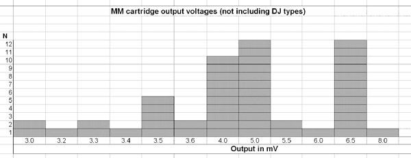
A survey of 72 MM cartridges on the market in 2012 showed that they fall into two groups—what might be called normal hi-fi cartridges (57 of them) and specialised cartridges for DJ use (15 of them). The DJ types have a significantly higher output than the normal cartridges—the Ortofon Q-Bert Concorde produces no less than 11 mV, the highest output I could find. It seems unlikely that the manufacturers are trying to optimise the signal-to-noise ratio in a DJ environment, so I imagine there is some sort of macho “my cartridge has more output than yours” thing going on. Presumably DJ cartridges are also designed to be exceptionally mechanically robust. We will focus here on the normal cartridges, but to accommodate DJ types all you really need to do is allow for 6 dB more input level to the preamplifier.
The outputs of the 58 normal cartridges at a velocity of 5 cm/sec are summarised in the histogram of Figure 6.3. The range is from 3.0 mV to 8.0 mV, with significant clumps around 4–5 mV and 6.5 mV. If we ignore the single 8.0 mV cartridge, the output range is restricted to 3.0 to 6.5 mV, which is only 6.7 dB. This is a very small range compared with the very wide one shown by MC cartridges and makes the design of a purely MM input a simpler matter. There is no need to provide different amplifier sensitivities, as a 6.7 dB range can be easily accommodated by adjustment of a volume control later in the audio path.
Overload Margins and Amplifier Limitations
The safety factor between a nominal 5 mV rms input and the clipping point may be described as either the input headroom in mV rms or the “overload margin”, which is the dB ratio between the nominal 5 mV rms input and the maximum input. Table 6.2 shows that an MM stage with a +35 dB gain (1 kHz) gives an output of 280 mV, an input overload level of 178 mV rms and an overload margin of 31 dB, which might be called very good. A +30 dB (1 kHz) stage gives a nominal 158 mV out, an input overload level of 316 mV rms, and an overload margin of 36 dB, which is definitely excellent, giving 5 dB more headroom.
The maximum input capability of an MM stage is not always defined by simple frequency-independent clipping at its output. Things may be complicated by the stage output capability varying with frequency. An RIAA feedback network, particularly one designed with a relatively low impedance to reduce noise, presents a heavier load as frequency rises because the impedance of the capacitors falls. This heavy loading at HF was very often a major cause of distortion and headroom-limitation in discrete RIAA stages that had either common-collector or emitter-follower output topologies with highly asymmetrical drive capabilities; for example an NPN emitter-follower is much better at sourcing current than sinking it. With conventional discrete designs the 20 kHz output capability, and thus the overload margin, was often reduced by 6 dB or even more. Replacing the emitter resistor of an emitter-follower with a current source much reduces the problem, and the very slight extra complication of using a push-pull Class-A output structure can bring it down to negligible proportions; for more details see Chapter 10 on discrete MM input design. Earlier opamps such as the TL072 also struggled to drive RIAA networks at HF, as well as giving a very poor noise performance. It was not until the advent of the 5532 opamp, with its excellent load-driving capabilities, that the problem of driving low-impedance RIAA networks was solved; the noise performance was much better, too. However, if a low-impedance HF correction pole (more on this later) is being driven as well, there may still be some slight loss of output capability at 20 kHz.
We saw in the earlier section on spurious signals that Tomlinson Holman concluded that to accommodate the worst of the worst, a preamplifier should be able to accept not less than 35 mV rms in the 3–4 Hz region.[7] If the IEC Amendment is after the preamplifier stage and C0 is made very large so it has no effect (see Chapter 7), the gain in the 2–5 Hz region will have flattened out at +19.9 dB, so the equivalent overload level at 1 kHz will be need to be 346 mV rms, which is rather high. The +30 dB (1 kHz) gain stages examined in Chapter 7 have a 1 kHz overload level of 316 mV rms, which is only 0.8 dB below this rather extreme criterion; we are good to go. Using a +35 dB (1 kHz) gain stage instead would significantly reduce the safety margins.
Further headroom restrictions may occur when not all of the RIAA equalisation is implemented in one feedback loop. Putting the IEC Amendment roll-off after the preamplifier stage (as in Figure 7.3) means that very low frequencies are amplified by 3 dB more at 20 Hz than they otherwise would be, and this is then undone by the later roll-off. This sort of audio impropriety always carries a penalty in headroom as the signal will clip before it is attenuated, and the overload margin at 20 Hz is reduced by 3.0 dB. This effect reduces quickly as frequency increases, being 1.6 dB at 30 Hz and only 1.0 dB at 40 Hz. Whether this loss of overload margin is more important than providing an accurate IEC Amendment response is a judgement call, but in my experience it creates no trace of any problem in an MM stage with a gain of +30 dB (1 kHz). Passive-equalisation input architectures that put flat amplification before an RIAA stage suffer much more severely from this kind of headroom restriction, and it is quite common to encounter preamplifiers that claim to be high end, with a high-end price-tag but a very low-end overload margin of 20 to 22 dB. Bad show, chaps.
At the other end of the audio spectrum, adding an HF correction pole after the preamplifier to correct the RIAA response with low gains (see Figure 7.3 again) also introduces a compromise in the overload margin, though generally a much smaller one. A 30 dB (1 kHz) stage has a mid-band overload margin of 36 dB, falling to +33 dB at 20 kHz. Only 0.4 dB of this loss is due to the amplify-then-attenuate action of the HF correction pole, the rest being due to the heavy capacitative loading on A1 of both the main RIAA feedback path and the pole-correcting RC network. This slight compromise could be eliminated by using an opamp structure with greater load-driving capabilities, so long as it retains the low noise of a 5534A.
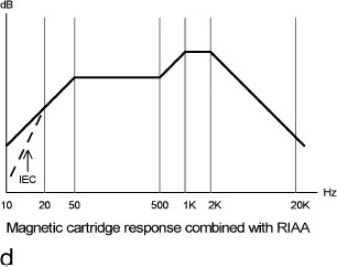
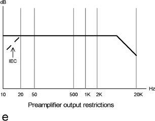
An attempt has been made to show these extra preamp limitations on output level in Figure 6.2e, and comparing Figure 6.2d, it appears that in practice they are almost irrelevant because of the falloff in possible input levels at each end of the audio band.
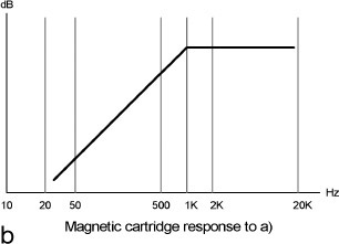
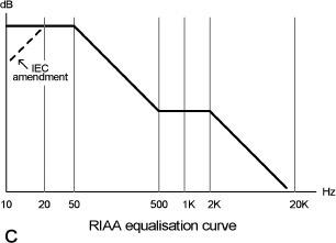
When the RIAA equalisation of Figure 6.2c is applied to the cartridge output of Figure 6.2b, the result looks like Figure 6.2d, with the maximum amplitudes occurring around 1–2 kHz. This is in agreement with Tomlinson Holman’s data.[7]
Figure 6.2e shows some possible output level restrictions that may affect Figure 6.2d. If the IEC Amendment is implemented after the first stage, there is a possibility of overload at low frequencies which does not exist if the amendment is implemented in the feedback loop by restricting C0. At the high end, the output may be limited by problems driving the RIAA feedback network, which falls in impedance as frequency rises.
To put all this into some sort of perspective, here are the 1 kHz overload margins for a few of my published designs. My first preamplifier, the “Advanced Preamplifier”,[18] achieved +39 dB in 1976, partly by using all-discrete design and ± 24V supply rails. A later discrete design in 1979[19] gave a tour-de-force +47 dB, accepting over 1.1 Vrms at 1 kHz, but I must confess this was showing off a bit and involved some quite complicated discrete circuitry, including the push-pull Class-A output stages mentioned in Chapter 10. Later designs such as the Precision Preamplifier[20] and its linear descendant the Precision Preamplifier ’96[21] accepted the limitations of opamp output voltage in exchange for much greater convenience in most other directions and still have an excellent overload margin of 36 dB.
References
1. Linsley-Hood, J. “Modular Pre-Amplifier Design” Wireless World, July 1969, p. 306.
2. Burrows, B. “Ceramic Pickup Equalisation: 1” Wireless World, July 1971, p. 321.
3. Burrows, B. “Ceramic Pickup Equalisation: 2” Wireless World, Aug 1971, p. 379.
4. Sonotone history. www.roger-russell.com/sonopg/sonopg.htm Accessed Nov 2016.
5. Sound-Smith. www.sound-smith.com/cartridges/sg.html Accessed Nov 2016.
6. Jones, M. “Designing Valve Preamps: Part 1” Electronics World, Mar 1996, p. 192.
7. Holman, T. “Dynamic Range Requirements of Phonographic Preamplifiers” Audio, July 1977, p. 74.
8. Howard, K. www.stereophile.com/reference/arc_angles_optimizing_tonearm_geometry/index.html Accessed June 2013.
9. Smith, A, and Miller, P. “Nakimichi TX-1000 turntable” Hi-Fi News, Aug 2016, pp. 118–123 (self- centering turntable).
10. Allmaier, H. “The Ins & Outs of Turntable Dynamics—and How They Mess Up Your Vinyl Playback” Linear Audio, Volume 10, Sept 2015, p. 14.
11. Godsill et al. www2.ece.ohio-state.edu/~schniter/ee597/handouts/restoration_chapter.pdf Accessed Dec 2016.
12. Lesurf, J. www.audiomisc.co.uk/HFN/LP1/KeepInContact.html Accessed June 2013.
13. Holman, T. “New Factors in Phonograph Preamplifier Design”.
14. Huntley, C. “Preamp Overload” Audio Scene Canada, Nov 1975, pp. 54–56.
15. Lesurf, J. www.audiomisc.co.uk/HFN/LP2/OnTheRecord.html Accessed June 2013.
16. Boston Audio Society. www.bostonaudiosociety.org/pdf/bass/BASS-05-03-7612.pdf Accessed June 2013.
17. Miller, P. Hi-Fi News, Review of Canor TP306 VR+ phono stage, Aug 2013, p. 25.
18. Self, D. “An Advanced Preamplifier Design” Wireless World, Nov 1976.
19. Self, D. “High Performance Preamplifier” Wireless World, Feb 1979.
20. Self, D. “A Precision Preamplifier” Wireless World, Oct 1983.
21. Self, D. “Precision Preamplifier 96” Electronics World, July/Aug and Sept 1996.