
Chapter 17
Moving-Magnet Inputs
Practical Designs
The closely observed designs given here will be handy for immediate use, and they also demonstrate many of the various techniques discussed in this book, with extra practical details added. There is much information on how to interface the stages properly and avoid bad loading effects. Input and output networks, and all practical details, are given so that each circuit is complete in itself.
Project 1: A Simple Single-Stage +40 dB Phono Amplifier
While this book contains much about achieving the highest quality, sometimes economy is the watchword. This design is intended to give that economy. It is a basic one-stage phono amplifier with a gain of +40 dB (1 kHz) intended for driving preamplifiers directly; the nominal output is 500 mV rms for 5 mV rms in; the maximum input is 100 mV rms, giving a +26 dB overload margin, which is not stupendous but adequate for all but the hottest cartridges and vinyl.
In the interests of economy, this circuit, unlike most in this book, has all resistors restricted to single E24 components, i.e. 1xE24 format. Single capacitors are also used, and Configuration-C employed to minimise total RIAA capacitance. The relatively high gain of +40 dB means that the HF correction pole can be omitted with only small errors introduced at the extreme HF; hence the absence of R3. This also leads to a low value for R0, so its noise contribution will be very small indeed; see Chapter 9 on noise. The only subsonic filtering is provided by a restricted value for C0. Its original value was 470 uF which gave −1.2 dB at 8 Hz, −13 dB at 1 Hz. When the resistor values were converted to the nearest E24, this introduced a response rise in the LF which could be partly countered by further reducing the value of C0 to 330 uF. This means of course that the response is to a small extent at the mercy of the C0 tolerances, and this is one of the many compromises inevitable in an economy design. You will recall that I cautioned against using electrolytics to set time-constants not only because of tolerance issues but because they distort if significant signal voltage appears across them; since the nominal signal level is 5 mV rms, this is not a problem here.
The exact component values that were the basis of this design can be found in Table 7.31; they were calculated for +40 dB (1 kHz) by adjusting the value of R0 so that so that C1 comes out as exactly 33 nF.
DC drain resistor R4 is very much noncritical, so it has been made 68 kΩ to match Rin and R1; this sort of thing makes component procurement easier. R5 is the output isolating resistor, which ensures stability into cable capacitance and is also non-critical so long as it is greater than 47 Ω, so it is set to 68 Ω to match R0. R4 comes before R5 to avoid a tiny but irritating loss in level of 0.009 dB.
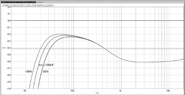
Figure 17.2 shows the RIAA response. The error is within ±0.2 dB (just), which I think is pretty good for so simple a circuit. The central trace is for C0 = 330 uF exactly, and those either side show the effect of a ±20% tolerance. C0 makes the response −2.6 dB at 8 Hz and −17 dB at 1 Hz; not exactly proper subsonic filtering but better than nothing. If desired the LF roll-off can be eliminated by making C0 1000 uF 6V3. The largest RIAA errors are introduced by converting C2 from 11.408 nF to the E12 value of 12 nF and R2 from 9.5723 kΩ to the E24 value 9.1 kΩ. The dotted line at −0.41 dB shows that the overall gain has been slightly reduced to +39.4 dB (1 kHz) compared with the original design value of +40 dB.
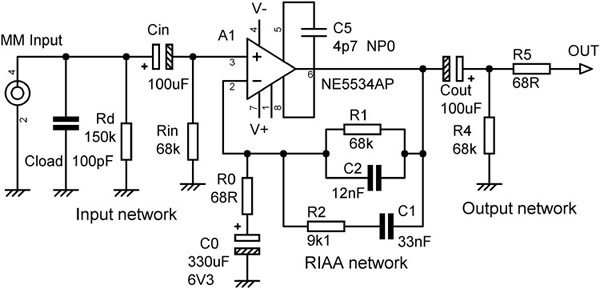
Figure 17.1 Project 1: Economy MM input with +40 dB (1 kHz) of gain, with 1xE24 resistors
Project 2: A Simple Single-Stage +40 dB Phono Amplifier Upgraded
In Project 1 we saw that the worst effects on the RIAA accuracy were due to forcing C2 to an E12 value and R2 to an E24 value. If we allow just a little more complexity, but without making every RIAA component multiple, we can make a remarkable improvement. The exact value of C2 is 11.408 nF, and we can get very close to that with 3x3n3 and 1x4n7 in parallel, giving 11.3 nF. These are small polystyrene capacitors and can be obtained inexpensively at 1% tolerance. The exact value of R2 is 9.5723 kΩ; 16 kΩ and 24 kΩ in parallel are only +0.29% high, with an effective tolerance of 0.72%.
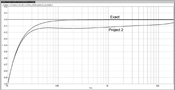
The RIAA accuracy is much improved, as shown in Figure 17.4. The gain at 1 kHz is now only 0.12 dB below the +40 dB aimed for, and relative to average gain the errors are within ±0.05 dB. However, bear in mind the effect of C0 tolerance. The response with exact component values is shown for comparison.
Most of the circuits in this book use multiple components for anything that is critical. Here however is an example of good results obtained with a halfway house between the 1xE24 and 2xE24 approaches.

Figure 17.3 Project 2: Economy MM input with +40 dB (1 kHz) of gain, with multiple components for R2 and C2
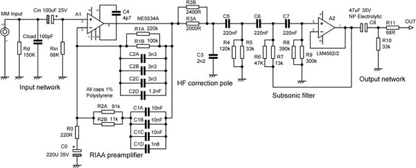
Project 3: An MM Amplifier With Subsonic Filter
The next design in Figure 17.5 has a lower gain of +30 dB (1kHz), giving a really first-class overload margin of 36 dB. It is based on the MM section of the Signal Transfer MM/MC phono amplifier.[1] I have used this circuit for many years, and it has given complete satisfaction to many customers, though in the light of the latest knowledge its Configuration-A could be changed to Configuration-C to economise on precision capacitors; this is done in Project 4. It includes a typical subsonic filter which is designed with a slow initial roll-off that implements the IEC amendment, so a separate network is not required. A 5534A is used at the input stage to get the best possible noise performance. A 5534A without external compensation has a minimum stable closed-loop gain of about 3 times; that is close to the gain at 20 kHz here, so a touch of extra compensation is required for stability. The capacitor used here is 4.7 pF, which experience shows is both definitely required and also gives completely reliable stability. This is tested by sweeping a large signal from 20 kHz downwards; single-frequency testing can miss this sort of problem.
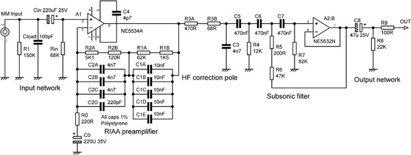
The resistors have been made more accurate by combining two E24 values. In this case they are used in series, and no attempt was made to try and get the values equal for the maximum reduction of tolerance errors. That statistical work was done at a later date. The Configuration-A RIAA network capacitances are made up of multiple 1% polystyrene capacitors for improved accuracy. Thus for the five 10 nF capacitors that make up C1, the standard deviation (square root of variance) increases by the square root of 5, while total capacitance has increased 5 times, and we have inexpensively built an otherwise costly 0.44% close-tolerance 50 nF capacitor. You will note that 5 × 10 nF capacitors are required, whereas a Configuration-C RIAA network can do the same job with 4 × 10 nF. The RIAA accuracy is within ± 0.1 dB 20 Hz–20 kHz.
C2 is essentially composed of three 4n7 components, and its tolerance is improved by √3, to 0.58%. Its final value is tweaked by the addition of C15. An HF correction pole R8, R9, C13 is fitted; the resultant loss of HF headroom is only 0.5 dB at 20 kHz, which I think I can live with.
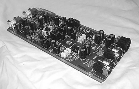
Immediately after the RIAA stage is the subsonic filter, a 3rd-order Butterworth highpass filter which also implements the IEC Amendment by using a value for R11 + R12 which is lower than that for maximal Butterworth flatness. In this respect the circuit shows its age a little, as since it was designed the use of IEC appears to have been pretty much abandoned. The stage also buffers the HF correction pole R8, R9, C13 from later circuitry and gives the capability to drive a 600 Ω load, if you can find one. A version of this design, using appropriate precision components and incorporating the MC amplifier in Chapter 11, is manufactured by the Signal Transfer Company in bare PCB, kit, and fully built and tested formats.[1] The balanced-output version is shown in Figure 17.6; the MC stage with its gain switch is at upper left, the MM section with its bank of precision polystyrene capacitors is in the middle, while lower right is the subsonic filter and balanced output stages with two XLR connectors.
Project 4: An MM Amplifier With Subsonic Filter: Upgraded
The next project is an update of Project 3, with the following changes:
- 1) The RIAA network has been converted to Configuration-C, and so the total capacitance required has been reduced from 64 nF to 43 nF without increasing the impedance of the RIAA network, by using the capacitance more efficiently. The gain is unchanged at +30 dB (1 kHz).
- 2) Critical resistors have been converted to optimal 2xE24 parallel pairs.
- 3) C3 reduced and R3 increased to reduce the loading of the HF correction pole on opamp A1 output. This has a consequence in that the loading effect of the subsonic filter on R3 is now greater, causing a 0.4 dB loss of gain above 40 Hz. This gentle slope in the response is completely obliterated by the start of the subsonic filter roll-off and is of no account, but the loss of 0.4 dB of headroom is not ideal. It can be avoided by placing a unity-gain buffer stage between C3 and C5; the LM4562 is recommended. This is a good example of the need to be careful when connecting stages together.
- 4) IEC amendment removed; the subsonic filter now has a standard 3rd-order Butterworth response −3 dB at 20 Hz; see Chapter 12.
- 5) Subsonic filter capacitors C5, C6, C7 reduced to 220 nF to reduce size and cost. Since there is still a very low-impedance path through the filter at audio frequencies, noise is not degraded.
- 6) A2 converted from 5532/2 to LM4562/2 to reduce distortion.
- 7) Output capacitor C8 made nonpolar to withstand DC offsets if doubtful equipment is being driven.
The updated circuit is shown in Figure 17.7. The basic RIAA accuracy is now well within ± 0.05 dB from 20 Hz–20 kHz. With the subsonic filter included it is within ± 0.05 dB from 43 Hz–20 kHz; the filter is −3 dB at 20 Hz.
Project 5: A High-Spec MM Amplifier
The MM/MC input system shown in Figure 17.8 is based on my recent Elektor preamp design,[2] which was a no-holds-barred attempt at getting the best possible performance. The input is switchable between a phono socket for the connection of MM cartridges and an MC head amplifier with a flat gain of +30 dB (see Chapter 11). The switched-gain stage allows every MC and MM cartridge on the market to be catered for without compromise on noise or headroom. A1 will always clip before the MC stage.
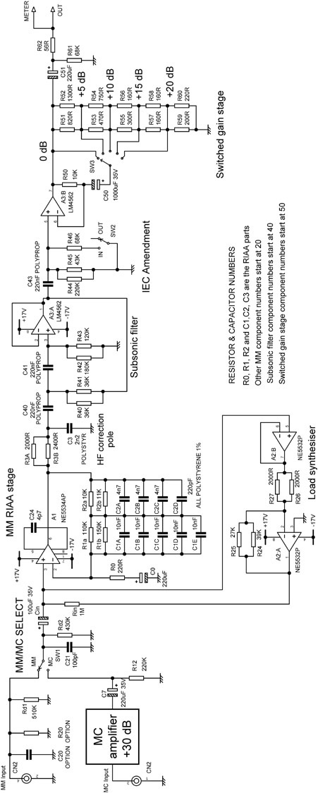
The MM RIAA stage is in Configuration-A with a gain of +30 dB (1 kHz) using 5 × 10 nF polystyrene capacitors to obtain the required value and improve RIAA accuracy. Multiple RIAA resistors R1, R2, and R3 are used to improve accuracy in the same way, using the 2xE24 format. The value of C0 is large at 220 uF, as the IEC amendment is not implemented in this stage, and tweaking the IEC amendment to compensate for its less-than-infinite value (see Chapter 7) was not considered necessary. The +30 dB (1 kHz) gain of the MM stage requires that an HF correction pole is required for accurate RIAA characteristic; this is implemented by R3A, R3B, and C3, which is polystyrene to avoid capacitor distortion.
A 5534A is used here for IC3, as it is quieter than half a 5532 and considerably quieter than an LM4562, with its higher current noise.
A load-synthesis circuit IC4 is used to make an electronic version of the required 47 kΩ loading resistor from the 1M resistor R16. The Johnson noise of the resistor is however not emulated, and so noise due to the rising impedance of the MM cartridge inductance is much reduced. R16 is made to appear as 47 kΩ by driving its bottom end in anti-phase to the signal at the top. IC4B prevents loading on the MM input, while IC4A is the inverting stage. Paired resistors R19, R20 and R17, R18 are used to improve the gain accuracy of the inverting stage and therefore the accuracy of the synthesised impedance. There is much more on the load-synthesis technique in Chapter 9.
The subsonic filter is a two-stage 3rd-order Butterworth highpass filter that is −3 dB at 20 Hz, with 2xE24 paired resistors again used to improve accuracy. It is a two-stage filter in that it consists of an under-damped 2nd-order highpass stage (C40, C41, R40–R43 etc.) combined with a 1st-order stage (C43, R44, R45) to give the maximally flat Butterworth response. My previous preamp designs have used a single-stage 3rd-order Butterworth, but I have found the two-stage configuration is preferred when seeking the best possible distortion performance.[3] An LM4562 is used in the filter as it significantly reduces distortion. The low impedance of the 220 nF capacitors means its higher current noise makes a negligible contribution to the overall noise performance.
The IEC Amendment can be switched in by placing an extra resistance R46 across the subsonic filter resistances R44, R45. This is something of an approximation but saves an opamp stage and is accurate to ± 0.1 dB down to 29 Hz. Below this the subsonic filter roll-off begins, and the IEC Amendment accuracy is irrelevant.
The switched-gain stage comes last in the signal path. It allows every MC and MM cartridge currently on the market, including the very low output MC models made by Audio Note, to receive the amount of gain required for optimal noise and headroom. The switched-gain stage is fully described in Chapter 5; gain is varied in 5 dB steps by a switch SW3 which selects the desired tap on the negative-feedback divider R51–R60. Each divider step is made in 2xE24 format to get the exact dB and improve effective tolerances. R35 provides continuity of DC feedback when the switch is altered.
Setting the correct gain can be done by reference to cartridge sensitivities and so on, but it is far more convenient to have some sort of level indication for guidance, hence the meter output shown in Figure 17.2. The Log-Law Level LED (LLLL) is my attempt to get as much useful information as possible from a single LED; it is, to the best of my knowledge, a new idea, and is fully described in Chapter 15 on metering.
Project 6: A High-Spec MM Amplifier Upgraded
Project 5 is a recent design and is not susceptible to much improvement (at present). The only obvious step is to convert the Configuration-A RIAA network to Configuration-C to reduce parts cost and PCB area occupied. The network required is exactly the same as in Project 4.
References
1. Signal Transfer Company SignalTransfer MM/MC phono amplifier www.signaltransfer.freeuk.com/RIAAbal.htm Accessed Nov 2016.
2. Self, D. “Elektor Preamplifier 2012” Elektor, Apr, May, June 2012.
3. Billam, P. “Harmonic Distortion in a Class of Linear Active Filter Networks” Journal of the Audio Engineering Society, Volume 26, No. 6, June 1978, p. 426.