Introducing the Microcontroller
A microcontroller is a type of microprocessor furnished in a single integrated circuit and needing a minimum of support components. Its name is sometimes abbreviated µC or MCU. It is in fact a small computer that contains a processing element, memory, and peripherals for input and output operations. The principal feature of microcontrollers are self-sufficiency and low cost. It is not intended to be used as a computing device in the conventional sense; that is, a microcontroller is not designed to be a data processing machine, but rather an intelligent core for a specialized dedicated system.
Microcontrollers are embedded in many control, monitoring, and processing systems. All the basic circuits discussed in this book contain at least one microcontroller. A few microcontrollers are designed as general-purpose devices, especially the type called digital signal processors (DSPs). However, most microcontrollers are used in specialized and embedded systems such as washing machines, telephones, microwave ovens, automobiles, and weapons of many kinds. In addition to a processor, memory, and input/output facilities, a microcontroller usually includes an internal clock and one or more peripherals such as timers, counters, analog-to-digital converters, serial communication facilities, and Watchdog circuits. Figure 6-1 shows a PIC 18F8720 microcontroller in an 80-pin TQFP surface-mount package.
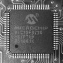
Figure 6-1 PIC 18F8720 Microcontroller on a Board. (Image from Wikimedia Commons)
More than two dozen companies in the United States and abroad manufacture and market microcontrollers. They range from 8- to 32-bit devices. Those at the low end are intended for very simple circuits and provide limited functions and program space, while those at the high end have many of the features normally associated with microprocessors. The most popular ones include several from Intel (such as the 8051), from Zilog (derivatives of their famous Z-80 microprocessor), from Motorola (such as the 68HC05), from Atmel (the AVR), the Parallax (the BASIC Stamp), and many from Microchip. In this book we focus on microcontrollers from Microchip, popularly called PICs.
Due to their low cost and easy availability, some microcontrollers have become very popular among amateur system designers. Large hobby communities have developed around the most popular ICs with many dedicated websites with thousands of examples of circuits and programs currently online. Their popularity, support, and availability of technology samples have been factors that determined our adoption of the PIC microcontrollers for this book.
PIC is a family of microcontrollers made by Microchip Technology. The original one was the PIC1650 developed by General Instruments. This device was called PIC for “Programmable Intelligent Computer” although it is now associated with “Programmable Interface Controller.” Microchip does not use PIC as an acronym; instead, they prefer the brand name PICmicro. Popular wisdom relates that PIC is a registered brand in Germany and Microchip is unable to use it internationally. The original PIC was built to be used with General Instruments’s CP1600 processor, which had poor I/O performance. The PIC was designed to take over the I/O tasks from the CPU, thus improving performance. In 1985, the PIC was upgraded with EPROM to produce a programmable controller. Today a huge variety of PICs are available with many different on-board peripherals and program memories ranging from a few hundred words to 32K.
The PIC primitive instruction set varies in length from about 35 instructions for the low-end devices to more than 70 for the high-end devices. The accumulator, which is known as the work register in Microchip documentation, is part of many in-structions because the PIC contains no other internal registers accessible to the programmer. The PICs are programmable in their native Assembly language, which is straightforward and not difficult to learn. C language and BASIC compilers have been developed and are available from several sources. Open-source Pascal, JAL, and Forth compilers are also available. Storing a program in a PIC microcontroller is popularly referred to as “blowing” a PIC.
One of the reasons for the commercial success of the PIC is the support provided by Microchip. This includes a professional-quality development environment called MPLAB which can be downloaded free from the company’s website. The MPLAB package includes an assembler, a linker, a debugger, and a simulator. Microchip also sells a low-cost in-circuit debugger called MPLAB ICD 2. Other development products intended for the professional market are also available from Microchip. The Microchip website furnishes hundreds, if not thousands, of free support documents, including data sheets, application notes, and sample code.
In addition to the documents and products on the Microchip website, the PIC microcontrollers have gained the support of many hobbyists, enthusiasts, and entrepreneurs who develop code and support products and publish their results on the Internet. This community of PIC users is an invaluable source of information and know-how easily accessible to the beginner and useful even to the professional. One such Internet resource is an open-source collection of PIC tools named GPUTILS, which is distributed under the GNU General Public License. GPUTILS includes an assembler and a linker. The software works on Linux, Mac OS, OS/2, and Windows. Another product named GPSIM is an open-source simulator featuring PIC hardware modules.
Programming a PIC microcontroller requires the following tools and components:
1. An Assembler or high-level language compiler. The software package usually includes debugger, simulator, and other support programs.
2. A computer (usually a PC) in which to run the development software.
3. A hardware device called a programmer that connects to the computer through the serial, parallel, or USB line. The PIC is inserted in the programmer and “blown” by downloading the executable code generated by the development system. The hardware programmer usually includes the support software.
4. A cable or connector for wiring the programmer to the computer.
5. A PIC microcontroller.
6. PIC programmers.
The development system (assembler or compiler) and the programmer driver are the software components. The computer, programmer, and connectors are the hardware elements. Figure 6-2 shows a commercial programmer that connects to the USB port of a PC. The one in the illustration is made by MicroPro.
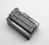
Figure 6-2 USB PIC Programmer by MicroPro.
Many other programmers are available on the market. Microchip offers several high-end devices with in-circuit serial programming (ICSP) and low-voltage programming (LVP) capabilities. These devices allow the PIC to be programmed in the target circuit. Some PICs can write to their own program memory. This makes possible the use of so-called bootloaders, which are small resident programs that allow loading user software over the RS-232 or USB lines. Programmer/debugger combinations are also offered by Microchip and other vendors.
A development board is a demonstration circuit that usually contains an array of connected and connectable components. Their main purpose is as a learning and experiment tool. Like programmers, PIC development boards come in a wide range of prices and levels of complexity. Most boards target a specific PIC microcontroller or a PIC family of related devices. Lacking a development board, the other option is to build the circuits oneself, a time-consuming but valuable experience. Figure 6-3 shows the LAB-X1 development board for the 16F87x PIC family.

Figure 6-3 LAB-X1 Development Board.
The LAB-X1 boards, as well as several other models, are products of microEngineering Labs, Inc. Some of the sample programs developed for this book were tested on a LAB-X1 board. Development boards from Microchip and other vendors are also available.
6.2.2 Prototyping a PIC Circuit
It is a risky proposition to write a PIC program and assume that it works correctly without testing. Testing a program is not difficult with a development board but only if the board is compatible with the microcontroller, and if it provides the hardware that we need to test. But often one of these elements is missing, which means that we must build the circuit for which the program was designed. Prototyping options and techniques, including breadboards, perfboards, and commercial PCBs, were discussed in Chapter 5.
PIC microcontrollers are classified by Microchip into three groups: baseline, mid-range, and high-performance. Within each of the groups, the PIC is reclassified based on the first two digits of the PIC’s family type. However, this sub-classification is not very strict because there is some overlap. For this reason we find PICs with 16X designations that belong to the baseline family and others that belong to the mid-range group. In the following sections we describe the basic characteristics of the various sub-groups of the three major PIC families with 8-bit architectures.
This group includes members of the PIC10, PIC12, and PIC16 families. The devices in the baseline group have 12-bit program words and are supplied in 6- to 28-pin packages. The microcontrollers in the baseline group are described as being suitable for battery-operated applications because they have low power requirements. The typical member of the baseline group has a low pin count, flash program memory, and low power requirements. The following types are in the baseline group.
The PIC10 devices are low-cost, 8-bit, flash-based CMOS microcontrollers. They use 33 single-word, single-cycle instructions (except for program branches, which take two cycles.) The instructions are 12-bits wide. The PIC10 devices feature power-on and device reset, an internal oscillator mode that saves having to use ports for an external oscillator. They have a power-saving SLEEP mode, A Watchdog timer, and optional code protection.
The recommended applications of the PIC10 family range from personal care appliances and security systems to low-power remote transmitters and receivers. The PICs of this family have a small footprint and are manufactured in formats suitable for both through-hole and surface-mount technologies. Table 6.1 lists the features of some members of the PIC10 family.

Two other PICs of this series are the 10F220 and the 10F222. These versions include four I/O pins and two analog-to-digital converter channels. Program memory is 256 words on the 10F220 and 512 in the 10F222. Data memory is 16 bytes on the F220 and 23 bytes in the F222.
The PIC 12C5XX family are 8-bit, fully static, EEPROM/EPROM/ROM-based CMOS microcontrollers. The devices use RISC architecture and have 33 single-word, single-cycle instructions (except for program branches which take two cycles). Like the PIC10 family, the PIC12C5XX chips have power-on reset, device reset, and an internal timer. Four oscillator options can be selected, including a port-saving internal oscillator and a low-power oscillator. These devices can also operate in SLEEP mode and have Watchdog timer and code protection features.
The PIC12C5XX devices are recommended for applications ranging from personal care appliances, security systems, and low-power remote transmitters and receivers. The internal EEPROM memory makes possible the storage of user-defined codes and passwords as well as appliance setting and receiver frequencies. The various packages allow through-hole or surface-mounting technologies. Table 6.2 lists the characteristics of some selected members of this PIC family.
Table 6.2
PIC 12Cxxx and 12CExxx Devices
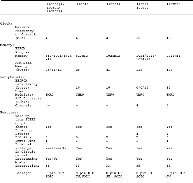
Two other members of the PIC12 family are the 12F510 and the 16F506. In most respects these devices are similar to the other members of the PIC12 family previously described. The one difference is that the 12F510 and 16F506 both have flash program memory. Table 6.3 lists the most important features of these two PICs.
Two other members of the PIC12F are the 12F629 and 12F675. The difference between these two devices is that the 12F675 has a 10-bit analog-to-digital converter while the 629 does not. Table 6.4 lists some important features of both PICs.
Several members of the PIC12 family (12F635, 12F636, 12F639, and 12F683) are equipped with special power-management features (called nano-watt technology). These devices are specially designed for systems that require extended battery life.
|
|
|
|
|
|
|
|
|
|
|
|
|
|
|
|
|
|
|
|
|
|
|
|
|
|
|
|
|
|
|
|
|
|
|
|
|
|
|
|
|
|
|
|
|
|
|
|
|
|
|
|
|
|
|
|
|
|
|
|
|
|
|
|
|
|
|
|
|
|
|
|
|
|
|
|
|
|
|
|
|
|
|
|
|
|
|
|
|
|
|
|
|
|
|
|
|
|
|
|
|
|
|
|
|
The single member of this family is the PIC14000. The 14000 is built with CMOS technology, which makes it fully static and gives the PIC an industrial temperature range. The 14000 is recommended for battery chargers, power supply controllers, power management system controllers, HVAC controllers, and for sensing and data acquisition applications. Table 6.5 lists the most important characteristics of this PIC.
|
|
|
|
|
|
|
|
|
|
|
|
|
|
|
|
|
|
|
|
|
|
|
|
|
|
|
|
|
|
|
|
|
|
|
|
|
|
|
|
|
|
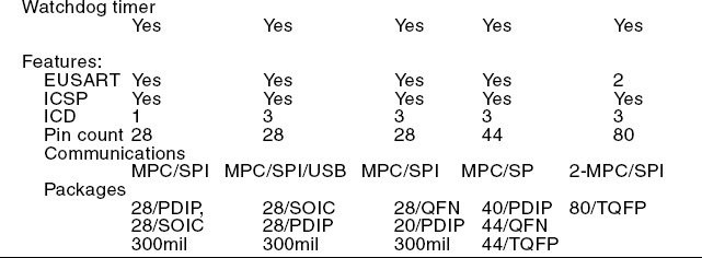
The mid-range PICs include members of the PIC12 and PIC16 groups. According to Microchip, all mid-range PICs have 14-bit program words with either flash or OTP program memory. Those with flash program memory also have EEPROM data memory and support interrupts. Some members of the mid-range group have USB, I2C, LCD, USART, and A/D converters. Implementations range from 8 to 64 pins. In the following sub-sections we list the basic characteristics of some mid-range PICs.
This is by far the most extensive PIC family. Currently, over 80 versions of the PIC16 are listed in production by Microchip. We selected a few of the most prominent members of the PIC16 family to list their most important features. The Microchip website has detailed information on any of these devices. Table 6.6 lists the features of some members of the PIC16 group.
6.3.3 High-Performance PIC Family
The high-performance PICs belong to the PIC18 group. They have 16-bit program words, flash program memory, a linear memory space of up to 2 Mbytes, as well as protocol-based communications facilities. They all support internal and external interrupts and a much larger instruction set than members of the baseline and mid-range families.

The PIC18 family has over 70 different variations currently in production. The PIC18 family uses 16-bit program words and are furnished in 18 to 80 pin packages. Microchip describes the PICs in this family as high-performance with integrated A/D converters. They have 32-level stacks and support interrupts. The instruction set is much larger and starts at 79 instructions. The PICs in this family have flash program memory, a linear memory space of up to 2 Mbytes, 8-by-8 bit hardware multiplier, and communications peripherals and protocols. Table 6-7 lists some members of the PIC18 family.