Constant-Voltage Bipolar Motor Controls
In Chapter 15 we discussed the hardware characteristics of bipolar and unipolar motors. From the circuit designer’s viewpoint, the fundamental difference between these motor types relates to the fact that bipolar motors contain a single winding per phase. Because there is a single winding, the current flow must be reversed in order for the rotor to turn. Another consequence of the bipolar motor structure is that the entire winding is activated during each cycle, while only half the winding is active in the unipolar design. Consequently, a bipolar motor generates more torque than a unipolar motor of the same size.
The bipolar design also has some drawbacks. One of them is that, in order to reverse current flow in the windings, bipolar motors require more complex control circuitry. The H bridge (discussed in Chapter 16) is a common circuit component that is used for this purpose. There is little difference in cost between unipolar and bipolar motors of the same weight. However, this difference is more significant if the increased torque and efficiency of the bipolar design is taken into account. A final consideration in choosing between unipolar and bipolar motors is that a unipolar motor can be used as a bipolar motor by ignoring the center taps in the coils. In summary, the differences can be listed as follows:
• Bipolar motors require more complex drive circuitry than unipolar.
• Bipolar motors produce higher torque than unipolar motors of the same weight.
• There is not much difference in cost between unipolar or bipolar motors of the same weight.
• Standard unipolar motors can be used in bipolar circuits.
Bipolar motor circuits require changing current polarity during stepping operations and that this is usually accomplished with an H bridge of one type or another. We must now add that bipolar stepper motor performance is dependent on the drive circuit to a high degree. Recall that higher speeds are achieved by reversing the stator poles more quickly, which also results in a gain in torque. However, increasing the reversal rate of the poles also increases inductance in the wiring. Here again, the higher inductance can be overcome by increasing voltage, but this requires limiting the current at these higher voltages.
These considerations have led to two different types of bipolar stepper motor circuits: one in which the voltage is held constant and another one in which the current is held constant. The constant-voltage type is sometimes known as the L/R design. Here L represents the winding inductance and R the resistance. Constant-current circuit types are referred to as chopper circuits. In chopper drives, the current in each winding is held approximately constant by varying the voltage. Initially, a high voltage is applied to each winding, which causes the current to rise quickly. When the current reaches a specified limit, the voltage is turned off, or chopped. The current now drops until it reaches another low limit, in which case the voltage is turned back on. Chopper drives require additional components in order to measure the winding current and to control switching, but the payoff is that stepper motors can be driven at higher speeds and torques than with constant-voltage circuits.
The control and translator stages in many circuits described in Chapter 17, in the context of unipolar motors, are compatible with the bipolar drivers described in this chapter. For example, the control and translator stage of circuit SMU-PIC16F84-1 can be coupled with several driver stages of bipolar circuits shown in this chapter. Also consider that in this chapter we only discuss bipolar circuits of the constant-voltage type. Chopper circuits are presented in Chapter 19, together with microstepping.
18.2 Simple, L293 Bipolar Circuit
In Chapter 16 we presented the L293 IC, which is a two H-bridge, four-channel driver that includes snubber diodes. The L293 can drive 1.2 A per channel; it is suitable for driving NEMA teen-size stepper motors. The L293, and equivalent ICs, are little more than a double H-bridge and they require a separate translator to provide the motor coil sequence via four input lines. Two enable lines are held high by wiring to the positive power supply. These lines can also be wired to the translator and used to turn the motor on and off. The four output lines from the L293 are wired to the motor coils. Four ground lines are located on the center of the IC. This design facilitates a large ground on the PCB, which serves as a heat sink
Figure 18-1 is a simple bipolar circuit that uses a microcontroller translator and an L293D driver IC. The SMB-L293D-1 circuit is the bipoiar version of the circuit SMU-PIC16F84-1 presented in Chapter 17 (see Figure 17-3).
The circuit in Figure 18-1 uses a microcontroller-based translator. Input is provided by means of four pushbutton switches, and motor speed, direction, and sequence mode are determined in software. Alternatively, the circuit can be easily modified to read other input devices, such as toggle switches or potentiometers. These inputs can then be used to control motor operation.
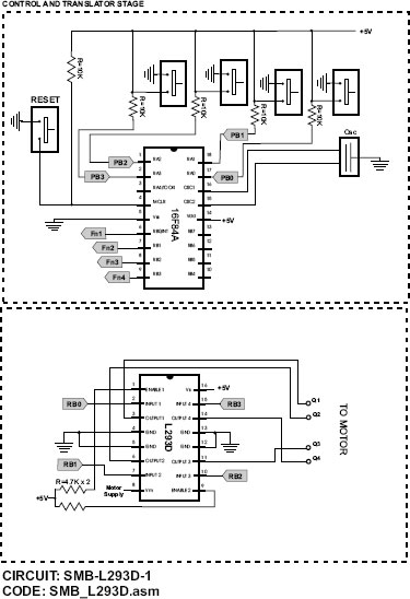
Figure 18-1 L293D-Based Bipolar Motor Driver.
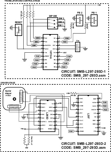
Figure 18-2 Bipolar Motor Driver with L297 and L293 ICs.
18.2.1 L297- and L293-Based Circuit
For circuits in which the microprocessor is overloaded, or to implement additional or finer motor controls, it is possible to insert an L297 motor driver IC between the translator and the H-bridge. The L297 hardware is described in Chapter 16. Although this chip is sometimes employed in simple circuits, such as the one presently described, it is most useful when the circuit takes advantage of all the chip’s capabilities. For example, the L297 can be configured in a “chopper” scheme, described previously. In Chapter 19 we develop a circuit that uses the L297 in this manner. The circuit designer should evaluate using the L297, or similar ICs, in constant-voltage circuits where most of the IC’s functionalities are unused. Figure 18-2 shows a simple circuit that uses the L293 and L297 ICs.
Note that many of the L297 pins are left floating in circuit SMB-L297-293D-2. These pins correspond to features and functionalities of the L297 that are not used in the circuit.
18.2.2 Minimal L297- and L298-Based Circuit
The major limitation of the L293 IC is its limitation of 1.2 A peak output current per channel. The L298, on the other hand, allows up to 3.5 A per channel, which triples the current-carrying capacity of the L293. A simple L297/L298 circuit is shown in Figure 18-3.
Circuit SMB-L297-298-1 shown in Figure 18-3 uses few of the features of both the L297 and the L298. The principal characteristic of this circuit is its higher capacity as the L298 allows an operating supply voltage of up to 46V and 4 A. The L298 IC includes capabilities not used in this circuit, such as sensing the output voltage. This feature can be used in input voltage chopping, which is implemented in circuits developed in Chapter 19. Because chopping is not supported by circuit SMB-L297-298-1, the SENSE A and SENSE B lines of the L298 are wired to ground. The L298 is also used in driving relays, solenoids, and DC motors.
Additional toggle switches in the control and translator stage could be used to control other modes or stages. In circuit SMB-1297-298-1, one toggle switch controls direction, another one selects between full- and half-step modes, a third one is wired to the L297 ENABLE line and allows turning the motor on and off. An additional toggle switch could be added to the circuit to provide selecting between high and low speeds. Because there are several unused ports in the translator, it is easy to add more input sources in order to control other features of the L297. Also note that the ENABLE, RESET, and both INH lines of the L297 are active low. In the circuit these lines are disabled either by holding them high or by leaving them floating. Similarly unused lines in the L298 are either grounded or held high with 4.7K pull-ups. Most of these lines are put to good use in the more powerful circuits developed in Chapter 19.
The programs listed in the following section demonstrate the programming discussed in this chapter.
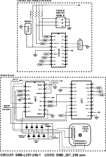
Figure 18-3 Bipolar Motor Circuit with L297 and L298 Drivers.
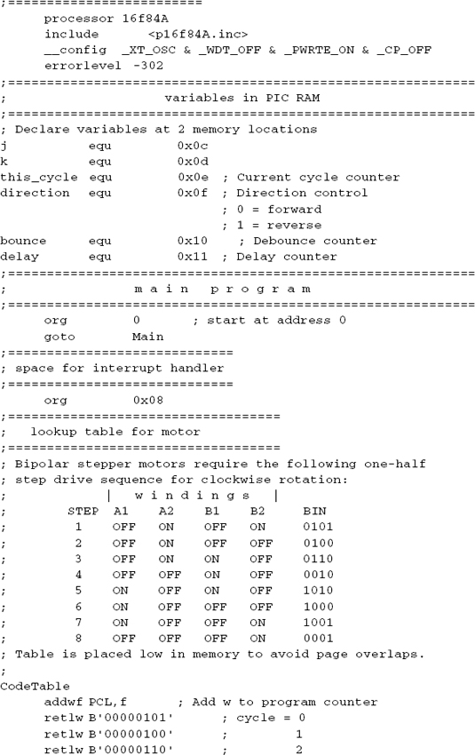
The program SMB_L293D.asm, listed below and in this book’s software resource, drives a bipolar stepper motor in a one-half step mode. The program uses a lookup table for the sequence codes. Two pushbutton switches, wired to ports A3 and A2, activate slow rotation in the forward or reverse direction. Two other pushbuttons, wired to ports A0 and A1, control slow and fast rotation. Code uses an access code table with a pointer, that is either incremented or decremented according to the selected direction. Fast and slow execution are determined by a local variable.


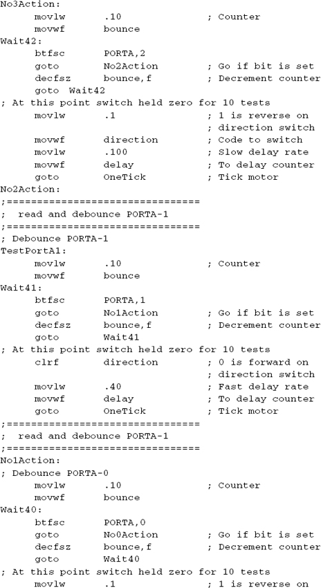

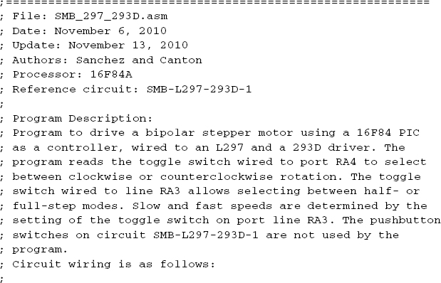
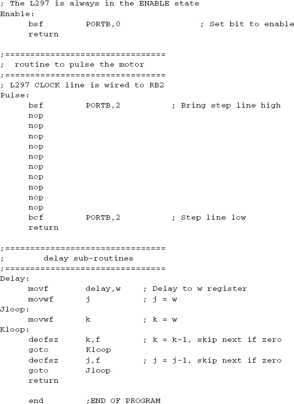
The sample program SMB_297_293D.asm, listed below and in this book’s software resource, drives a bipolar stepper motor using a 16F84 PIC as a translator, wired to an L297 and a 293D driver. The program reads the toggle switch wired to port RA4 to select between clockwise or counterclockwise rotation. A toggle switch wired to line RA3 allows selecting between half- or full-step modes. Slow and fast speeds are determined by the setting the toggle switch on port line RA3. The pushbutton switches on circuit SMB-L297-293D-1 are not used by the program.


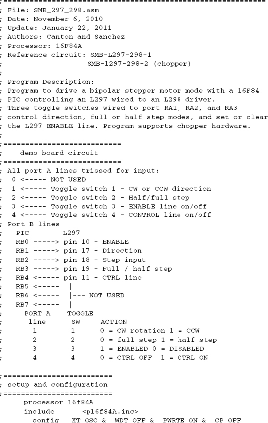
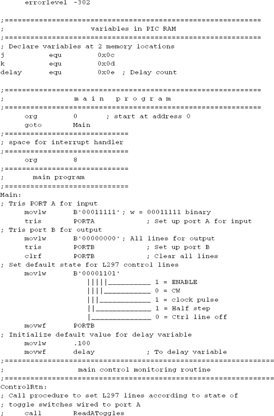
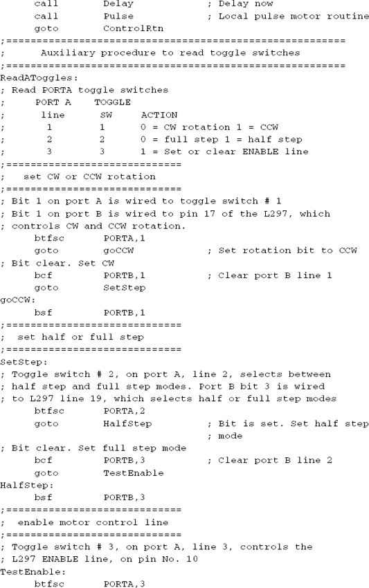
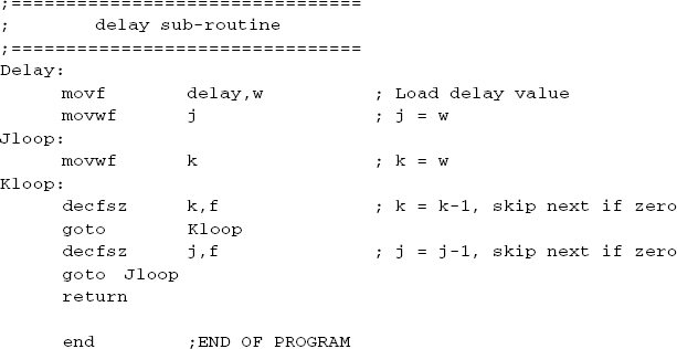
The program SMB_297_298.asm, listed below and in this book’s software package, is a simple, noninterrupt - driven control program for circuit SMB-L297-298-1 shown in Figure 18-3. The program uses a delay routine to time the motor pulses. The three toggle switches are read by code and the corresponding L297 control lines are set or reset accordingly. The program could be improved by making it interrupt driven.