
15.1 Description and Operation
A simple DC motor rotates when a voltage is applied to its terminals; therefore its control is quite simple. Stepper motors, on the other hand, convert electrical pulses into discrete units of rotational movement, which can be controlled independently and without a feedback mechanism. Typically, the shaft or rotor is toothed, while the stator contains several windings that are energized in a specific order. The electro-magnetic attraction of the windings force the alignment of the toothed rotor thus producing rotation. Figure 15-1 is a diagram of a stepper motor with eight windings and six teeth on the rotor.

Figure 15-1 Cross-Section of a Typical Stepper Motor.
The motor of Figure 15-1 belongs to a group called variable-reluctance motors. Permanent magnet and hybrid stepper motors are also common. We have chosen the VR type for the illustration due to its simplicity.
Step 1 in Figure 15-1 shows that windings labeled 1 and 5 are initially energized, forcing the alignment of rotor teeth A and D. In Step 2, stator windings 2 and 6 are energized, forcing rotor teeth C and F into alignment and rotating the rotor clockwise. Steps 3 and 4 complete the sequence. At the end of Step 4, the rotor would have turned 45 degrees, which means that the rotor moves 5.625 degrees per pulse of the stator winding pairs and that, in this case, one complete revolution of the rotor requires thirty-two individual pulses.
Rotation of a stepper motor requires that the electrical pulses applied to the stator windings follow a definite sequence. In the motor of Figure 15-1, the sequence for clockwise rotation consists of applying current to the windings labeled 1-5, 4-8, 3-7, and 2-6, in that order. If the pulses were applied in some other order, the rotation of the motor would be different or would completely fail. By the same token, by applying the pulses in some other order the motor can be made to rotate in a counterclockwise direction. The speed of rotation of a stepper motors is determined by the frequency of the pulses and the amount of rotation by the number of pulses. For example, the motor in Figure 15-1 could be made to rotate 180 degrees (one-half revolution) by applying sixteen pulses only. These controls make stepper motors powerful devices for use in embedded systems and robotics.
The following are the fundamental characteristics of stepper motors in general:
• The motor has full torque at stand-still condition if the windings are energized.
• The rotation angle of the motor is determined by its design and by the number and sequence of the applied pulses.
• Positioning error of a stepper motor is in the range of 3 to 5 percent. This error does not accumulate from step to step.
• Stepper motors have long lives because they have no contact brushes to wear out.
• The position of a stepper motor can be determined from the number of input pulses applied. This feature, called open-loop operation, means that motor control is simple and straightforward because no feedback signals or optical senders are required.
• Stepper motors have good response at start time and can be rapidly stopped or reversed.
• Because stepper motors do not have brushes, they do not produce electrical arcs, which are undesirable or even dangerous.
Stepper motors are a good choice in applications that require control over motor speed, angle of rotation, direction of rotation, position, or synchronization. They find frequent use in robotics, office equipment such as printers and fax machines, in floppy and hard disk drives, in medical equipment, in computer control of machine tools (CNC), and in automobiles.
aAlthough there are several possible classifications of stepper motors, the hardware design falls into one of three main types:
This type, which has been around the longest time, consists of a soft core, which is often toothed, and a stator containing several electromagnets. The term variable reluctance refers to the principle that maximum attraction occurs between poles with minimum gaps. In Figure 15-1, which depicts a variable reluctance motor, you can see that in each consecutive step the stator windings closest to the rotor poles, in a clockwise direction, are energized in sequence.
These are often referred to as tin can motors. This type, which is the cheapest to build and most common one, consists of a permanent magnet rotor without teeth. Figure 15-2 shows is a schematic drawing of a permanent magnet type stepper motor.
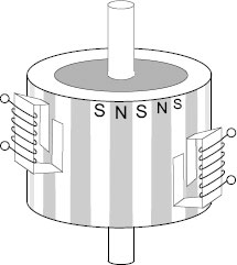
Figure 15-2 Schematic of a Permanent Magnet Stepper Motor.
In the motor of Figure 15-2, the magnetic fields in the rotor are in line with the motor shaft and the rotor does not have teeth. The rotor magnetic fields alternate north and south. As the windings in the stator are energized, the poles in the rotor are attracted to the opposite poles in the stator and the motor rotates.
Hybrid stepper motors use a combination of the variable reluctance and permanent magnet schemes. The rotor in the hybrid motor is both toothed and magnetized. The teeth provide a path for the magnetic flux, which increases the holding power and the magnetic characteristics of the motor. Because of their more complex construction, hybrid motors are considerably more expensive than permanent magnet types. At the same time, they have better resolution, and higher torque and speed.
15.1.2 Unipolar Stepper Motors
In electronics, a pole (normally labeled North or South) is a region where magnetic flux density is concentrated. Both the rotor and the stator of stepper motors have poles. Similar poles repel each other (NN or SS) and opposite poles attract (NS or SN). Thus, magnetic attraction of unlike poles will make the rotor move until its north poles are located opposite the stator south poles, and vice versa.
Although stepper motors can be cataloged in several ways, from a programming and control viewpoint the most useful classification is by the number of poles. Unipolar stepper motors have two windings per phase, one for the direction of each magnetic field. The magnetic poles can be reversed by selecting which winding is energized. By not having to change the direction of the magnetic field, the circuit of a unipolar stepper motor is very simple. Figure 15-3 depicts a unipolar stepper motor.
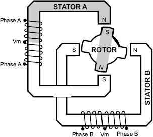
Figure 15-3 Unipolar Stepper Motor Schematics.
Note that the unipolar motor in Figure 15-3 has two windings per phase, one for each direction of the magnetic field. The center tap (labeled Vm) is connected to a common line. This arrangement allows changing the magnetic pole of the winding without reversing the direction of the current flow. The two-phase common line is sometimes joint internally, in which case the motor will have five wires. If the common lines are separate for each winding, then the motor will have six wires. In the illustration, the top half of phase A is shown activated (light gray color). The lower half (labeled phase bar A) is energized separately. Similarly, the center tap creates two separate phases in stator B, labeled phase B and phase bar B. The presence of two phases in each winding explains why unipolar motors are sometimes referred to as four-phase motors, while in reality they have only two phases.
15.1.3 Determining Unipolar and Bipolar Wiring
It is possible to determine the wiring of a unipolar or bipolar stepper motor with either four, five, or six leads. The only instrument needed for this test is an ohmmeter.
A four-wire motor is always a bipolar motor. The two windings can be easily identified with an ohmmeter: two wires that show finite resistance (closed circuit) are the ends of a winding.
STEP 1: Find the wires belonging to each of the two windings by measuring resistance between wires. There will be two groups of three wires that show finite resistance. Label these groups of three wires as group A and group B.
STEP 2: Two wires in group A will show higher resistance than any other combination. These are the end leads of the windings and should be labeled A and B. The third wire in the group is the common tap and should be labeled VmA. The common lead will show one-half of the resistance when tested against wires A or B.
STEP 3: Similarly, two wires in group B will show higher resistance than any other combination. These are the end leads of the windings and should be labeled C and D. The third wire in the group is the common tap and should be labeled VmB.
STEP 4: Wires A and B should show infinite resistance when tested against wires C, D, or VmB. By the same token, wires C and D should show infinite resistance (open circuit) when tested against wires A, B, or VmA.
STEP 1: Find a single wire that shows finite resistance with all the other four wires in the motor. This is the common lead and should be labeled Vm.
STEP 2: Find two other wires, excluding Vm, that show finite resistance with each other and label them A and B, respectively.
STEP 3: Similarly, the two remaining wires will show finite resistance when tested with each other. They should be labeled C and D.
STEP 4: Wires C and D should show infinite resistance (open circuit) when tested against wires A or B. Wires A, B, C, and D should show finite resistance (closed circuit) when tested against Vm.
Figure 15-4 shows the wiring diagram for six- and five-wire unipolar motors.
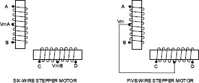
Figure 15-4 Six- and Five-Wire Stepper Motors.
Some unipolar stepper motors are designed to have two individual windings for each stator phase. These motors, sometimes called bifilar motors, have two common leads in each winding and the motor has a total of eight wires. The advantage of this design is that these motors can be operated as unipolar or bipolar devices.
Bipolar motors have a single winding per phase. The motor operates by reversing the current flow in the winding, thus reversing the magnetic poles. Because there is a single winding for each phase, there is no center tap and the motor has four wires. Figure 15-5 shows the schematic of a bipolar stepper motor.
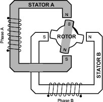
Figure 15-5 Schematic of a Bipolar Stepper Motor.
The entire winding of a bipolar motor is activated in each cycle, while only half the winding is activated in a unipolar motor. This results in bipolar motors producing more torque than unipolar motors of the same size. On the other hand, because the current flow in the winding must be reversed, bipolar motors require more complex control circuitry. The most common circuit used in reversing the polarity of bipolar motors is known as an H bridge. One H bridge is required for each winding in a bipolar motor. The H bridge is discussed later in this chapter.
Stepper motors can be controlled by means of general electronic circuitry, by ICs specially designed for this purpose, or by signals from microprocessors or microcontrollers. Very often, a stepper motor circuit combines all three types of components. The complexity of the control circuitry of a stepper motor depends on the type of motor and on the degree of control required by the application. Unipolar motors, although less efficient, are easier to control than bipolar ones. Also, an application that is limited to turning on and off a stepper motor, at a fixed speed and rotation direction, would be simpler to design and build than one that must vary the speed, change the direction, and select among several modes of operation. Figure 15-6 is a photograph of a breadboard circuit for controlling a stepper motor.

Figure 15-6 Breadboard Circuit for a Unipolar Motor.
The circuit in Figure 15-6 uses a 16F84A PIC microcontroller to handle the signals to the unipolar stepper motor. The 4050 IC is a noninverting hex buffer that serves to drive the higher current loads of the TIP 120 Darlington transistors. The four diodes are an additional safety to protect the circuit from backflows. The two white pushbuttons, when held down, activate slow rotation in the forward and reverse directions, respectively. The dark gray pushbuttons do the same in fast rotation. The circuit and software are developed and explained later in this chapter.
The sequence in which the windings or winding sections are activated in a unipolar or bipolar stepper motor is called the stepping mode. Three stepping modes are most common, although a fourth mode, called microstepping, is occasionally used. The general characteristics are as follows.
In this mode a single winding is energized at a time. The wave mode is easy to implement in the control hardware but provides significantly less than the rated torque of the motor. If the four windings of unipolar motors are labeled A, B, C, and D, then in the wave drive mode the windings are energized in the sequence: A → B → C → D. Figure 15-7 shows a unipolar motor in the first cycle of a wave mode sequence.

Figure 15-7 Unipolar Motor in Wave Mode Activation Sequence.
The straight arrows in Figure 15-7 show the various positions of the rotor as the windings are activated in sequence. The solid arrow represents the original position of the rotor and the dashed arrows the subsequent positions as windings B, C, and D are turned on. The activation sequence in Figure 15-7 results in a clockwise rotation. If the windings were activated in the order A → D → C → B then the motor would rotate counterclockwise. Note that in the wave mode, only 25 percent of the motor’s total windings are energized at any time.
In the full step mode two windings are activated during each sequence step. Because the rotor is equally attracted to the two active windings, it takes an intermediate position. If the four windings of a unipolar motor are labeled A, B, C, and D, then in the full step drive mode the windings are energized in the sequence: AB → BC → CD → DA. Figure 15-8 shows a unipolar motor in the first cycle of a full step mode sequence.
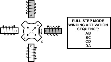
Figure 15-8 Unipolar Motor in Full Step Mode Activation Sequence.
As in Figure 15-7, the straight arrows show the various positions of the rotor as the windings are activated in sequence. The activation sequence in Figure 15-8 results in a clockwise rotation. If the windings were activated in the order AD → DC → CB → BA then the motor would rotate counterclockwise. In full step mode, 50 percent of the motor’s total windings are energized at a time, resulting in higher efficiency than in the wave mode.
The half step mode combines the winding excitation sequence of the wave mode and the full step mode in order to double the number of steps in each full revolution of the rotor. This means that single winding and double winding excitation are generated alternatively, as shown in Figure 15-9.
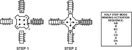
Figure 15-9 Unipolar Motor in Half-Step Mode Activation Sequence.
Here again the straight arrows show the various positions of the rotor as the windings are activated in sequence. In the half-step mode, the motor rotates one-half the angle during each activation cycle of the windings. The activation sequence in Figure 15-9 results in a clockwise rotation. By reversing the order of the cycles, the motor is made to rotate counterclockwise.
Operating a stepper motor in any of the three modes discussed in this section results in a jerkiness that varies according to the number of steps. This jerkiness is a direct result of the abrupt changes in current magnitude or direction, which apply torque to the rotor abruptly, as shown by the square wave current changes in Figure 15-10.
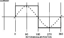
Figure 15-10 Current Transitions in Stepping.
With the waveform shown in Figure 15-10, as the voltage rises abruptly, so does the attraction of the stator windings on the motor poles. As the voltage declines abruptly at the end of each step, the attraction is instantly turned off. This results in the less-than-smooth movement sometimes associated with stepper motors. The square wave in Figure 15-10 approximately represents the level of attraction of the windings on the rotor at various positions in the step cycle.
Microstepping reduces or eliminates this effect by varying the current in the windings so as to produce a uniform attraction on the rotor throughout the step cycle. This can be achieved by modifying the current applied to the windings so as to follow the sine waveform shown by the dotted line in the illustration. In this case, the attraction on the rotor is uniform throughout the step cycle and the motor rotates smoothly. Because microstepping requires control over the current levels, it results in more complex circuitry, more sophisticated hardware, and more complex programming. Microstepping is covered in detail in Chapter 19.